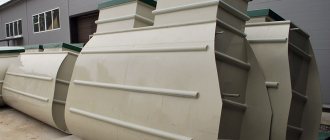
At dachas and country houses that are not connected to a centralized sewerage system, various models of septic tanks are used for the collection and primary treatment of liquid household waste. Effluents subjected to mechanical and biological purification contain a small percentage of contaminants at the exit from an autonomous treatment plant. To completely clean household waste, a filtration field for a septic tank is built. Its area depends on the volume of the treatment plant and the amount of sewage processed in the septic tank per day. The wastewater passes through the bulk filter material and is absorbed into the lower layers of the soil. If the requirements for the construction of such structures are observed, there is no harm to the ecology of the site. However, after a certain period of time it is necessary to replace the filter layer, while the contaminated soil is removed and new soil is filled in.
The operation of filtration fields is based on the soil’s ability to naturally purify itself. The operating principle of these treatment facilities is clearly presented in the video:
Filtration field as part of the sewer system
Without the main part that performs the initial processing of sewage waste, that is, a septic tank, the filtration field is not used, since its purpose is to further purify the already purified liquid. To make it clearer, let's look at how VOC works.
The cleaning process begins in the storage tank, where sewage is divided into different fractions: solid mineral waste falls out in the form of sediment, fat floats and forms a film, and some substances remain in the water as suspension. If air supply is not provided, the process of decomposition of some of the waste occurs due to the activity of anaerobic bacteria.
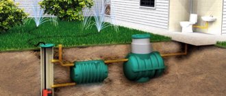
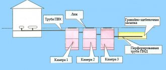
Scheme of a sewerage system consisting of an internal sewerage system, a two-chamber septic tank with an air supply (storage + aerobic compartment), a collector and a filtration field
Then the liquid flows into the next compartment, equipped with ventilation, where aerobic microorganisms process wastewater. They form activated sludge, which can later be used as fertilizer. The result of two-stage purification is a slightly cloudy liquid that is not yet suitable for use.
It turns into process water or simply ends up in the ground (ditch, pond) after undergoing post-treatment, which is carried out in the following way:
- on the filtration field;
- in the infiltrator;
- directly in the ground;
- in the filter well.
A typical multi-stage system, which has dozens of design options, is good because it effectively cleans sewage waste, reduces cooperation with sewer trucks to a minimum and keeps the ecology of the garden plot clean. Now let’s take a closer look at the design of the filtration field.
Exploitation
The service life of a septic tank filtration field will depend on the quality of the system installation, its reasonable use and the composition of the wastewater. It is believed that the filtration field functions effectively for 7 years.
If over time, during the operation of the filtration fields, you begin to notice that the water stagnates and is poorly absorbed into the soil, this means that silting of the filter layer has occurred. In this case, you will need to either disassemble the structure and replace the filter layer, or move the field to another location. It is impossible to avoid clogging of the cleaning fields. It is possible to delay this process by improving the quality of cleaning in the septic tank or by installing an additional layer of geotextile to prevent soil from entering the filtration layer.
PF design features
A filtration field is a relatively large area of land where secondary purification of liquid occurs.
This cleaning method is exclusively biological, natural in nature, and its value is in saving money (no need to buy additional devices or filters).
The size of the PF depends on the area of free territory and the landscape features of the garden plot. If there is not enough space, instead of the PF, an absorption well is installed, which also filters the liquid before it enters the ground
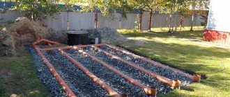
A typical filtration field design is a system of parallel laid drainage pipes (drains), which extend from the collector and are placed at regular intervals in ditches with a thick sand and gravel layer.
Previously, asbestos-cement pipes were used, but now there is a more reliable and economical option - plastic drains. A prerequisite is the presence of ventilation (vertically installed risers that provide oxygen access to the pipes).
The design of the system is aimed at ensuring that the liquid is evenly distributed over the designated area and has a maximum degree of purification, so there are several important points:
- distance between drains – 1.5 m;
- length of drainage pipes – no more than 20 m;
- pipe diameter – 0.11 m;
- intervals between ventilation risers – no more than 4 m;
- the height of the risers above ground level is at least 0.5 m.
To allow natural movement of liquid, the pipes have a slope of 2 cm/m. Each drain is surrounded by a filtering “cushion” of sand and pebbles (crushed stone, gravel), and is also protected from soil ingress by geofabric.
One of the complex variants of the device: after cleaning in the filtration field, the water enters a storage well, from where it is pumped out using a pump. Its further path is into a pond or ditch, as well as to the surface for irrigation and technical needs.
There is one condition, without which the installation of a septic tank with a filtration field is impractical. Special permeability properties of the soil are required, that is, on loose coarse and fine clastic soils that do not have connections between particles, it is possible to construct a post-treatment system, but dense clay soils, the particles of which are connected in a consolidated manner, are not suitable for this.
Types of infiltrators for septic tanks
There are many options for clarified water purification systems:
For sandy or peat soil, as well as variable groundwater level - a 400 mm plastic well, which will be used to drain wastewater,
With high and variable groundwater level, sand, peat or loam - a well made of concrete rings,
For low groundwater level and soil types such as sand and peat - buried drainage under the septic tank,
Under the same conditions, you can use gravity drainage into a 400 mm plastic well,
With low and variable groundwater level, sand, loam or peat - a well made of concrete rings for drainage by gravity.
Typical device diagram
Whatever the general dimensions of the filtration field, its design consists of the following parts:
- collector (control well, distribution well);
- networks of plastic drains (drainage pipes with holes);
- ventilation risers;
- filter pad.
Traditionally, the drainage layer is made of sand and gravel (crushed stone, pebbles). Geotextiles are used to protect drains. A sewer system with PF looks like this:
Pay attention to the thickness of the drainage pad. The minimum indicator is considered to be a total thickness of 1 m; in this diagram it is greater: crushed stone - 0.3-0.4 m, sand - 0.8-1 m
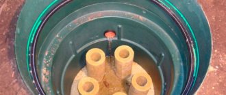
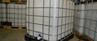
When building a filtration field with your own hands, it is not necessary to build the collector yourself - you can find plastic sewer containers of the required volume on sale.
They often do without a distribution well, connecting directly the septic tank and the pipe system - but this is convenient for small-sized PFs.
Diagram of the filtration field with an area of 4 m x 3.75 m. The distance between the drains is 1.5 m, each drain pipe is equipped with a ventilation riser. As an underground filter - a “cushion” of sand and crushed stone with a layer of geotextile
Sometimes, instead of PF, ready-made plastic devices - infiltrators - are used. They help out when there is a shortage of free space, and the soil does not have layers of loam and sandy loam and has sufficient permeability properties.
If desired, you can install several infiltrators connected by pipes in series.
Scheme of a local sewer system with an infiltrator. It is not recommended to plant flower beds in filtration fields, as the root system can damage the pipes. For an infiltrator, on the contrary, flower decor is the most acceptable option
Next, we’ll look at how to properly design and install a PF.
Primary requirements
- Drainage pipes with risers for ventilation must be laid on a filter layer of crushed stone.
- Do not make treatment facilities near residential buildings and water sources.
- The lower filter sand layer should be below the soil freezing level.
- The distance between drainage pipes and groundwater must be more than one meter.
It is important to know that the most effective drainage systems are those installed on sandy soils. In sandy soils, you can discharge 30 liters per day. per m of drainage system, in sandy loam soils - 15 l/day. and in loams - even less. To increase the efficiency of the drainage system, the pipes are lengthened and the thickness of the filter layer is increased.
Are there other solutions?
Not everyone can use the filtration field as a method of post-treatment of sewage waste. What should those who own a piece of clay land or have built a house in an area with a high groundwater level do?
Recommendations for choosing septic tanks for high groundwater levels are described in this article.
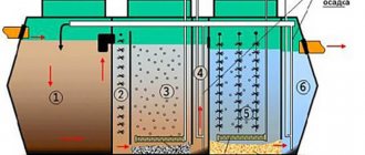
Scheme of operation of a biological treatment station. After passing through several tanks equipped with aerators, airlifts and filters, the water becomes 98% pure. The main function of waste processing, as in septic tanks, is performed by anaerobic and aerobic bacteria
It is also possible to create a sewer system with a filter well, but its installation also requires a number of conditions (for example, non-clayey soil and the location of groundwater a meter below the conditional bottom of the well).
If you simply install a septic tank without further treatment, insufficiently clarified and disinfected water will enter the soil and an unpleasant odor may appear.
Story
Plan of Lyubertsy irrigation fields in 1927
The fields were built in 1907-1912 as part of the second stage project. Wastewater was supplied to the fields from the Main Pumping Station through the Zagorodny Lyubertsy Canal.
Following the construction of modern sewage treatment plants in the 1960s, use of the fields gradually ceased.
Development
The area began to be developed in 2008, in parallel with the restoration of areas on the site of former aeration fields. As of 2011, it was planned to build housing with a total area of 4 million square meters and organize 18 thousand new jobs on an area of about 500 hectares. To determine the directions for urban development of the territory of the sludge sites of the Lyubertsy aeration station, an “Urban planning concept for the development of the territory of the sludge sites of the Lyubertsy aeration station, taking into account the adjacent territories of Moscow and the Moscow region” was developed.
Transfer to Moscow
In June 2011, an agreement on the border between Moscow and the Moscow region was signed, later approved by regional parliaments. According to this resolution, in particular, a site with an area of 578.9 (Lyubertsy Fields) was transferred to Moscow from the composition. The boundary change was approved. On September 28, 2011, it adopted changes to the laws of the city of Moscow, according to which the Lyubertsy aeration fields were annexed to the district.
What is it ↑
This is a special piece of land that performs biological treatment of wastewater passing through it. A specific place is equipped for filtration fields to increase the efficiency of waste treatment.
To organize them, drainage ditches and spray pipes are laid underground. For the system to function, crushed stone is laid at the bottom of the trenches, and a gravel-sand layer is placed underneath it. This creates a filter element that accepts household waste.
The wastewater leaving the dacha septic tank is moved by gravity or using a pump to the filter zone. Then they enter the distribution pipe, and from it the liquid is separated and discharged into the ground through spray products.
Photo: filtering process