ADDED 12/23/2017 12:24
If the circuit is a little complicated, you can take it from an old BURS. There is generally only one lamp, 6F5P it seems.
Source
Purpose and principle of operation of the ionization electrode
Ionization electrode for monitoring the presence and state of the flame. Automatic shutdown of gas supply when the burner flame goes out. Monitoring the state of the air-gas mixture and restoring the combustion process. Combination of ignition and control functions in one device.
Ionization electrodes are used in gas burner flame control sensors. Their main task is to signal to the control unit that combustion has stopped and the need to shut off the gas supply.
These devices are used to control flame continuity in industrial furnaces, home heating boilers, gas water heaters and kitchen stoves. They are often duplicated by photosensors and thermocouples, but in the simplest thermal apparatus, the ionization electrode is the only means of controlling the ignition of the gas and the continuity of its combustion.
Ionization method
The second most popular is the ionization method. In this case, the basis of the method is observation of the electrical properties of the flame. Flame control sensors in this case are called ionization sensors, and the principle of their operation is based on the fact that they record the electrical characteristics of the flame.
This method has a rather strong advantage, which is that the method has virtually no inertia. In other words, if the flame goes out, the process of fire ionization disappears instantly, which allows the automatic system to immediately stop supplying gas to the burners.
Purpose, operating principle and design of the ionization electrode
If for some reason the flame disappears in the heating device, the gas supply must be stopped immediately. Otherwise, it will quickly fill the volume of the installation and the room, which can lead to a volumetric explosion from an accidental spark.
Therefore, all heating installations operating on natural gas must be equipped with a system for monitoring the presence of flames and blocking the gas supply.
Ionization electrodes for flame control usually perform two functions: during ignition of gas from the igniter, they allow its supply in the presence of a stable spark, and when the flame disappears, they send a signal to turn off the gas of the main burner.
Principle of operation
The operating principle of the ionization electrode is based on the physical properties of the flame, which is essentially a low-temperature plasma, i.e., a medium saturated with free electrons and ions and therefore electrically conductive and sensitive to electromagnetic fields.
Typically, it is supplied with positive potential from a DC source, and the burner body and igniter are connected to the negative potential.
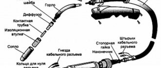
The figure below shows the process of current generation between the igniter body and the electrode rod, the raised end of which is designed to control the flame of the main burner.
The process of igniting gas in a heating installation occurs in two stages. At the first stage, a small amount of gas is supplied to the igniter and the electric spark ignition is turned on. When a stable ignition occurs in the igniter, ionization occurs and a direct current of hundredths of milliamps begins to flow.
The electrode control device sends a signal to the control system, the solenoid valve opens, and the main gas flow is ignited. From this moment, the electrode generates a control signal from the ionization of its flame.
The control system is set to a certain level of ionization, therefore, if its intensity decreases to a predetermined limit and the current in the plasma drops, the gas supply is turned off and the flame is extinguished. After this, the entire cycle using the igniter is repeated automatically until the combustion process becomes stable.
One of the main advantages of ionization electrodes is the instant response speed when the flame goes out. In contrast, thermocouple sensors generate a signal only after a few seconds, which they require to cool down.
In addition, ionization electrodes are inexpensive because they have a very simple design: a metal rod, an insulating sleeve and a connector. They are also very easy to operate and maintain, which consists of cleaning the rod from carbon deposits.
The disadvantages of ionization control sensors include their unreliability when working with gas fuel containing large proportions of hydrogen or carbon monoxide. In this case, an insufficient number of free ions and electrons is generated in the flame, which makes it impossible to maintain a stable current. In addition, this method may not be suitable when working in dusty conditions.
Design features
At the same time, the temperature in the upper part of the flame when burning natural gas can reach 1600 °C, so control electrodes are placed at its root, where the temperature is lower - from 800 to 900 °C.
The insulating base of the ionization electrode, with which it is mounted on the igniter, is a high-strength and heat-resistant ceramic sleeve.
The ionization electrode can only be a control electrode, or it can perform two functions at once: ignition and control. In the second case, to ignite the igniter flame, high voltage is applied to it, forming a spark.
After a few seconds it turns off, switches to DC power and enters control mode. If the electrode performs only a control function, then its insulation, connector and cable must meet the requirements of low-voltage equipment operated at high temperatures.
When using it as an igniter, the insulation resistance must withstand a breakdown voltage of 20 kV, and the connection to the control unit must be made with a high-voltage cable.
When installing an ionization electrode into the body of a specific burner, it is necessary to use a product of optimal length. A rod that is too large will overheat, become deformed, and become covered with carbon deposits faster.
In the case of a short length, situations are possible when the ionization flow is interrupted when the flame moves from the end of the electrode to the other edge of the burner body. In real conditions, the length of the electrode is usually selected experimentally.
In household gas stoves, electric spark ignition electrodes are used for ignition, and thermocouple sensors are used to control the flame. Why aren’t ionization electrodes used separately or combined in household devices?
After all, they are cheaper than thermocouples. If you know the answer to this question, please share the information in the comments to this article.
Source
In what cases is it necessary to adjust the burner flame?
An atmospheric gas burner for heating equipment often fails. It is equipped with models of both wall-mounted and floor-standing boilers. The injection burner of floor-standing equipment reduces its efficiency for various reasons:
- Burner power is too high. This happens when a high-power burner is purchased for small heating equipment. At the same time, there is not enough space for combustion, the air flow for such power is weak, which leads to the transition of the flame from blue to yellow, sooting of the combustion chamber and chimney.
- If the chimney is poorly cleaned, the boiler draft deteriorates. At the same time, waste combustion products are poorly removed, and the air flow is small. This worsens combustion and the flame turns yellow.
- A defect in the burner itself does not make it possible to correctly adjust the complete combustion of the fuel.
- Due to pressure changes in the gas supply system, well-regulated equipment can release large amounts of unexhausted gas into the chimney. Partially it settles with soot and soot. A large layer of soot reduces traction and increases fuel consumption.
- Starting heating equipment after repair.
- The presence of extraneous noise during operation of the boiler or gas burner.
- Changing the type of fuel.
Design features
To prevent dangerous situations, special sensors have been developed that monitor the presence of gas combustion in the device. There are several types of flame sensors by design, using different principles for controlling the combustion process. The most widespread are the following:
Each of the listed types has both advantages and disadvantages.
Photovoltaic
During combustion, a luminous flux is emitted, which is recorded by a photosensitive structural element. The flame spectrum contains radiation from the entire spectrum, therefore devices have been developed that respond to:
Infrared sensors are the simplest in design. The main disadvantage is that infrared radiation is emitted by all heated bodies, so there is a high probability of false readings in the absence of flames from the heated walls and elements of the gas boiler.
Sensors that respond to visible radiation may give false alarms due to extraneous light and cannot operate when the combustion chamber is open.
Ultraviolet sensors are the most reliable, but the share of ultraviolet radiation in the flame is small, so measures must be taken to increase the sensitivity of the photocell. The most common use of photomultiplier structures. Increased control reliability is achieved by using sensitive elements that respond to several parts of the radiation spectrum at once.
All photo sensors have the following disadvantages:
The photoelectric type includes the widely used flame sensor DP1.
Depending on the version (modification) and the circuit of the alarm unit, the DP1 flame sensor has different characteristics in terms of installation type, temperature characteristics and can be used in a wide range of devices.
Thermocouple
The work is based on the property of a joint of dissimilar metals to generate an electromotive force when heated. To record the EMF, a sensitive voltmeter is sufficient, the role of which in an electronic circuit is played by a simple comparator.
Among the advantages of thermocouple elements:
The main disadvantage is the extremely high inertia, which can be reduced by reducing the size of the sensitive element, but this reduces heat resistance and service life. The response delay is caused by the time required to reduce the contact temperature when the flame goes out.
The cost of thermoelectric flame control sensors can be high due to the need to use rare earth metals in alloys to increase sensitivity and improve heat resistance.
Ionization
The operation of these devices is based on the fact that during combustion, hot gases are in an ionized state, that is, they are plasma. Plasma, as the fourth state of matter, has high electrical conductivity due to ions.
Structurally, the ionization sensor for the presence of a burner flame is a metal electrode inserted into the combustion zone. A potential difference is applied between the electrode and the burner body (nozzles). In the presence of a flame, an electric current begins to flow between the electrode and the burner, the greater the greater the combustion intensity, that is, the degree of ionization of the heated combustion products. The flowing current is recorded by an electronic circuit. The control circuit is adjusted to a certain current value, which depends on the intensity of combustion. A decrease in flame power results in a signal indicating its absence.
Loss of sensitivity is caused by:
False activation can be caused by dust on the insulation, causing leakage currents.
In the combustion zone, the electrode is placed at the root of the flame, where its temperature does not exceed 900 ⁰C. Structurally, the sensor is made of chromal, an alloy of iron with an admixture of aluminum and chromium. The insulation in the combustion chamber wall is made of high-temperature ceramics.
Most often, the ionization sensor is combined with an ignition electrode. During ignition, high voltage pulses are applied to it. At this time, the flame control circuit is disabled. After the ignition stops, the relay connects the electrode to the control circuit. If there is the required amount of current between the electrode and the burner, it is considered that ignition has occurred successfully, otherwise the process is repeated again.
The combined design requires high-voltage insulation of the wire suitable for the electrode.
Flame control relays DPZ-01A, DPZ-71DIN ionization
Ionization combustion alarms - flame control sensors-relays DPZ-01A, DPZ-71DIN with a discrete output (relay) signal are designed to indicate the presence or absence of burner flames and issue a signal for automation systems of industrial power equipment (boiler automation, etc.).
Operating principle of ionization flame sensors DPZ-01A, -71DIN
The action of ionization flame control sensors (DPZ and analogues) is based on the effect of electrical conductivity of the flame under the influence of a potential difference applied to the burner body and electrode. In a flame, as in a low-temperature plasma, free electrons and ions are always present. Under the influence of an electric potential, the movement of these particles begins, i.e., a current arises. This current is detected by a secondary device, and the presence of current indicates the presence of a flame. If you want to install ionization flame control sensors in the burner, you should keep in mind that the torch of not any fuel generates a sufficient number of ions capable of forming an ionization current (learn more about the features of ionization flame sensors).
Cost of sensor-relays DPZ-01 and DPZ-71DIN
Price* of flame control sensors-relays DPZ-01A/24, DPZ-01A/24K, DPZ-01A/220, DPZ-01A/220K — 10,940 rubles.
Price* of the flame control sensor-relay DPZ-71DIN—RUB 9,020.
*- All prices are for the basic version, excluding VAT and additional costs. options, packaging/packaging and shipping/delivery costs. For large wholesale quantities and for project orders, the price is formed individually, based on the volume of the batch, the agreements reached and the address of the object.
Usage
The listed designs are used not only in gas boilers. They are also used in metallurgical production to control the melting zone of metal, in boilers operating on all types of fuel. This also applies to the flame sensor DP1 mentioned above.
The scope of application of photovoltaic elements is determined by the spectral characteristics. Thus, heated metals have a maximum radiation in the infrared range, and in the gas flame there is a large proportion of ultraviolet rays.
In household gas boilers, ionization sensors are most often used, as they are small in size, simple in design and low in cost.
Sensor, indicator of combustion, flame, fire, torch. Ignition, fuse, spark igniter. Scheme.
Flame presence indicator combined with an igniter on one electrode (10+)
Flame sensor and spark igniter on one electrode
For a gas burner I needed a spark ignition system and a fire indicator. Moreover, I really wanted the same electrode placed in the flame to operate both devices.
So we had to take a somewhat roundabout route. I connect the fire sensor in series with the ignition coil. During the fuse, I short-circuit the sensor. After switching to monitoring mode, the normally open contacts open. Voltage to control the flame is supplied to the electrode through the ignition coil. However, with its not very high inductance, it does not interfere with the passage of electric current with a frequency of 50 Hz from the network.
Here is a selection of materials:
The practice of electronic circuit design. The art of device development. Element base. Typical schemes. Examples of finished devices. Detailed descriptions. Online payment. Opportunity to ask questions to the authors
Flame control sensors-relays ADP-01
The purpose of the ADP-01 flame control sensor-relay (Figure) is to detect the presence of a flame in the boiler furnace, and if it disappears, to generate a signal for automatic protection.
Drawing. Flame control sensor-relay ADP-01.
In the body of a small device (the overall dimensions of the sensor are 98x56 mm, weight - 125 g) there is a printed circuit board on which electronic components are mounted. On the back cover of the case there are three LEDs, an output connector and a variable resistor designed to adjust the sensitivity of the device. There is a sensing element on the front of the housing.
The principle of operation is based on the conversion of radiation and pulsation of the flame into an electrical signal using a sensing element, which, after processing, is compared with a given threshold level. When the threshold is exceeded, an output signal is generated. If the signal is greater than the threshold level, the green LED on the sensor lights up, if less, the red LED lights up: this is a sign that there is no flame and gas is supplied. The remaining LEDs serve as indicators of flame intensity.
To connect to an automation system, each sensor is equipped with an output of one of two types: it can be an open collector or relay contacts. To prevent overheating of the device and, accordingly, its failure, a special flange is additionally offered during installation.
Sensors of the ADP-01 series have been produced for several years. To date, the line includes 9 devices, differing primarily in their sensitive elements. These are optical sensors (photodiodes and photoresistors), an ionization sensor and the latest development - an ultraviolet sensor.
Assembly and adjustment
The circuit contains high voltage elements. Some elements of the circuit are galvanically connected to the network. When assembling and installing, ensure the safety of yourself and subsequent users of the device from electric shock.
The sensor is protected from breaking the connection with the burner and the igniter electrode.
It works like this. We close the switch. A spark appears. In this case, the flame sensor is disabled. We open the gas. After the fire, open the switch. After a second, the LED will light up, indicating the presence of a flame.
Unfortunately, errors are periodically found in articles; they are corrected, articles are supplemented, developed, and new ones are prepared. Subscribe to the news to stay informed.
Is it possible to connect a transistor optocoupler AOT 110 B in series with the VD5 zener diode to control the gas supply solenoid valve, or should an intermediate relay of the RES 10 type be installed? Read the answer.
How to contact the author of the article? It’s clear that the site is for DIYers, but I’m not good with electricians, and a 12-volt ignition device is very necessary. It is required to embody the product in metal for an appropriate fee Read the answer.
Is it possible to use an industrial transformer type TAN 8 127/220 as an isolation transformer? Or is the problem that the secondary winding must provide 4-6 A current to the ignition coil winding? Read the answer.
Detector, sensor, detector of hidden wiring, breaks, breaks. Cx. Diagram of a device for detecting hidden wiring and its breaks for independent use.
Integral analogue of a high-capacity capacitor. Multiplier, simulator. Capacity multiplier. Simulator of a large capacitor on an integrated circuit.
Search, detection of breaks, wiring breaks. Find, search, find. Parts, assembly and adjustment of the device for detecting hidden wiring and its breaks.
Source
Gas burner thermocouple: how to remove, replace and install a boiler flame sensor?
Home page » Gas burner thermocouple: how to remove, replace and install a boiler flame sensor?
A thermocouple (flame force sensor for gas burners) is a gas flow control device that is used in the designs of gas domestic boilers. Outdated systems of domestic water heaters with constantly operating auxiliary burners are equipped with a control device - a thermocouple. New type boilers that use electronic ignition are equipped with a similar device, which is referred to in the technical documentation as a flame sensor.
Brief description of the thermocouple boiler element
The thermocouple sensor is an integral part of the gas burner assembly of a domestic boiler. The sensor is connected directly to the gas valve-regulator. Technically, a thermocouple is a simple device that converts the heat generated by a gas burner into a small electric current.
The thermocouple current actually acts as a gas flow control signal, which is implemented by the gas supply valve. In other words: when the sensor is not under the influence of the generated heat, the fuel supply to the burner is simply blocked by the gas valve.
This is what the classic design of a gas water heater thermocouple looks like - a household water heater. This is a new, never used copy. This is usually needed to replace an old - defective component
Therefore, the thermocouple of the gas burner is a key element of the safety of the equipment that makes up the domestic water heating system. Often, a defective thermocouple becomes the reason why the water heater’s gas combustion source does not work or produces short-term combustion.
Constant flame and electronic ignition
The obvious point is that the typical design of the ignition system of a gas household boiler determines the thermocouple replacement technology. Regardless of the typical design of the ignition system (simple, electronic), the flame sensor remains an unchanged part of the boiler assembly.
Configuration of ignition and control elements on boilers of outdated models: 1 – pilot, providing a constant “duty” torch; 2 – thermocouple enclosed in a metal casing
The permanent pilot option assumes the presence of only a burner and thermocouple mounted on the burner assembly. The electronic ignition option differs in that the following are mounted on the burner unit:
If it is difficult for the owner of a gas water heater to determine the typical design of the ignition system, this can be done by the presence of a “pilot” fire. Permanent ignition systems have an auxiliary “lighter”, which always burns with a small “duty” fire (if there is gas in the system). If an electronic ignition option is used, the “standby” flame lights up only from the thermostat signal.
Preparing the system and dismantling components
Blocking the supply of fuel resource (natural gas) to a domestic boiler is the first thing that needs to be done before starting work on the boiler, regardless of the design features of the system.
Preparation for dismantling: 1 – thermocouple connection point on the boiler control valve; 2 – pilot connection current (torch lamp); 3 – electrical wiring of the piezoelectric element; 4 – supply of gas fuel to the control valve
The step-by-step repair process looks like this:
Dismantling on a boiler with electronic ignition
The combustion chamber of water heaters that use electronic ignition usually has a sealed lid. To access this area, the flame source assembly manifold cover must be removed. Then the master will have access to:
It is necessary to perform the following sequence of actions to dismantle the manifold cover:
After dismantling, the boiler burner assembly, where electronic ignition is used, visually looks like the picture below:
Flame source unit with electronic ignition: 1 – flame distribution device; 2 – pilot; 3 – electronic igniter; 4 – thermocouple (local installation); 5 – thermocouple (removed from the bracket)
Upon completion of the dismantling work, the question naturally arises of checking the removed control element for operability. Based on the results of testing the thermocouple, external condition and service life, the technician makes the appropriate conclusion regarding the replacement of this part.
How to check the functionality of the flame sensor?
If visual inspection of the sensor is satisfactory, further performance testing involves checking the thermocouple output. In this case, the output signal is the voltage generated at the end (connected to the control valve) head of the sensor (9). The diagram below shows where the head and other elements of the sensor are located:
Schematic layout of components: 1 – working area of the thermocouple; 2 – hot junction; 3 - metal of the same type; 4 – metal of another type; 5 – cold junction; 6 - flexible copper tube with an insulated wire inside; 7 – connecting nut; 8 – insulator; 9 – tinned connector
To test the flame sensor, it is necessary to connect a measuring device (analog pointer or digital) with one contact clamp directly to the copper tube (6), and the second to the tin-plated connector (9). Switch the tester into voltage measurement mode (in the millivolt range).
An example of connecting the end connection head to a tester (analog or digital) to test the thermocouple of a gas boiler for performance
Next, you will need to heat the thermocouple area (1) using any heat source at hand. For example, a regular lighter or a paraffin candle. A working element will show a voltage value of about 8-30 mV on the measuring device. If the readings are less than or equal to zero, the flame sensor is faulty and requires replacement.
The procedure for replacing a thermocouple with a new one
Slowly, using force and a small rotational amplitude, pull the old thermocouple out of the mounting hole of the bracket. When doing this, care should be taken not to bend or deform the connection between the pilot and the flame sensor bracket.
Completely remove the old flame sensor by pulling this element through the hole in the cover with the O-ring and rubber bushing. Or open the manifold cover on the flame source assembly. If necessary, it is possible to cut off the old thermocouple to simplify dismantling.
It is not recommended to immediately throw away the removed copy, since this component of the gas burner is useful for accurately selecting a new thermocouple. It is also recommended to purchase a new gasket for the manifold cover.
Installing a new flame sensor on site
Replacing thermocouples on outdated boiler models
For outdated models of water heaters, where a constant “standby” flame is used, dismantling and replacing the flame sensor looks simple. As soon as:
disconnected from the gas supply regulator valve, simply lift and then remove the burner assembly from the installation site. Further steps are similar to those described for models with electronic ignition.