Slot milling
To process grooves by milling, a tool is selected whose shape corresponds to the shape of the future groove: as a rule, these are shaped, end, or disk cutters (Fig. 1).
Rice. 1. Schemes for milling rectangular and shaped grooves:
a – three-sided disk cutters; b – disc groove or end mills; d – end mills; Dr – direction of rotation of the cutter
Accuracy when milling grooves is of no small importance - grooves are an important connecting element for various methods of fastening parts in assemblies of machines and mechanisms. Notch grooves can have different shapes (flat, shaped, through, closed, internal, etc.), and also in cross-section they can be:
- rectangle;
- segment;
- "dovetail";
- T-shaped geometric figure, etc.
Vertical milling machines belong to the category of universal ones, with wide capabilities for processing flat and shaped surfaces. Closed slots on this type of machine are machined using end mills with a cylindrical or conical shank, depending on the machine chuck. The future groove is marked on the workpiece, after which it is secured in a vice mounted on the machine table. The diameter of the cutter should not exceed the width of the groove. Cutting parameters are provided by the longitudinal and vertical movement of the machine table on which the workpiece is mounted. Processing of the groove along the length occurs during the longitudinal movement of the table. Ensuring the specified surface cleanliness of the side sides of the recess-groove occurs in several passes of the cutter.
The simplest form of grooves is through rectangular. To process them, it is better to use slotted and three-sided disk cutters (Fig. 1, a), as well as end mills (Fig. 1, b). Cutting accuracy is ensured by correctly selecting the width of the disk cutter (diameter of the end mill). Milling is carried out in several passes; the specified tool parameters should not exceed the dimensions of the groove. It should be taken into account that in order to cut, it is necessary that the helical grooves of the end mill have the direction opposite to the direction of its rotation.
Curvilinear groove profiles are processed in one cutter pass, adjusting the direction of movement of the machine's work table in accordance with the cut profile. To increase processing accuracy, you should select the minimum feed speed, working at the maximum tool depth.
Grooves with a special “T-shaped” and “dovetail” profile are processed on vertical and horizontal milling machines. For processing, shaped cutters of the appropriate profile (T-shaped and angular) are used. The tool feed speed is low - no more than 0.03 mm/tooth, at a cutting speed of 20 to 25 m/min. In the first case, three passes of the tool are enough for processing, in the second - two.
Milling grooves with disc cutters
Disc cutters (Fig. 50) are designed for processing planes, ledges and grooves. Disc cutters are distinguished between solid and inserted teeth. Solid disk cutters are divided into slotted (ST SEV 573-77) (Fig. 50, a), grooved backed (GOST 8543-71) (Fig. 50, b), three-sided with straight teeth (GOST 3755-78) (Fig. 50, c), three-sided with multidirectional small and normal teeth (Fig. 50, d). Milling cutters with inserted teeth are made three-sided (GOST 1669 - 78) (Fig. 50, b, f, g).
Disc groove cutters have teeth only on the cylindrical part; they are used for milling shallow grooves .
The main type of disk cutters are three-sided. They have teeth on the cylindrical surface and on both ends. They are used for processing deeper grooves. They provide a higher roughness parameter for the side walls of a groove or shoulder. To improve cutting conditions, three-sided disk cutters are equipped with inclined teeth with alternately alternating groove directions, i.e., one tooth has a right-hand groove direction, and the other adjacent to it has a left-hand direction. Therefore, such cutters are called multi-directional. Thanks to the alternating inclination of the teeth, the axial components of the cutting force of the right and left teeth are mutually balanced. The main disadvantage of three-sided disk cutters is the reduction in width after the first regrinding along the end. With adjustable cutters, which consist of two halves of the same thickness with overlapping teeth in the socket, after regrinding, you can restore the original size. This is achieved using spacers of appropriate thickness made of copper or brass foil, which are placed in the socket between the cutters.
Disc cutters with insert knives equipped with carbide plates are available in two-sided and three-sided types (GOST 5808-77). Three-sided disk cutters are used for milling grooves , and two-sided ones are used for milling shoulders and planes. The attachment of insert knives to the body of both types of cutters is carried out using axial corrugations and a wedge with an angle of 5°. The advantage of this method of attaching insert knives is the ability to compensate for wear. Restoring the size in diameter is achieved by rearranging the knives by one or more corrugations, and in width - by correspondingly extending the knives. Three-sided cutters have knives with alternately alternating inclination with an angle of 10°.
The use of three-sided disk cutters with carbide inserts gives the highest productivity when machining grooves. A disk cutter “holds” the size better than an end cutter.
The type and size of the disk cutter are selected depending on the size of the surfaces being processed and the material of the workpiece. For given processing conditions, select the type of cutter, the material of the cutting part, the main dimensions (width and diameter of the cutter) and the number of teeth. For milling easily processed materials and materials of average processing difficulty with a large milling depth, cutters with normal and large teeth are used. Milling of difficult-to-cut materials and milling with a small depth of cut is carried out using a milling cutter with normal and fine teeth. The diameter of the cutter should be chosen as small as possible, since the smaller the diameter of the cutter, the higher its rigidity and vibration resistance. The dependence of the cutter hub diameter d, (mm) on the hole diameter d (mm) is given below.
| d | 13 | 16 | 22 | 27 | 32 | 40 | 50 |
| d1 | 21 | 25 | 35 | 40 | 48 | 58 | 68 |
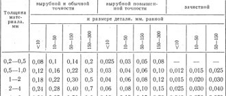
Let's consider setting up a machine for milling through rectangular grooves using disk cutters. When milling rectangular grooves, the width of the disk cutter should be equal to the width of the groove being milled in the case when the runout of the end teeth is zero. If there is runout of the cutter teeth, the size of the groove milled by such a cutter will be correspondingly greater than the width of the cutter.
Setting the cutting depth can be carried out according to the markings. To clearly highlight the marking lines, the workpiece is pre-painted with a chalk solution and indentations (cores) are applied with a center punch on the line drawn with a surface scriber. Setting the cutting depth along the marking line is carried out with trial working strokes. At the same time, make sure that the cutter cuts the allowance only half of the recesses from the center punch.
When setting up a machine for processing grooves, it is very important to correctly position the cutter relative to the workpiece being processed. In the case when the workpiece is installed in a special device, its position relative to the cutter is determined by the device itself.
Precise installation of cutters to a given depth is carried out using special settings or dimensions provided in the device. In Fig. 52 shows diagrams for setting cutters to size using settings. Dimension 1 is a hardened steel plate (Fig. 52, a) or a square (Fig. 52, b), fixed to the body of the device. Between the mounting and the cutting edge of the cutter tooth, a measuring probe 2 with a thickness of 3-5 mm is placed to avoid contact of the cutter tooth 3 with the hardened surface of the mounting. If processing of the same surface is carried out in two transitions (roughing and finishing), then probes of different thicknesses are used to install cutters of the same size.
When processing a batch of identical parts, simultaneous milling of grooves (two or more) can be carried out by a set of cutters.
Grooving
Particularly difficult are the operations of milling angular grooves in the manufacture of cutting tools. In each individual case - when grooves are located at the end, on the cylindrical or conical part of the workpiece - a special configuration of cutters (one- or two-angle) should be selected.
Before milling grooves located on the cylindrical part of the workpiece with a rake angle γ = 0°, the position of the single-angle cutter is set according to the square (Fig. 2, a). The tips of the cutter teeth should touch the outer diametral surface of the workpiece. After this, the tops of the tool teeth are shifted in the transverse direction by a distance equal to half the diameter of the workpiece. You can first mark this line at the end of the workpiece, located on a vertical plane passing through the central axis of the workpiece (Fig. 2, b).
Rice. 2. Scheme of cutter installations when milling grooves of cutting tools:
a, b, c, d – transitions when setting up the machine; D – workpiece diameter; h – milling depth; x – displacement of the cutter end relative to the axial plane of the workpiece
If corner grooves with a rake angle γ˃0 are to be processed, the end of the single-angle cutter is placed at a distance x from the diametrical plane (Fig. 2, c). The required removal is determined by the formula, where D is the diameter of the workpiece:
x = D/(2sinγ),
where D is the diameter of the workpiece
When processing angular grooves with a double-angle cutter, the tool is installed on a square similar to the above, then the tops of its teeth are shifted by a distance x (Fig. 2, d), the formula of which is:
x = D/(2sin(γ+δ) - hsinδ/cosγ),
where D is the diameter of the workpiece, h is the depth of the groove, δ is the angle of the working cutter, γ is the rake angle of the cutter. For a zero value of γ the formula looks like:
x = (D/2 - /0)sinδ
To carry out processing with a two-angle cutter, the workpiece is secured:
- on a mandrel - in the centers of the machine, using a dividing head;
- directly at the centers of the machine, using a dividing head.
In the same way, using double-angle cutters, grooves are cut on the conical surface of the workpieces. Three-jaw chucks are used to secure workpieces. It is also possible to fasten workpieces installed in a mandrel, in the dividing head of the machine spindle, or in the centers of the dividing head and tailstock (if a slight taper is specified).
Machining keyways
To cut keyways (through, open, semi-closed or closed), the workpieces are installed in prisms (depending on the length of the part, one or two prisms are selected for fastening). The design of the prism base includes a special tenon that secures the prism in the groove of the machine table (Fig. 3). The shape of the grooves can be different, in accordance with the shape of the keys, including:
- prismatic;
- wedge;
- segmental, etc.
Rice. 3. Installation of the prism on the machine table
Open grooves located around the circumference can be conveniently cut using disc cutters. The radius of the disk cutter is selected in accordance with the radius of the cut groove.
When the groove is located along the axis of the part, groove backed end (key) cutters are used. If it is necessary to cut segmental grooves, work is carried out using end and attachment cutters, using vertical and horizontal milling machines. The movement of the workpiece is longitudinal, the movement of the cutter is radial, towards the center of the part (Fig. 4).
Rice. 4. Milling keyways:
a – disk cutters with vertical or transverse feed movement; b – key cutters with a pendulum feed movement; Dr – direction of cutting movement; h – milling depth; Da – end mill diameter; t- allowance removed in one pass of the tool
The distance S overcome by the key cutter should be no more than 0.02-0.04 mm/tooth at a speed V of no more than 15-20 m/min. For disc slot cutters, respectively, 0.03-0.06 mm/tooth and 25-40 m/min.
Accurate milling of keyways can be achieved using keyway milling machines. The milling depth when processing on such special equipment ranges from 0.2 to 0.4 mm. The groove is processed in two passes at the same cutting depth, in the forward and reverse directions. This method of milling is called pendulum.
Features of keyway milling
Keyways on shafts are divided into through, open, closed and semi-closed. They can be prismatic, segmental, wedge, etc. (corresponding to the sections of the keys). It is convenient to fix the shaft blanks on the machine table in prisms. For short workpieces, one prism is sufficient. For long shaft lengths, the workpiece is mounted on two prisms. The correct location of the prism on the machine table is ensured with the help of a tenon at the base of the prism, which fits into the groove of the table (Fig. 5.24).
Keyways are milled with slotted disk cutters, backed slotted cutters (GOST 8543-71), keyed cutters (GOST 9140-78) and mounted cutters. The slot or key cutter must be installed in the diametral plane of the workpiece.
Milling of open keyways with a groove exiting along a circle, the radius of which is equal to the radius of the cutter, is carried out using disk cutters. Grooves in which the groove is not allowed to exit along the radius of the circle are milled with end or key cutters.
Sockets for segment keys are milled with shank and attachment cutters on horizontal and vertical milling machines. The direction of feed movement is only towards the center of the shaft (Fig. 5.25, a).
To obtain grooves that are precise in width, processing is carried out on special key-milling machines with pendulum feed (Fig. 5.25, b). With this method, the cutter cuts 0.2...0.4 mm and mills the groove along the entire length, then again cuts to the same depth and mills the groove along the entire length, but in a different direction.
For milling keyways, it is recommended to use keyway cutters with S_= 0.02…0.04 mm/tooth at a cutting speed v = 15… 20 m/min; disc slot cutters with S_ = 0.03… 0.06 mm/tooth at cutting speed v = 25…40 m/min.
An operation similar to slot milling is groove milling
on blanks of cutting tools. The grooves can be located on the cylindrical, conical or end part of the workpieces. Single-angle or double-angle cutters are used as a tool for grooving.
When milling angular grooves on the cylindrical part of a cutting tool with a rake angle γ = 0° using single-angle cutters, the tops of the cutter teeth must pass through the diametrical plane of the workpiece. The cutter is installed using a square (Fig. 5.26, a) in the center of the spindle inserted into the conical hole so that the tops of the teeth of the cutters and the center are aligned, and then the workpiece is moved in the transverse direction by an amount equal to half its diameter, or along the line drawn at the end or the cylindrical surface of the workpiece, passing through its center plane (Fig. 5.26, b).
When processing corner grooves with a given positive value of the rake angle γ, the end surface of a single-angle cutter must be located from the center plane at a certain distance x (Fig. 5.26, c), which can be determined by the formula
x=D/(2sinγ),
where D is the diameter of the workpiece, mm; γ—rake angle,°.
When setting up the processing of angular grooves, the tops of the teeth of a double-angle cutter should be set in the diametrical plane using one of the methods discussed above, and then the workpiece should be shifted relative to the cutter by an amount x (Fig. 5.26, d), which depends on the workpiece diameter D, profile depth groove h, working cutter angle 8 and cutter rake angle γ:
x = D/(2sin(γ+δ) - hsinδ/cosγ).
At γ= 0° x = (D/2 - /0)sinδ.
The workpiece can be installed and secured in one of the following ways: at the centers of the index head and tailstock, or at the centers on the mandrel.
Angle cutters are also used when milling angular grooves on a tapered surface. The cutters are installed relative to the diametrical plane of the workpiece in the same way as when milling angular grooves on a cylindrical surface.
When milling angular grooves on a conical surface, the workpiece can be secured in a three-jaw chuck, on an end mandrel inserted into the tapered hole of the index head spindle or into the centers of the index head and tailstock. The last of the listed methods for installing the workpiece is used with a small taper angle.
How to mill shoulders
The formation of ledges on workpieces of various parts can be successfully performed on vertical and horizontal milling machines. The technological map for manufacturing parts may provide for the use of various types of cutters, depending on the required shape and size of the part, and its surface area. When the surface being machined is large in size, preference is given to end mills (Fig. 5, d). In other cases, disc and end mills are used. To simultaneously process two shoulders on one part, use a set of disk cutters mounted on one cylindrical mandrel (Fig. 5, a-c).
The disk cutter must be selected in such a way that the width of the shoulder being processed is 5-6 mm less than the width of the cutter; this will facilitate processing and ensure the calculated accuracy of the surface.
Rice. 5. Scheme for processing ledges:
a – disk cutters; b – end mills; c – a set of cutters; d – end mills; Dr – direction of cutting movement
A disk cutter with large (or normal) teeth is used for milling materials that can be easily processed. In this case, you can set a larger cutting depth. Parts made from difficult-to-cut materials are milled using tools with fine or normal teeth.
In cases where two shoulders are located symmetrically on a part, they can be processed alternately using machines with two-position rotary tables. To do this, after processing the first ledge, the table is rotated along with the part attached to it by 180° and the next ledge is processed.
Milling with end mills.
In this article we will focus on some theoretical and empirical aspects of the issue of milling work. In particular, the article addresses the problems of high quality, productivity and low cost of metalworking when milling with end mills.
First of all, let's determine the type of processing. The choice of tools and cutting modes depends on the type of processing, so you need to choose the appropriate one. For example, with rough milling, dimensional accuracy and surface quality are not fundamental features, unlike pure milling. It should be borne in mind that not a single milling process is complete without a collet.
Several factors that influence the efficiency of the face milling process are discussed below.
Selecting a Face Mill Body
Imported end mill bodies are quite expensive; for example, an imported end mill body with a diameter of 100 mm can cost more than 15,000 rubles. Therefore, the choice of case should be taken seriously.
Insert pitch is one of the most important parameters of an end mill.
For example, a face mill with a diameter of 100 mm with a coarse pitch may have 5 inserts, a medium – 7 inserts, and a fine – 10 inserts. Different manufacturers provide different numbers of plates for a given pitch. In addition, a lot also depends on the design of the cutter.
Equipment with low cutting force rigidity may vibrate excessively during rough milling. Such vibrations can reduce tool life and damage the spindle.
If the durability of the tool decreases, characteristic features appear - chipping. Such chipping can break the insert and then the cutter body.
If you use cutters with large insert pitches, then the power of the machine and the cutting force can be reduced.
It is recommended to use such cutters for roughing on machines equipped with spindles with tapers 30 and 40. Cutters with large insert pitches are also necessary for processing materials with drain chips. In this case, there is much more space for the chips, and the likelihood of them being cut again is almost zero.
Finish milling is a completely different process. The depth of cut (about 0.25-0.5 mm) and feed per tooth (about 0.05-0.15 mm/tooth) are much smaller compared to rough milling.
High power of the machine, as for rough milling, is not needed, which means you can use end mills with fine plate pitches. The more plates, the higher the minute feed of the table during processing, but the feed rate per cutter tooth is low. Shallow cutting depths also tend to eliminate chip placement problems.
The power of the machine is closely related to the speed and quality of the spindle.
Insert selection
The choice of inserts depends on the type of processing.
In some cases, you should choose ground inserts (with greater accuracy and sharpness of the cutting edge), and in some cases, unground inserts.
For rough milling, it is recommended to use unground inserts. Due to the fact that their cutting edge is equipped with a protective chamfer. This chamfer makes the edge stronger when machining at higher cutting depths and feeds.
At the same time, they are cheaper compared to ground plates.
As a rule, unground inserts do not provide the same precision and surface quality as ground ones.
This can be explained by the low accuracy of the plates themselves. They have different offsets relative to the cutter body. For finishing milling, it is recommended to choose ground inserts with high dimensional accuracy and good surface quality.
The geometry of the front surface of the ground inserts is highly sharp, which is necessary to ensure the cutting process at a small milling depth. If the edge is not sharp enough, the metal is plastically deformed. The quality of the machined surface deteriorates, and the wear resistance of the tool decreases.
To ensure high surface quality during milling operations, it is best to use wiper plates (Wiper technology). One stripper is installed in the cutter body along with conventional inserts, protruding from the body in the axial direction. This improves the quality of the processed surface. Wiper technology is also used in the production of turning, parting and grooving tools.
Wear-resistant coatings and coolant
When it comes to using coolant in milling, experts disagree.
Considering the size of the cutting zone, providing an abundant supply of coolant with a large-diameter cutter is labor-intensive.
Temperature fluctuations can lead to thermal cracks and insert failure, and possible damage to the cutter body.
Nowadays, tool coatings have been developed that allow milling without coolant with minimal risk of thermal cracks. Some coatings, such as TiAIN, harden as the temperature increases.
Because when milling without coolant, the operator can observe the process of chip formation, in particular, sees its shape and color, and based on these characteristics makes a conclusion about the correct choice of cutting mode. Therefore, dry milling is preferable.
Different materials have different composition, density and structure, so they react differently to thermal influences.
For example, when cutting carbon steel at the correct speed, brown chips will actually be produced. The temperature rises, and then the carbon enters into a chemical reaction with oxygen from the air, and the chips acquire a blue color - this is what we see as a result of processing. Black chips indicate the need to reduce the cutting speed because the temperature in the cutting zone is too high. Stainless steels have a low thermal conductivity coefficient, and heat transfers poorly into chips. When processing stainless steel at optimal conditions, the chips have a light brownish tint. If the chips turn dark brown, reduce the cutting speed.
The speed can be adjusted using the spindle.
To prevent the formation of built-up edges when processing stainless steel, a certain amount of heat is still required, the release of which is achieved by selecting the optimal cutting speed.
The cutting edge is easy to damage. For example, during the coolant process, chips are cooled too quickly. The material of the part sticks to the cutting edge and then breaks away from it, causing damage. The feed rate must be precisely adjusted, since a high feed leads to build-up, and at a low feed, plastic deformation of the workpiece may occur.
When milling without coolant, it is extremely important to select the optimal cutting mode. Then the main part of the heat goes into the chips.
But when processing flammable materials such as magnesium, it is better to use coolant, and it is necessary to have fire safety equipment nearby, such as a fire extinguisher.
If you are machining dry material, apply a small amount of lubricant to the insert seating surfaces and screws. Apply carefully as too much grease may cause insertion errors.
Up and down milling
Most face milling operations performed on non-rigid milling machines are performed using the up-milling method (cutting speed and table feed are directed in different directions). Therefore, it is recommended to use the climb milling method (cutting speed and table feed have a common direction).
During up milling, the cutting process begins without load on the cutting edge, so plastic deformation of the workpiece material occurs and its hardening, and as a result, severe wear of the inserts. Down milling does not have this disadvantage.
When using climb routing, set the routing width to about two-thirds the width of the cutter. In this case, when inserting the plates, plastic deformation of the workpiece material will not occur.
Vary the routing width and try to determine experimentally which ratio between cutter diameter and routing width is optimal for a particular machine and cutter. In the process of measuring this ratio, the roughness of the machined surface will change.
By reducing the milling width to half the cutter diameter, you also provoke plastic deformation of the workpiece material due to a decrease in chip thickness. In this case, it is recommended to increase the feed per tooth of the cutter; in this case, tool life and productivity will increase. When finishing milling, the feed rate is adjusted to the required surface quality.
Result evaluation
To evaluate the performance of face milling, when comparing options, calculate the volume of material removed per unit time while achieving acceptable results in terms of quality. To do this, you need to multiply the milling width, milling depth and minute feed of the table. The result is a value with the dimension mm3/min.
There are many types of end mills, so choose them carefully. It is best to contact specialists in the field of tools and metalworking technology, then you will not waste time and money in vain.
Cutting blanks. Deep Grooving
Cutting off parts of workpieces and cutting deep grooves is carried out using cutting (slotting) cutters. When performing these operations, it should be remembered that choosing a thin cutter with a large diameter can lead to curvature and disruption of the shape of the workpiece being cut. This is due to the reduced rigidity of the cutter, therefore, when selecting a cutting (slotting) tool, preference should be given to a tool with the smallest possible diameter. The cutting speed, which is different for cutting workpieces made of different materials, is also taken into account. Thus, for cutting steel parts, the cutting speed ranges from 24 to 60 m/min, for gray cast iron – from 12 to 65 m/min, for malleable cast iron – from 27 to 75 m/min.
Parts are secured when cutting, usually in a vice. Sheet metal is cut using a feed S of 0.01 to 0.08 mm/tooth. The cutter material is high-speed steel.
Rice. 6. Cutting blanks:
Dr – direction of cutting movement