Assembly and welding accessories
For more productive and high-quality production of welded structures, special devices for assembly and welding are used:
- universal clamp for mounting and assembling cylindrical parts;
- manual clamp for assembling profile and sheet metal;
- manual spring clamp for assembling profile metal;
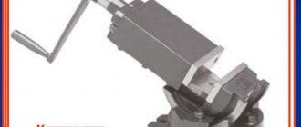
- rotary screw clamp for assembly and fastening of parts in mass production;
- clamp for assembling parts of different profiles;
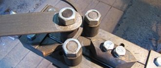
- corner clamp made of bolts for assembling large structures from sheet metal;
- tack bracket with a crowbar for structures that are assembled overlapping in installation conditions;
- comb on tacks for large sheet structures;
- tack washers with strips and wedges for sheet structures;
- screw tie for attracting parts;
- compression ring for large diameter pipelines;
- flexible clamp with eccentric clamp for cylindrical parts;
- screw expansion and tension mechanism for sheet structures and flat products;
- a hook with a crowbar for tightening the edges;
- screw spacer for cylindrical parts;
- spacer for assembling parts of mechanical engineering structures;
- screw stop bracket for parts of limited dimensions;
- one-sided screw stop for assembling truss profiles and other structures;
- one-sided stop for assembling structures at stationary posts.
Marriage during marking
First of all, when marking, defects that were made at previous stages of production emerge. Products from procurement sites or workshops, as well as materials purchased from other enterprises, reveal:
- violation of dimensions
- shape distortion
- warping.
Such castings or rentals are not subject to further marking operations, but are returned to the department or organization that caused the defect to correct it.
At the marking stage itself, defects can be caused by the following factors:
- Inaccurate drawing. The mechanic, without hesitation, displays incorrect dimensions on the part, and during further processing, defective products come out.
- Inaccuracy or malfunction of instruments. All marking tools are subject to mandatory periodic verification by the metrological service of the enterprise or an authorized metrological center.
- Incorrect use of tools or marking accessories. There are known cases when instead of calibrated measuring pads, ordinary pads were used to set the level. In this case, erroneous application of angles and slopes is also possible.
- Inaccurate placement of the workpiece on the marking table or plaza. They lead to distortions when setting aside dimensions, violation of parallelism and coaxiality.
- Wrong choice of reference planes. It is also possible that some of the dimensions were applied from the base planes, and some from the rough surfaces of the workpiece.
Marriage during marking
Separately among the reasons for defects are the marker's errors. These include:
- Incorrectly read drawing. It is possible to apply a radius instead of a diameter and vice versa, inaccurate application of the centers of holes relative to the center marks, etc. If any difficulties arise, the mechanic must seek clarification from the foreman or foreman.
- Carelessness and inattention when punching and drawing lines.
Negligence can be committed by both the mechanic himself and his supervisors, who did not check the tool on time or issued inappropriate marking devices.
Typically, marking operations are entrusted to the most experienced and responsible workers, counting on the fact that they will not mechanically transfer dimensions from the drawing to the workpiece, but will treat the matter thoughtfully and promptly notice and eliminate the reasons for possible defects on their own or by contacting their managers.
Auxiliary tools for marking
The high degree of accuracy of the marking operations performed depends not only on the tool used, but also on the conditions under which the work process is carried out. To improve the convenience and quality of such activities, vertical posts, special jacks, linings, rotating and dividing devices, headstocks for centering, etc. are used. The main devices of this kind include a marking plate that imitates a plane. On this platform you can perform planar and spatial markings, as well as paint.
§ 34. Marking parts made of metal sheet and wire
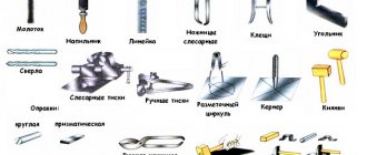
After editing, the contours of the future product are marked on the workpiece. Marking is carried out using marking tools: a scriber, a marking compass and a center punch using a metal ruler or square (Fig. 125).
Rice. 125. Marking tools: a - ruler; b - square; c - scribers; g - center punch; d - marking compass
The scriber is a sharpened metal rod and is used to apply marking lines (scores) to the workpiece.
Circles and arcs are drawn using a marking compass. The radius of a circle or arc is first plotted using a ruler.
By hitting the center punch with a hammer, holes are made on the surface to be marked, marking the centers of future holes.
When marking out parts according to a template, try to cut the material rationally, that is, so that the amount of waste is minimal.
This problem can be quickly and accurately solved on a computer. To do this, the part template and the metal sheet are drawn to scale. By moving and rotating the template, copying it repeatedly, you can achieve the optimal (best) arrangement of parts on the sheet.
Figure 126 shows a drawing of the “eyelet” part, made of thin steel sheet and used for hanging wall panels. The value S 0.8 in the drawing means that the sheet thickness is 0.8 mm.
Rice. 126. Drawing of the “eye” part
Marking begins with drawing contour lines of the part and lines of symmetry with a scriber, then drawing the center lines of holes and arcs, drawing circles and arcs with a compass. Finish the marking by marking the centers of the holes.
A development is a flat image of a part blank (for example, a box), which becomes three-dimensional when bent. The reamer is marked according to the drawing, and then a flat part blank is cut out.
The layout is marked using a ruler and a metal square, starting from the base (largest) sides, then the other sides are measured and outlined, and center lines and fold lines are drawn.
Practical work No. 36 Marking parts made of metal sheet and wire
Work order
- Prepare your workplace, tools and workpieces for marking.
- Mark blanks for making parts and products from thin metal sheet and wire (preferably for your creative project).
- Check the markings are correct.
Control questions
- What is marking called and why is it done?
- What tools are used for marking?
- How to mark products made of metal sheet and wire?
- What is called a sweep?
- In what sequence are the scans marked?
General concepts
Marking is the operation of applying marking lines to the workpiece being processed, defining the contours of the future part or place to be processed.
The accuracy achieved with conventional marking methods is approximately 0.5 mm. With precise marking, it can be increased to hundredths of a millimeter.
Planar marking , usually performed on the surface of flat parts, on strip and sheet material, consists of applying contour parallel and perpendicular lines (marks), circles, arcs, angles, axial lines, various geometric shapes according to given dimensions or contours of various holes according to templates.
Spatial marking is most common in mechanical engineering; in its techniques it differs significantly from the planar one.
What is markup
The operation of applying the dimensions and shape of a product to workpieces is called marking. The purpose of the operation is to designate the places where the part should be processed and the boundaries of these actions: drilling points, bend lines, weld lines, markings, etc.
Marks are scratched into the metal surface with a sharp tool or applied with a marker. Cores are filled with a special tool - a center punch.
According to the method of execution, there are such types of markup as:
- Manual. It is made by mechanics.
- Mechanized. Performed using mechanization and automation tools.
Based on the application surface, they are distinguished
- Superficial. It is applied to the surface of the workpiece in one plane and is not associated with the lines and marking points applied to other planes.
- Spatial. It is carried out in a unified three-dimensional coordinate system.
Notes on straightening and marking for thin sheet metal
The choice between surface and spatial markings is determined, first of all, by the complexity of the spatial configuration of the part.
Plane marking tool
A distinctive feature of a tool designed to perform measurements and marks in one plane is that it is tailored to basic geometric calculations. With the help of such devices, the user indicates the boundaries of contours, interaxial distances, marks marks, and records angular deviations. Similar actions are performed by spatial marking models, but they are distinguished by minimal productivity when working on one plane. So, the flat group of tools of this type includes a bench square, various scribers, protractors, rulers, etc. It is important to note that such operations also require auxiliary devices that are not directly related to measurements and markings. For example, stops and conductors are used in this capacity.
Actions of this kind are not always primary when performing architectural and design activities. Such a tool is also used in checking existing structures. If adjustments need to be made, then, for example, a metal scriber or a graver can be used. It will allow you to accurately construct points along which a new structure or object will be installed in the future.
Bending
There are limitations due to the fragility of metals. The bend radius must exceed the thickness of the profile or part by 25 times, otherwise cracking and breaks are possible. Thick-walled workpieces cannot be dealt with using the cold method; hot deformation methods are used in production or forge conditions. Edge processing is not done before hot deformation; the parts are finished after bending.
Achieving the exact bend angle manually is difficult. This is a mechanized stage of metal preparation. Sheet metal is passed through bending rollers and bending machines. Cold bending is used after preliminary preparation of products for welding: removing edges, marking, drilling holes, if they are in the drawings or needed for assembling the structure.
Thick strips are passed successively through 3-roll or 4-roll machines. Straightening presses are used to shape the profile.
The bend radius must exceed the thickness of the profile or part by 25 times
Applying marks
The standard regulates the procedure for drawing marking lines:
- horizontal;
- vertical;
- inclined;
- curvilinear.
Applying curved elements after straight ones provides another opportunity to check their accuracy. The arcs must close the straight lines, the interface must be smooth.
Direct marks are carried out with a well-sharpened scriber, without tearing off, in one step. At the same time, the scriber is tilted away from the ruler or square so as not to introduce distortions.
Parallel lines are drawn using a square and moving it along the reference ruler to the required distance.
Applying mutually perpendicular and parallel marks
Applying marks at an angle to each other
If the workpiece already has holes, then a special tool, a center finder, is used to attach marking lines to them.
In order to mark inclined lines, use a marking protractor with a hinged ruler fixed at its zero point.
For particularly precise markings in plumbing, calipers are used. They allow you to measure distances and scratch marks with an accuracy of hundredths of a millimeter.
Tools for marking
In essence, any marking means applying an in-depth contour or dot notch. This function can be performed by a wide range of tools, including drawing devices, gauges and standard gauges, spring-type compasses and a core - a tool that is the simplest representative of this group. On the contrary, multifunctional devices implement the tasks of marking as auxiliary ones. These include, for example, models that allow you to find and center parts. These are special types of cores, squares, protractors, etc.
§ 20. Workplace for manual metal processing
As you already know, it is convenient to process wood parts on a carpentry bench. To process metal workpieces, it is also necessary to organize a similar workplace.
Manual processing of metals is called metalworking. The workplace for manual metal processing in the school workshop is a metal workbench (Fig. 92).
Rice. 92. Mechanic's workbench: 1 - base; 2 — tool boxes; 3 - vice; 4 - cover; 5 - protective mesh
It consists of a base 1, a cover 4, on which a bench vice 3 is attached. The workbench has tool boxes 2 and a protective mesh 5. Sometimes metalwork work is performed on a universal workbench, which is both a metalworker and a carpenter (Fig. 93).
Rice. 93. Universal workbench: 1 - base; 2 — seat; 3 - cover; 4 - vice; 5 — protective mesh; 6 — stand for technical documentation
Before starting work, you should check whether the bench fits your height. To do this, you need to stand next to the workbench, with your arms down, bend one arm at the elbow at a right angle and place your palm on the top of the vice. If at the same time the arm does not bend or extend, it means that the height of the workbench corresponds to your height (see Fig. 16). Otherwise, you need to contact the teacher, and he will adjust the height of the universal workbench to suit the student’s height using a special device located under the lid.
In order to process a metal workpiece, it is secured in a bench vice (Fig. 94). The base plate 1 of the vice is attached to the workbench cover. By rotating the lead screw 2 using the handle 3 clockwise, the movable jaw 6 is brought closer to the fixed jaw 4 and thus the workpiece is compressed. To securely fasten the workpiece, a cross-shaped notch is applied to the surface of the clamping bars 5.
Rice. 94. Bench vice: 1 - support plate; 2 — lead screw; 3 — clamping handle; 4 - fixed sponge; 5 — clamping strips with a notch; 6 — movable sponge; 7 — fixing handle
If necessary, the upper part of the vice can be rotated at a certain angle relative to the base plate and secured in this position with a locking handle 7.
In order not to damage the surface of the soft metal workpiece being clamped, corners (lips) made of copper or aluminum are put on the jaws (see Fig. 95).
Rice. 95. Fastening a soft metal workpiece in a vice: 1 - jaws; 2 - blank
Basic tools for manual processing of thin sheet metal and wire are shown in Figure 96.
Rice. 96. Tools for manual processing of thin sheet metal and wire: a - chisel; b - plumber's hammer; c - mallet; g - hacksaw; d - metal scissors; c - file
Safe work rules
- Place on the workbench only those tools that are necessary for this type of work.
- Do not damage the bench cover with cutting tools.
- When securing a workpiece in a vice, do not hit the vice handle with a hammer.
- At the end of the work, remove metal shavings from the workbench cover and vice only with a special brush.
Getting to know the professions
A mechanic is a specialist in manual metal processing. He is well versed in the properties of metals and performs marking, cutting, bending, drilling, welding, stripping, and joining metal workpieces. A mechanic knows how to sharpen and prepare metal-cutting tools for work.
Practical work No. 18
Familiarization with the structure of a bench and vice
- Familiarize yourself with the design of the metalworking (universal) workbench available in the school training workshop. Find the base, cover, protective mesh, vice.
- Study the structure of a bench vice and fill out the table in your workbook.
- Determine whether the workbench is suitable for your height.
- Practice securing metal workpieces made of thin sheet metal and wire in a vice. When releasing a workpiece clamped in a vice, hold it with your hand so that it does not fall.
Testing your knowledge
- Name the main parts of a metalworking (universal) workbench.
- Compare the designs of metalworking and universal workbenches: how are they similar?
- What are the main parts of a bench vise?
Tools for planar marking
Work should be performed on a flat and comfortable surface. For this purpose, marking tables are used:
- wooden;
- metal.
Basic requirements for the quality and design of tables:
- Strength and stability. To ensure strength, the table legs are connected by horizontal bars. It is recommended to install large-scale marking plates on jacks.
- Sufficient working surface area. Standard tables have the following dimensions: length 2000–3000 mm; width 4000–5000 mm; height 700–1000 mm. The surface area of the table must correspond to the size of sheets, tapes, strips of material.
- Convenience. Tables are equipped with various devices:
- weights for fixing sheets of light material;
- prisms for installing pipes;
- clamps for securing metal sheets;
- rectangular and wedge-shaped gaskets for installing profiles and other parts.
The workplace must be provided with all the tools necessary for planar marking. The table provides a list of necessary tools and some recommendations for working with them.
| Tool | Function | Design requirements | Recommendations for use |
| Scriber | drawing marking lines on workpieces | · thin steel rod; · one end is sharpened at 45 degrees, the other is bent into a ring; · the sharp end is hardened | · to obtain thin marks, the tip must be hard and sharp; · when working, the scriber is deflected from the ruler in the direction of its movement; it must be constantly pressed against the ruler with its tip |
| Outline | drawing contours parallel to the edges of the sheet | · material: copper or steel; presence of a graphite pencil in the working part | Before applying marking marks, the evenness and accuracy of the edges along which the tool will move is checked |
| Reismus | · checking the location of workpieces; · carrying out parallel risks | · stand with scriber fixed at the required height; · fixation height is measured with a square | |
| Kerner | · construction of centers of circles or holes; · drawing holes on the marking lines | · material - hard steel; · dimensions: diameter 8-13 mm, length 90-150 mm; · the end is sharpened at 60 degrees; · there are manual and automatic (set marks of the same size) | The automatic center punch does not require a hammer to operate |
| Locksmith's hammer | percussion tool for punching | use hammers weighing 50 - 200 g | the work is performed with light movements conveyed by bending the hand “from the shoulder” |
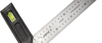
| Squares | · construction and control of angles; restoration of perpendiculars | preferred material - metal | · it is advisable to have squares with angles of 30, 45, 60 degrees; · a square with a shelf is used to check the correct placement of parts on the plate |
| Protractor with protractor | marking corners and checking mark alignment | preferred material - metal | The position can be fixed with a hinge screw |
| Compass | · construction of circles, arcs; Transfer of dimensions from ruler to workpieces | It is recommended to harden the legs of the compass | the tip of the compass is installed strictly in the punched hole |
| Marking plate | Serves as a working surface; · used for equipment storage | · located horizontally; · must be clean and dry | placed on cabinets, stands with drawers, tables |
| Templates, stencils | simplification and acceleration of marking of similar parts | durable steel templates | ensure a tight fit of the template to the workpiece |
| Vise | tool for securing small parts | ensuring smooth tightening efforts | For fine work, a small step is recommended; for coarse clamping, a wide step is recommended. |
Marriage when marking
First of all, when marking, defects that occurred at previous stages of production emerge. Products from procurement sites or workshops, as well as materials purchased from other companies, are found:
- violation of dimensions
- shape distortion
- curvature
Such castings or rentals are not subject to future marking operations, but are returned to the department or organization that caused the defect to correct it.
At the actual marking step, defects can be caused by the following factors:
- Drawing error. The mechanic, without thinking, displays the wrong dimensions on the part, and during subsequent finishing, defective products come out.
- Error or breakage of instruments. All marking tools are subject to mandatory periodic verification by the metrological service of the enterprise or an authorized metrological center.
- Incorrect use of tools or additional markings. There are known situations where instead of calibrated measuring pads, ordinary pads were used to set the level. In this case, incorrect application of angles and slopes is also possible.
- Error in installing the workpiece on the marking table or plaza. They lead to distortions when setting aside dimensions, violation of parallelism and coaxiality.
- Incorrect choice of reference planes. It is also possible that some of the dimensions were applied from the base planes, and some from the rough surfaces of the workpiece.
Marriage when marking
Separately among the reasons for defects are the marker's errors. These include:
- Misread drawing. It is possible to apply a radius instead of a diameter and vice versa, inaccurate application of the centers of holes relative to the center marks, etc. When difficulties arise, the mechanic must seek an explanation from the foreman or foreman.
- Sloppiness and negligence when punching and drawing lines.
Inattention can be caused by both the mechanic himself and his supervisors, who did not check the tool in a timely manner or issued unsuitable marking devices. https://www.youtube.com/embed/VCBykZSMw9Q
In most cases, marking operations are entrusted to the most experienced and responsible employees, counting on the fact that they will not mechanically transfer dimensions from the drawing to the workpiece, but will treat the matter thoughtfully and promptly notice and eliminate the reasons for the expected defects without outside help or by contacting their own managers.
If you find an error, please select a piece of text and press Ctrl+Enter.
Spatial marking.
| Rice. 12. Spatial marking techniques: a – applying paint to a workpiece mounted on a prism; b – finding the center of the hole in the workpiece; c – applying marks to the workpiece; d – marking a workpiece mounted on a marking device (box) |
Spatial marking is used for graphic constructions carried out on the surface of volumetric parts located in different planes at different angles to each other.
The difficulty of spatial marking lies in the fact that you have to not only mark individual elements on one surface (side) of the part, but also link the markings of these individual surfaces (planes, axes of holes, their alignment, angles of inclination, etc.) with each other. Spatial marking is carried out on a marking plate by installing and securing the workpiece on it in such a way that each plane or axis of the part is parallel or perpendicular to the general plane of the marking plate. To install and align workpieces on the marking plate, various prisms, support spacers, jacks, marking cubes and special (often rotating) devices are used. Installation of the workpiece on the plate is carried out as follows. When installing, only the first position of the workpiece on the plate is independent, and all other positions depend on the first. It is chosen so that it is convenient to start marking from the selected base, parallel to the plane of the marking plate. The workpiece is installed in the required position using pads, wedges, jacks or directly on the plane of the slab, on squares, marking boxes, prisms. The installation must be firm (no rocking).
The methods of spatial marking (Fig. 12, a, b, c, d) basically coincide with the methods of projection technical drawing. The procedure for applying marks and markings for spatial markings is the same as for planar markings.
When marks are applied, the workpiece remains motionless, and the surface gauge or height gauge moves relative to it along the marking plate. Risks are carried out one time. Marking lines are applied in the following order: first draw all horizontal marks on all four or two opposite sides of the workpiece, then vertical ones and finally all circles, arcs, mates, shaped and inclined lines.
In addition to the main marking marks, control marks are carried out parallel to them at a distance of 5-7 mm, which serve to check the installation of the workpiece on the machine during further processing, as well as for the possibility of processing in cases where the marking mark has somehow disappeared.
Basting using templates.
When producing a batch of identical parts, markings using templates are used - basting. In this case, a template is made from sheet steel, the configuration and dimensions of which exactly match the part. Then the template is applied to the surface of the workpiece prepared for marking and its contour is traced with a scriber. Then cores are applied along the marks.
| Rice. 13. Marking according to a template |
To mark shaped metal, linear templates are used, with the help of which, simultaneously with marking the contour of the part, the centers of future holes are marked.
Comprehensive pattern marking of horizontal and vertical lines, as well as internal or external contours on workpieces intended for mass production, greatly simplifies and speeds up work.
Increased productivity is achieved due to the fact that the dimensions of the part are transferred by applying a template to the surface of the workpiece or hanging (installing) them on special racks.
§ 34. Marking parts made of metal sheet and wire
After editing, the contours of the future product are marked on the workpiece. Marking is carried out using marking tools: a scriber, a marking compass and a center punch using a metal ruler or square (Fig. 125).
Rice. 125. Marking tools: a - ruler; b - square; c - scribers; g - center punch; d - marking compass
The scriber is a sharpened metal rod and is used to apply marking lines (scores) to the workpiece.
Circles and arcs are drawn using a marking compass. The radius of a circle or arc is first plotted using a ruler.
By hitting the center punch with a hammer, holes are made on the surface to be marked, marking the centers of future holes.
When marking out parts according to a template, try to cut the material rationally, that is, so that the amount of waste is minimal.
This problem can be quickly and accurately solved on a computer. To do this, the part template and the metal sheet are drawn to scale. By moving and rotating the template, copying it repeatedly, you can achieve the optimal (best) arrangement of parts on the sheet.
Figure 126 shows a drawing of the “eyelet” part, made of thin steel sheet and used for hanging wall panels. The value S 0.8 in the drawing means that the sheet thickness is 0.8 mm.
Rice. 126. Drawing of the “eye” part
Marking begins with drawing contour lines of the part and lines of symmetry with a scriber, then drawing the center lines of holes and arcs, drawing circles and arcs with a compass. Finish the marking by marking the centers of the holes.
A development is a flat image of a part blank (for example, a box), which becomes three-dimensional when bent. The reamer is marked according to the drawing, and then a flat part blank is cut out.
The layout is marked using a ruler and a metal square, starting from the base (largest) sides, then the other sides are measured and outlined, and center lines and fold lines are drawn.
Practical work No. 36 Marking parts made of metal sheet and wire
Work order
- Prepare your workplace, tools and workpieces for marking.
- Mark blanks for making parts and products from thin metal sheet and wire (preferably for your creative project).
- Check the markings are correct.
Control questions
- What is marking called and why is it done?
- What tools are used for marking?
- How to mark products made of metal sheet and wire?
- What is called a sweep?
- In what sequence are the scans marked?
Devices for planar marking
To carry out markings, marking plates, pads, rotating devices, jacks, etc. are used.
on the marking plate and all fixtures and tools are placed. The marking plate is cast from fine-grained gray cast iron.
The size of the slab is chosen so that its width and length are 500 mm greater than the corresponding dimensions of the workpiece to be marked. Large slabs, for example 6000 x 10,000 mm, are made in composites of two or four slabs, which are fastened with bolts and dowels.
The surface of the stove must always be dry and clean. After work, the slab is swept with a brush, thoroughly wiped with a rag, greased with oil to protect against corrosion and covered with a wooden shield.
The flatness of the marking plates is checked using an accurate straight edge and a feeler gauge (or tissue paper). The working surfaces of scraped slabs intended for precise marking are checked for paint using a straight edge. The number of spots in a 25 x 25 mm square must be at least 20.
Read also: Stand for eyelashes reviews
Before starting marking, the workpiece is installed and aligned on the marking plate, using support pads, prisms and jacks of various designs.
The pads are used to ensure the correct installation of parts when marking, as well as to protect the marking plates from scratches and nicks. The simplest phenomena are flat support pads
.
Linings of large sizes are made of hollow cylindrical, prismatic, I-section
, etc.
Wedge pads are two joined, precision machined steel wedges. The movement of the wedge per division is 0.1 mm.
Jacks are used to install bulky and heavy workpieces; they allow you to cut and adjust the position of the marked workpieces in height.
Ordinary jacks - in the body of which there is a screw with a rectangular thread; heads of various shapes are attached to the upper end of the screw. The workpiece is raised and lowered by rotating the screw.
The roller jack makes it possible not only to adjust the position of the workpiece in height, but also to freely rotate it in the horizontal plane, which is necessary when marking heavy workpieces.
Retractable centers are used for marking cylindrical parts.
Scribblers (needles) are used to draw lines (scores) on the surface to be marked using a ruler, square or template. Scribblers are made from tool steel U10 or U12.
A scriber with a bent end is a steel rod sharpened on both sides, one end of which is bent at an angle of 90 degrees. The middle part of the scriber is thickened and knurled for convenience. The bent end is used to apply marks in hard-to-reach places.
The scriber with an insert needle is made like a watch screwdriver; Hardened and sharpened steel rods can be used as an insertion needle.
The pocket scriber is made in the form of a pencil with a retractable tip. A rod made of VK6 hard alloy is soldered onto the working tip, sharpened to a cone at an angle of 20 degrees.
The scribers must be sharp; the sharper the scribers, the thinner the marking mark will be and, therefore, the higher the marking accuracy.
A center punch is a metalworking tool used for making indentations (cores) on pre-marked lines (cores are made so that the marks are clearly visible and are not erased during the processing of the part). Cores are made from tool carbon or alloy steel U7A, U8A, 7HF or 8HF. There are ordinary, special, spring (mechanical), electric, etc. cores.
An ordinary punch is a table rod with a length of 100, 125 or 160 mm and a diameter of 8, 10 or 12 mm, respectively; its firing pin has a spherical surface at an angle of 50...60 degrees, and with precise markings it is sharpened at an angle of 30...45 degrees.
The use of a special punch for punching small holes and rounding small radii
significantly improves markup quality and productivity.
The core for step marking consists of two cores - the main and auxiliary, fastened with a common bar. The distance between them is adjusted by a bar depending on the pitch of the holes being marked.
Compasses are used for marking circles and arcs, dividing segments and circles, as well as for geometric constructions. Compasses are also used to transfer dimensions from measuring rulers to a part.
Marking compasses are simple
or with
an arc, precise
and
spring
. A simple compass consists of two hinged legs - whole or with inserted needles; the desired leg solution is fixed with a screw.
Calipers . Marking calipers are designed for precise marking of straight lines
and
centers
, as well as for
marking large diameters.
Reismas . Reismus is the main tool for spatial marking and is used for drawing parallel, vertical and horizontal lines, as well as for checking the installation of parts on the slab. For more accurate markings, a surface gauge with a micrometric screw is used.
Cutting methods
There are several ways to separate material. The technology depends on the equipment used in the work process. The following types of metal cutting are distinguished:
- manual;
- waterjet;
- thermal.
Manual metal cutting
Manual cutting of metal is not highly efficient and is not used on an industrial scale. The following tools are used for manual cutting:
- scissors;
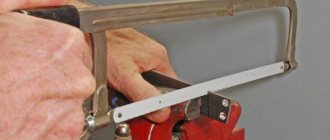
- hacksaw;
- jigsaw;
- Bulgarian.
Waterjet cutting of metal
The waterjet cutting method is based on the impact of a jet of water mixed with abrasive particles on the workpiece. The pressure of the supplied liquid is 5000 atm. The advantage of this type of metal cutting is the ability to obtain a variety of lines. Alloys of a certain grade with a small sheet thickness are processed.
Thermal cutting of metal
Hot cutting of metals is based on the absence of contact between the tool and the workpiece. The hot jet melts and separates the material in the right place.
Types of thermal cutting include:
- oxygen gas;
- laser;
- plasma.
Oxygen gas cutting
Oxy-fuel cutting consists of 2 stages:
- A jet of flame is directed to the cutting site, which comes out of the cutter. Acetylene is used as a flammable material.
- After heating, oxygen is supplied, which cuts through the softened metal surface. At the same time, oxides are removed.
During operation, the distance from the bottom point of the cutter to the surface of the product must remain constant. The quality of the cut depends on this.
Laser cutters are used for this purpose. The process is based on delivering a laser beam to a point on the surface. Thermal energy is focused. The area is heated, the material melts and then evaporates. As the beam moves, it cuts the surface.
Laser cutting of metal
Plasma
A plasmatron is used as equipment for plasma cutting. Oxygen comes out through the nozzle in it under high pressure. Its temperature is up to 20 thousand degrees. Beam width 3 mm. The surface area is heated, partially burns out, and the melt is blown out.
Mechanical metal cutting
Mechanical cutting of metal is carried out using special steel with a high degree of hardening. Due to its high hardness, the tool cuts the product.
The following types of equipment are used for cutting:
- band-saw;
- guillotine;
- disk machine.
Band saw cutting
A band saw is a blade that is fixed in special equipment. The material of the tool is the same as that of a hand-made product. There are teeth on one side. During operation of the machine engine, the pulleys rotate, due to which the belt moves continuously.
During operation there is a slight waste, because the width of the blade is 1.5 mm. It is possible to cut both sheet metal and round workpieces.
Impact cutting of metal on a guillotine
Guillotine metal cutting is used to prepare sheet steel blanks for stamping operations. The fabric to be cut is placed on a horizontal surface, fed all the way and cut with guillotine shears across the entire width in one blow.
Cutting on a disc machine
A disk is used as a working tool. There are teeth along its outer surface. There is a protective casing on top. An electric motor is used as a drive, which rotates the disk. The result is a high quality cut.
Pipe cutters are used to cut pipes using the same principle. During the work process, the workpiece is constantly rotated 360 degrees. It is possible to make cuts at different angles.
Planar marking – Plumbing
Planar marking can be done by direct drawing, using a template (which consists of placing a template on the part to be marked and drawing on it, followed by marking the contours of the lines) and using a template that is used as a template.
Example 1. Marking the lock washer for the adapter sleeves for ball bearings.
2. Clean one of the planes and seal the marking areas.
3. Draw two center lines at right angles to one another. Mark the center.
4. From the center, using a compass solution, draw three circles with radii 15.5 onto the given circles; 19.5 and 25 mm.
5. Construct central angles.
6. Mark the external splines.
7. Mark the internal slot.
8. Mark the contours of the washer.
Example 2. Marking a keyway on a shaft.
1. Clean the marked areas on the roller.
2. Paint the end of the roller and the part of the side surface on which the marks will be made with vitriol.
3. Find the center at the end using a center finder.
4. Place the roller on the prism and check its horizontalness.
5. Apply a horizontal line passing through the center at the end of the roller using a thickness gauge.
6. Turn the roller 90° and check the verticality of the drawn line against the square.
7. Draw a horizontal line on the end of the roller using a thickness gauge.
8. Draw a line on the side surface of the roller with a thickness gauge.
9. Draw two lines on the side surface corresponding to the width of the keyway, and on the end - approximately to the depth of the groove.
10. Turn the shaft with the key marks upward and draw a line for the depth of the keyway at the end.
11. Mark the contours of the keyway.
Marking cylindrical parts
The sequence for marking cylindrical parts is as follows:
- The part is installed on the marking plate so that the horizontal position is maintained.
- Small workpieces are mounted on marking prisms.
- Applying markings, which are carried out strictly according to the given instructions:
- studying the drawing;
- checking parts for defects;
- cleaning the surface from dirt, paint residues and dust;
- painting the surface on which the marking is planned;
- using a center finder, the center of the product is marked;
- horizontal installation of the part on the prism;
- drawing two horizontal lines at the end;
- lines are drawn on the side surface, continuing those that were drawn on the end in advance, to highlight the place where the groove was created.
Using a marking tool, you can carry out spatial markings with high accuracy. The main thing is to follow the instructions and not rush; rushing in this matter can lead to mistakes.
Why is edge cutting done during welding?
Cutting metal edges for welding - processing the edges to be welded, giving them the proper parameters. This procedure is carried out for the following purposes: providing access to the root of the weld of welding equipment, welding the parts being connected throughout the entire thickness of the material.
The cutting shape of the edges may differ:
- welded joints without cutting the edges of parts;
- connecting elements with cutting, flanging.
The edge cutting can be:
- with a one-sided bevel, which can be made for one or both edges;
- with a double-sided bevel, performed similarly for one or both edges.
When choosing a cutting option, it is recommended to take into account the fact that the most economical is a welded connection without beveling the edge.
If preliminary processing of the edges of the product is still carried out, then cutting with a straight bevel K, V, X-shaped is considered to be the simplest, rather than U-shaped.
When compared with one-sided cutting, double-sided K, X-shaped cutting is considered more technologically advanced, but such processing is possible only if the welding device is accessible to both edges of the metal being welded.
Preliminary preparation of parts
Preliminary cutting of the edges for welding of the joined elements is carried out to ensure maximum welding of the base metal. For products with a thickness of over 5 mm, the welded edges are beveled. The cutting angle of the edges can be from 70 to 90 degrees.
Methods for beveling metal edges
- Performing a bevel with a pneumatic, manual chisel. This is the most crude method with low productivity, as a result of which the edges are not even enough.
- Processing using specialized equipment: milling, edge planing machines. In this case, the bevels are cleaner and smoother.
- The most economical option for obtaining a bevel is manual, mechanized oxygen cutting, after which it is imperative to remove slag deposits using a metal brush or chisel.
It is important not to forget about cleaning the edges in order to prevent the presence of non-metallic components in the weld and poor weld penetration. https://www.youtube.com/embed/YgghFPVNO_E
In the process of assembling structural elements for welding, it is imperative to control the correct location of the edges being joined in relation to each other, that is, to eliminate possible distortions, maintain the necessary gaps, etc.
Recommendations from experts
- To ensure that the position of the parts and the size of the gaps between the edges are not disturbed during the welding work, they must first be secured by welding, that is, connected at several points.
- The length of the tacks and the spaces between them must be determined depending on the length of the main weld and the thickness of the material being joined. For example, the tack of thin products that will be connected with short seams should not be more than 5 mm, and for thick products that are planned to be connected with rather long seams, the tacks are made at a distance of up to 50 cm from each other and be up to 3 cm long.