19Jun
- By: Semantics
- Uncategorized
- Comments: 0
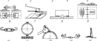
The first step in processing any material, be it wood, plastic or metal, is to apply visible guidelines for visual positioning or markers for automatic cutting. The simplest devices are known to everyone from school. These include rulers, bore gauges, compasses, squares, protractors, plumb levels, measuring rods, and center finders. The working line can be drawn with chalk, a felt-tip pen or scratched with a sharp object. When forming a straight line, pattern rules or a string are used. There are a huge variety of production techniques, and accordingly, there are no fewer ways to apply landmarks. We will try to briefly clarify what the main marking tools exist and when it is advisable to use them.
What are the names of auxiliary marking tools?
When making objects from wood or metal, you often have to draw various geometric shapes. The most common are rectangles and circles. To form such markings, many devices have been invented.
Squares
Everyone who has dealt with construction has always used a gadget that allows them to make a perpendicular. If on large surfaces it would be more correct to use the formula “3, 4, 5”, then it is convenient to mark small parts with a carpenter’s angle. The product has a supporting protruding edge and a ruler with dimensions from the stop and the outer point. In metalworking, along with similar models, more precise instruments are used. Despite their apparent simplicity, they make it possible to estimate the proximity of the edges to 90 degrees with very small errors. Even the storage of such nondescript “pieces of iron” is provided in a special pencil case to prevent precipitation and mechanical stress from getting on them.
Center finder - protractor
The rule of geometry, which states that the center of a circle to which an angle is applied will be located on the bisector, is the basis of this device.
To find the middle, use a square with two supporting surfaces and a rigidly set center line. The intersection of 2 marks gives the rotation point. Another task is to find the equidistant distance from the edge of the board. To do this, use a ruler with a central mark and two edge stops. By repainting the device, the desired middle is automatically found.
Malka
The device allows you to transfer the pattern angle to the workpiece, and also partially performs the function of a thickness planer. It is often combined with a protractor. The base has a supporting surface and a bar for applying marking points.
Erunok
After the right angle, the most commonly used angle is 45°. Therefore, the carpenter has always had and still has in his workshop a basic device for marking such lines. In essence, this is a small piece made at one angle.
Bore gauge
From time to time it becomes necessary to determine the diameter of a hole or the width of a groove. If the ruler and caliper do not allow you to transfer the size, then a special compass will be the solution. It is very similar to the regular one, but has touch points curved outward. In turning production, a digital high-precision analogue is used.
Folding meter
This device has almost replaced all kinds of roulettes in production today. But some craftsmen even today consider working with such a measuring object more convenient. Perhaps the main advantage is durability. The wooden analogue is also popular because it allows you to take measurements against a support.
Applying marks
The standard regulates the procedure for drawing marking lines:
- horizontal;
- vertical;
- inclined;
- curvilinear.
Applying curved elements after straight ones provides another opportunity to check their accuracy. The arcs must close the straight lines, the interface must be smooth.
Direct marks are carried out with a well-sharpened scriber, without tearing off, in one step. At the same time, the scriber is tilted away from the ruler or square so as not to introduce distortions.
Parallel lines are drawn using a square and moving it along the reference ruler to the required distance.
Applying mutually perpendicular and parallel marks
Applying marks at an angle to each other
If the workpiece already has holes, then a special tool, a center finder, is used to attach marking lines to them.
In order to mark inclined lines, use a marking protractor with a hinged ruler fixed at its zero point.
For particularly precise markings in plumbing, calipers are used. They allow you to measure distances and scratch marks with an accuracy of hundredths of a millimeter.
What tools are used as additional ones for marking, and what are they called?
There are an endless variety of processing technologies and models of final products. Therefore, non-standard solutions that are convenient for certain operations are often used. Both in metalworking and in the manufacture of goods from wood, plastic, stone, etc. The use of patterns became widespread. A line with a complex configuration is obtained by outlining a special pattern.
Before forming several radii, it is advisable to make an application point. This is done by punching. The device is somewhat reminiscent of a chisel, but with a sharp conical working surface made of hard alloy.
Marking and permanent marks are applied to metal using an electric engraver. This is essentially a micro welding machine. Due to the electric arc, a very clear local trace is formed. You can draw and write with it like a pencil.
What is markup
The operation of applying the dimensions and shape of a product to workpieces is called marking. The purpose of the operation is to designate the places where the part should be processed and the boundaries of these actions: drilling points, bend lines, weld lines, markings, etc.
Marks are scratched into the metal surface with a sharp tool or applied with a marker. Cores are filled with a special tool - a center punch.
According to the method of execution, there are such types of markup as:
- Manual. It is made by mechanics.
- Mechanized. Performed using mechanization and automation tools.
Based on the application surface, they are distinguished
- Superficial. It is applied to the surface of the workpiece in one plane and is not associated with the lines and marking points applied to other planes.
- Spatial. It is carried out in a unified three-dimensional coordinate system.
Notes on straightening and marking for thin sheet metal
The choice between surface and spatial markings is determined, first of all, by the complexity of the spatial configuration of the part.
Techniques
Markings, marking tools and fixtures are used in several different ways for a variety of tasks.
If woodworking allows you to use not only scratching scribers, but pencils, felt-tip pens, and even chalk, then when making elements from metals, it is preferable to apply marks with sharp instruments. This is due to the fact that precision is required within the limits of the thickness of the strip.
Welding work in most cases allows planning with a marker, since in the process of joining the workpieces the gap is filled with a seam.
§ 34. Marking parts made of metal sheet and wire
After editing, the contours of the future product are marked on the workpiece. Marking is carried out using marking tools: a scriber, a marking compass and a center punch using a metal ruler or square (Fig. 125).
Rice. 125. Marking tools: a - ruler; b - square; c - scribers; g - center punch; d - marking compass
The scriber is a sharpened metal rod and is used to apply marking lines (scores) to the workpiece.
Circles and arcs are drawn using a marking compass. The radius of a circle or arc is first plotted using a ruler.
By hitting the center punch with a hammer, holes are made on the surface to be marked, marking the centers of future holes.
When marking out parts according to a template, try to cut the material rationally, that is, so that the amount of waste is minimal.
This problem can be quickly and accurately solved on a computer. To do this, the part template and the metal sheet are drawn to scale. By moving and rotating the template, copying it repeatedly, you can achieve the optimal (best) arrangement of parts on the sheet.
Figure 126 shows a drawing of the “eyelet” part, made of thin steel sheet and used for hanging wall panels. The value S 0.8 in the drawing means that the sheet thickness is 0.8 mm.
Rice. 126. Drawing of the “eye” part
Marking begins with drawing contour lines of the part and lines of symmetry with a scriber, then drawing the center lines of holes and arcs, drawing circles and arcs with a compass. Finish the marking by marking the centers of the holes.
A development is a flat image of a part blank (for example, a box), which becomes three-dimensional when bent. The reamer is marked according to the drawing, and then a flat part blank is cut out.
The layout is marked using a ruler and a metal square, starting from the base (largest) sides, then the other sides are measured and outlined, and center lines and fold lines are drawn.
Practical work No. 36 Marking parts made of metal sheet and wire
Work order
- Prepare your workplace, tools and workpieces for marking.
- Mark blanks for making parts and products from thin metal sheet and wire (preferably for your creative project).
- Check the markings are correct.
Control questions
- What is marking called and why is it done?
- What tools are used for marking?
- How to mark products made of metal sheet and wire?
- What is called a sweep?
- In what sequence are the scans marked?
What tools should be used when marking circles and devices for this process
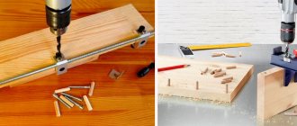
Forming a pattern in the form of a circle is done with a compass. This works well for parts ranging in size from a few centimeters to a meter. Small holes are easier to apply using a pattern. Large radii will have to be created by creating a special analogue. In many cases it is necessary to make the center with a core or drill. If damage is unacceptable, then use a suction cup, for example, when cutting glass.
In mass production, it would be most correct to use a template made for a specific workpiece. Here, not only evenness is taken into account, but also the positioning of the lines relative to each other.
It is often necessary to draw an oval (ellipse). In this case, a cord is taken, two centers are fixed and a sharp object is drawn around two points. The sum of the distances between the three source data is always constant. This is achieved by using a measured section of cord.
In our article we wrote about which tools are marking tools, their purpose and structure. Marking is a very responsible task. The accuracy of the product ultimately depends on it. The most suitable devices are selected for each technological method. Progress does not stand still; more and more new unusual gadgets are hitting the market. In order not to get lost in this diversity, we advise you to consult with specialists from competent companies, for example, Rosta LLC. Managers will select the most suitable option for you and tell you how to use it. To reinforce the material, watch two videos:
§ 34. Marking parts made of metal sheet and wire
After editing, the contours of the future product are marked on the workpiece. Marking is carried out using marking tools: a scriber, a marking compass and a center punch using a metal ruler or square (Fig. 125).
Rice. 125. Marking tools: a - ruler; b - square; c - scribers; g - center punch; d - marking compass
The scriber is a sharpened metal rod and is used to apply marking lines (scores) to the workpiece.
Circles and arcs are drawn using a marking compass. The radius of a circle or arc is first plotted using a ruler.
By hitting the center punch with a hammer, holes are made on the surface to be marked, marking the centers of future holes.
When marking out parts according to a template, try to cut the material rationally, that is, so that the amount of waste is minimal.
This problem can be quickly and accurately solved on a computer. To do this, the part template and the metal sheet are drawn to scale. By moving and rotating the template, copying it repeatedly, you can achieve the optimal (best) arrangement of parts on the sheet.
Figure 126 shows a drawing of the “eyelet” part, made of thin steel sheet and used for hanging wall panels. The value S 0.8 in the drawing means that the sheet thickness is 0.8 mm.
Rice. 126. Drawing of the “eye” part
Marking begins with drawing contour lines of the part and lines of symmetry with a scriber, then drawing the center lines of holes and arcs, drawing circles and arcs with a compass. Finish the marking by marking the centers of the holes.
A development is a flat image of a part blank (for example, a box), which becomes three-dimensional when bent. The reamer is marked according to the drawing, and then a flat part blank is cut out.
The layout is marked using a ruler and a metal square, starting from the base (largest) sides, then the other sides are measured and outlined, and center lines and fold lines are drawn.
Practical work No. 36 Marking parts made of metal sheet and wire
Work order
- Prepare your workplace, tools and workpieces for marking.
- Mark blanks for making parts and products from thin metal sheet and wire (preferably for your creative project).
- Check the markings are correct.
Control questions
- What is marking called and why is it done?
- What tools are used for marking?
- How to mark products made of metal sheet and wire?
- What is called a sweep?
- In what sequence are the scans marked?
Measuring tool
In technology, such a concept as measurement means a certain set of actions, the result of which is the determination of the numerical value that a certain physical quantity of an object has. Measurements are made using special technical means experimentally.
In an industry such as mechanical engineering, it is absolutely impossible to do without carrying out various measurements . The quality of the products directly depends on the precision with which they are carried out. As for measurement accuracy , at modern machine-building enterprises it is usually in the range from 0.001 millimeter to 0.1 millimeter.
In order to quickly and with minimal errors make technical measurements , specialized instruments and designs are used.
Dial indicator
This measuring instrument is a device where very small movements made by the measuring probe are converted into angular movements of the arrow. Dial indicators are used when it is necessary to determine with a significant degree of accuracy those deviations that a certain part has in its geometric shape in relation to the specified parameters. In addition, these devices are used to control the relative position of surfaces.
Shtangenreysmas
This measuring tool is designed to measure the heights of parts and accurately mark them. The maximum measurement limit of height gauges is 2500 millimeters, and the division price of their verniers is 0.1 or 0.05 millimeters.
In most cases, this measuring tool is used when working on special cast iron plates. It is on them that it is installed along with those parts that need to be measured or marked.
In order to draw a line on the part to be marked using a height gauge, a special replaceable leg is used. The measuring tool itself moves directly along the surface of the slab.