Design and operation of composite crank sheet shears N3121
- bed
- Drive unit
- Knife beam
- Clamp
- Rear stop
- Drive shafts
- Clutch
- Balancer
- Electromagnetic control
- Brake
- Fencing
- Protective grille
- Electrical equipment
- Remote Control
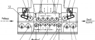
The shears are driven by electric motor 1. Pulley 2, sitting on the electric motor shaft, uses a V-belt drive 3 to rotate flywheel 4. Flywheel 4 is mounted on drive shaft I. At the other end of shaft I, an inertial flywheel 10 is mounted. A gear is mounted on shaft I 5, which is in mesh with a gear 6, which is fixed to the intermediate shaft II. Gear 7 is mounted on the other end of shaft II and is in mesh with gear 8, inside of which the engagement clutch 9 with rotary keys is mounted. The clutch is turned on and off by an electromagnet 11, a system of levers 12 and springs located on the clutch cover. When the electromagnet is turned on, the clutch transmits rotational motion to the eccentric shaft III, which, through connecting rods 13, causes the knife beam 14 to reciprocate. When the knife beam moves downward, the clamping beam 17 presses the sheet being cut to the table at the moment of cutting. The movement of the clamp is associated with the movement of the knife beam. To reduce dynamic loads, knife beam balancers 15 are provided. The rise of the clamp 17 occurs when the knife beam is lifted, when the stops 18 installed on it pull the clamp upward.
To stop the knife beam 14 in the uppermost position, a brake 19 is used, installed at the right end of shaft III.
Description of the components of crank sheet shears N3121
Scissor bed N3121
All mechanisms and components of crank sheet scissors N3121 are mounted on the frame.
The frame is a welded structure consisting of two racks connected to each other by ties and a table. The table is attached to the stands with bolts. The lower knives are attached to the table with screws. A slide is provided to remove cut workpieces.
Crank sheet shear drive N3121
The electric motor of the scissors is hinged on the bed plate. The tension of the V-belts is adjusted by changing the angle of inclination of the electric motor using a tension screw.
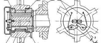
Clutch for engaging crank shears H3121
The design of the engagement coupling with rotary keys is shown in the figure.
The engagement clutch is rigidly attached to the wheel hub 12 using bushing 2. When the electromagnet is turned off, bushing 2 rotates freely with wheel 12 without engaging with bushing 7, which is wedged relative to shaft 14 and key 13. Bushings 8 and 9 are plain bearings.
When the electromagnet is turned on, the shank 4, located at the right end of the key 10, is released from the stop of the electromagnet, and the springs 6 actuate the levers 5. The levers 5 rotate the working 10 and locking key 11 of the engagement clutch, and they occupy a working position, entering the grooves of the bushings 7 and 2, rigidly connect them to each other. From wheel 12 through bushings 1, 2, 3, rotation is transmitted to bushing 7, from it through key 13, rotation is transmitted to shaft 14. The shaft makes one revolution (working stroke), the shank rests on the pin, turning the working key 10 and, at the same time, through levers 5 locking key 11, the clutch is disconnected.
In idle mode, the gear rotates freely on a pair of plain bearings 8 and 9.
Knife beam of crank shears H3121
The knife beam is an L-shaped welded structure, reinforced with stiffeners. The cutting knives are attached to the beam with screws.
Clamp and protective grid of crank shears H3121
While the scissors are working, the sheet being cut is pressed against the table by a pressure beam. As the cutter beam moves downwards, the clamping beam clamps the sheet, and then the cut begins. The lifting of the clamp is carried out by the stops of the knife beam, resting against the clamping plates.
The clamping force is adjusted using nuts that compress the spring of the clamping beam.
A protective grille is rigidly attached to the guide bars of the clamp, protecting the worker’s hands from falling under the clamp. When the protective grill is removed, the electrical interlock is activated and the scissors are automatically switched off.
Rear scissor stop N3121
The installation is equipped with a back stop for cutting sheets of a given size. The back stop consists of a stop ruler and two cylindrical slats that are moved manually. When cutting a sheet longer than 500 mm, the stop corner is removed.
Crank shear balancers H3121
Balancers serve to compensate for the weight of the cutter beam, reducing dynamic loads when working with scissors.
The balancer consists of two sets of springs installed in cups welded to the channel box of the frame.
The balancer rods are pivotally connected to the knife beam.
Scissor guards H3121
The shear guards have a welded design and are made of thin sheet steel. Consists of four casings that cover the motor pulley, flywheel, V-belt gear and gears. All fences are attached to the frame with bolts.
Kinematic diagram of crank shears N3121
| Installation model | Number of teeth/module | Electric motor power, kW | |||
| Z1/m1 | Z2/m2 | Z3/m3 | Z4/m4 | ||
| H3121 | 19/10 | 52/10 | 19/12 | 75/12 | 37 |
Main performance characteristics
When purchasing scissors, you should pay attention to the passport, which contains basic information. As a rule, the passport contains the following information:
- the maximum thickness of the metal being cut is 12.5 millimeters;
- maximum sheet length 2,000 millimeters;
- the minimum number of knife strokes in automatic mode in one minute is 40 times;
- the width of the sheet at a given stop is 500 millimeters;
- maximum force 50,000 kgf;
- the power of the installed electric motor is 18.5 kW;
- clamping force – maximum value 2,900 kg;
- type of installed brake – band;
- equipment weight is 7,000 kilograms.
The above information is indicated in the passport. The passport may also indicate a kinematic diagram that is used during repair work.
Preparation of crank shears N3121 for work and operating procedure
The requirements set out below are mandatory when starting up the shears after installation, as well as after repairs or a long break in operation.
- Ground the H3121 scissors, connect it to the electrical network, checking the compliance of the network voltage and the electrical equipment of the scissors.
- Follow the instructions in the Lubrication section.
- Check the tightness of all bolts and their locking.
- Turn on the introductory machine. In this case, the “Voltage applied” signal lamp should light up. If the signal lamp does not light up, it is necessary to check the voltage in the network in accordance with the technical operation rules, because the absence of a signal does not yet indicate a lack of voltage.
- Turn on the drive electric motor by pressing the “Start” button and accelerate the flywheel. Check the direction of rotation of the large gear sitting at the end of the eccentric shaft on the clutch side. The gear should rotate clockwise when viewed from the clutch side. Reverse rotation is not allowed.
- Run the N3121 scissors for two hours, of which one hour on single strokes and one hour on automatic ones. At the same time, check the interaction of all components and parts of the scissors.
Purpose and scope
H3121 guillotine shears are used for cutting when the cross-sectional thickness is more than 6.3 millimeters. In this case, the density of the material being processed should not exceed 150 kg/m2, since otherwise the created force will not be enough.
The main area of application of the N series guillotine is workshops and warehouses of various enterprises where metal cutting work is carried out. Model H3121 is in demand:
- at machine-building, automobile-building, and shipbuilding enterprises, where sheet metal blanks are used to create hulls and other structural elements;
- at procurement sites, where sheet material arrives, is cut and sent to the production workshop.
Download the passport of guillotine shears H3121
High productivity and relative compactness determine that H series guillotines are used in large-scale production with the installation of a conveyor feed of workpieces. Quick setup from the operator's station allows you to reduce equipment downtime due to the receipt of workpieces of different thicknesses or lengths.
Operating procedure for crank sheet shears H3121
Before starting work, you must meet the following requirements:
- Lubricate the scissors
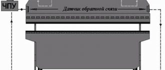
- Adjust the back stop to the required cutting length of the workpiece. The distance from the cutting edges of the lower knife to the back stop is determined by rulers mounted on the back stop slats.
- Set the required gap between the upper and lower knives. To do this, it is necessary to loosen the bolts pos. 1 and pos. 3, Figure 5, which secure the table to the frame. By manually rotating the flywheel according to the arrow indicated on the casing, lower the knife beam down until the table knives and knife beam overlap (10 mm - overlap of the knives).
- Move the table forward and set the required gap, then, lowering the knife beam down, measure the gap along the entire length of the knives from left to right. After setting the gap, tighten the bolts. The table moves backward relative to the knife beam using bolts in position 2, Figure 5. The gaps between the guides and the knife beam are secured with spacers, position 4, Figure 5.
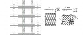
The gap size is set according to the table
| Thickness of the sheet being cut, mm | 5-6 | 7-8 | 9-12 | 12-16 | 17-20 |
| Gap size, mm | 0,3 | 0,4 | 0,5 | 0,6 | 0,7 |
- Engage the clutch at maximum flywheel speed.
- Make several idle strokes, make sure that the scissors are working properly
During operation:
- Do not allow unauthorized persons to access the scissors.
- DO NOT ALLOW CUTTING SHEET OF MAXIMUM THICKNESS WITH A STRENGTH LIMIT MORE THAN 500 MPa The maximum thickness of a sheet with a tensile strength more than 500 MPa is determined by the formula: δх = δ x 500/σх mm. where δх is the maximum permissible thickness of a sheet with a tensile strength more than 500 MPa σх is the limit strength of the sheet being cut, MPa.
- DO NOT CUTTING SHEET WITH DULL KNIVES. The knives are made with four cutting edges; when the cutting edges become dull, the knives are periodically turned over. Dull knives must be ground.
- When cutting workpieces longer than 800 mm, to avoid sheet shrinkage, use supports to support the workpiece being cut.
- If there is no electricity, turn off the input circuit breaker in the electrical cabinet
Upon completion of work:
- Stop the shear drive.
- Turn off the input circuit breaker.
- Clean the scissors and lubricate it.
- Notify your replacement about any problems you notice.
Maintenance of crank shears H3121
The scissors maintenance system determines the order, content and frequency of inspection and maintenance of scissors during operation.
The following types of maintenance are provided:
TO – 1 – daily;
Maintenance – 2 – every three months;
Maintenance – 3 – annual.
The work provided for by TO - 1 - TO - 3 covers the inspection and maintenance of the main mechanisms that determine the reliability of the scissors.
STRICT COMPLETION OF THESE WORKS IS MANDATORY
Typical malfunctions of crank shears H3121 and methods for their elimination
The sliding bearings of the connecting rods and axle boxes get hot, and there are bronze particles in the lubricant
| Small gap between shaft journals and liners | Scrub the liner |
| No lubrication | Check lubricant supply |
Tight sliding of the knife beam
| Gasket wear | Replace gaskets |
| No lubrication | Check lubricant supply |
In single stroke mode, the blade bar does not stop at the top point
| Worn brake band | Change feed |
| Spring is loose | Tighten the spring |
| Oil got on the brake drum | Remove grease from the brake working surface |
| Wear of clutch parts | Replace worn parts |
| Electromagnetic control is out of adjustment | Adjust electromagnetic control |
| Wear of electromagnetic control parts | Replace worn parts |
| Clutch does not engage | Adjust the clutch |
When you press the buttons or pedal, the scissors do not turn on
| There is a problem with the electrical circuit. | Clean the contacts, check the serviceability of the starters, check the serviceability of the fuses |
The electric motor does not develop full speed when starting
| Break in the supply circuit | Check according to the diagram and fix |
| Problem with starting equipment | Check according to the diagram and fix |
Purpose and areas of application
Scope of application – industrial, procurement shops of small-scale, medium-scale production. As a rule, sheet materials are used in the manufacture of body parts. That is why guillotine shears model H3118 can be found in the field of machine building, shipbuilding, and in procurement shops.
Purpose – cutting sheet materials to specified sizes. Processing is carried out exclusively in the transverse, longitudinal and straight directions along the thickness of the sheet. However, there are certain restrictions on how thick the sheet can be. The sheet should not be higher than 50 kgf/mm 2.
It is the technical characteristics that determine the possibility of using model H3118 scissors in certain situations. The technical characteristics of the H3118 guillotine include:
- maximum metal thickness 6.3 millimeters;
- maximum length of sheet material 2,000 millimeters;
- knife stroke frequency when selecting automatic processing (minimum value) 21 strokes per minute;
- maximum sheet size at a given stop is 630 millimeters;
- the force exerted by the pressure beam is 25 kN;
- the height of the structure above the floor level is 1945 millimeters;
- the maximum deviation for given dimensions when cutting a workpiece length of 1,000 millimeters is 0.25 millimeters;
- control can be carried out using a remote control with buttons or pedals;
- the move can be continuous or single.
The above characteristics determine the features of the model of sheet metal cutting machine under consideration.
Download the passport of guillotine shears H3118
Download drawings of wear parts N-3118
Installation procedure for crank sheet shears H3121
- Crank sheet shears N3121 are delivered to the customer assembled.
- Unpacked scissors should be lifted using the holes in the frame, according to the slinging diagram
- The installation drawing of the scissors is shown in The foundation depth H is taken depending on the nature of the soil, but not less than 800 mm.
- The horizontal position of the scissors on the foundation is made using wedges and checked by a level installed on the scissors table. The installation accuracy in the transverse and longitudinal directions must be at least 0.2 mm. At a length of 1000 mm.
- After installing the scissors on the foundation, it is necessary to carry out re-preservation. Removal of the anti-corrosion coating is carried out with a wooden spatula and a rag moistened with gasoline B-70 GOST 51-82
- To avoid corrosion, cover the unpreserved treated surfaces with a thin layer of Industrialnoe 80 oil GOST 20799-88.
Slinging diagram for scissors H3121
Installation drawing of crank shears H3121
H3121 Guillotine crank shears for sheet metal
The Shimanovsky Forging and Pressing Equipment Plant, together with the Lvov Diamond Tool Plant, launched the production of N series guillotines, which began to be widely used when it was necessary to process sheet material. H series guillotines are crank shears that cut various metals and are designed for longitudinal and linear changes in sheet dimensions. Sheet blanks can be processed according to pre-applied markings or installed stops: rear and side. The characteristics of the H3121 determine the possibility of using the equipment in medium and large-scale production.
Electrical equipment of scissors N3121
- Type of current – alternating, 3-phase.
- Voltage – 380; 50 Hz.
- Control voltage:
- — alternating current – 110V; 50 Hz;
- Signaling circuit voltage – 24V; 50 Hz.
- Lighting circuit voltage – 24V; 50 Hz.
- The list of pantographs and devices is given in Table 6.
- On the front side of the scissors there are: limit switch – grid lock; control panel (shown in Figure 9).
- The control cabinet is installed on the left post of the frame. On the right wall of the cabinet there are: an operating mode switch and a pedal. An input machine is installed on the left wall of the cabinet.
| Pos. Designation | Name |
| QF FU1,FU2 FU3,FU4 | Automatic machine AE2046MP 1n=63A, ots=12, 660V with mounting behind the TU16-522.139-78 panel Automatic switch VA47-29, 16A Automatic switch VA47-29, 10A, 6A |
| HL1 HL2 HL3 - HL5 | Light indicator AD-22DS, 24V (red) AD-22DS, 24V (red) AD-22DS, 24V (green) |
| KM1,KM2 | Magnetic starter PML-1100, 10A, 110V |
| K.M. | Magnetic starter PML-4100, 63A, 380V |
| M | Engine AIR160 M4 U3, 18.5 kW, 1500 rpm, 380 V 50 Hz, GOST 28330-96 |
| S.A. | Switch PKU3-11 4028 U2 |
| S.Q. | Limit switch VPK 2112 BU2 |
| SB1 SB3 SB4,SB2 | Switch TU 3428-002-05758144-95 VK43-21 11110 1z+1r – red VK43-21 11110 1z+1r – red VK43-21 11110 1z+1r – black |
| YA | Electromagnet ED10102U3 Armature stroke 40 mm. 380V, 50Hz TU16-529.161-79E |
| T | Transformer OSM1-0.16U3 220/110-22-5/24 |
| SM2 | Switch ALC-22 |
| SB5 | Button KE-011U3, version 2 |
The electrical circuit of the N3121 scissors provides the following modes:
- disabled;
- manual control;
- pedal control;
- automatic cycle.
The selection of modes is carried out by the SA switch installed on the right wall of the cabinet.
Symbols of control elements of scissors H3121
Manual control
The mode switch SA is set to the “Manual control” position, when the SB4 button is pressed, a single cycle occurs: the KM1 relay turns on, and the YA electromagnet turns on, which turns on the clutch.
Pedal control
The SA mode switch is placed in the “Pedal control” position, and when the SB5 pedal is pressed, a single cycle occurs.
Automatic cycle
The mode switch SA is set to the “Automatic cycle” position, and when the SB4 button is pressed, KM1 is turned on and becomes self-powered, the electromagnet YA is constantly on, continuous strokes (cycles) of the knife beam occur. Disabling is done with the SB3 button.
Protection and blocking
The circuit is protected by automatic switches. Thermal protection of the motor is carried out by a thermal relay. The electrical circuit provides for blocking - the scissors cannot operate if the grille is removed, that is, the SQ limit switch must be pressed.
Signaling and local lighting
The electrical circuit provides the following alarm:
- presence of voltage HL1;
- engine on HL2;
- automatic cycles HL3;
- single loops HL4;
- HL5 pedal.
A local lighting lamp is provided to illuminate the cutting line.
Electrical circuit diagram of guillotine shears H3121
Electrical diagram of guillotine shears N3121
The circuit is designed to control a machine with a rigid coupling to clearly engage and disengage the moving slide with the tool. The clutch is activated by an electromagnet, which is activated by an intermediate relay.
Complete shutdown of the circuit is carried out by the input circuit breaker.
Electrical equipment of scissors N3121
The machine is controlled from the control panel. on which control buttons and mode switches are located
The alarm system is electric and light; the designation of modes and controls is symbolic.
- automatic (continuous running);
- single move.
- buttons;
- pedal only on single strokes.
The electrical circuit includes the following circuits:
- A. AC power circuit, voltage 380 V.
- b. AC control circuit, voltage 36 V.
- V. AC lighting circuit, voltage 5.5 V.
The following receive power from the power circuit:
- A. Main drive electric motor.
- b. Pulling electromagnet.
- V. The control, lighting and alarm circuits receive power from the secondary windings of the 2T transformer.
Control and protection equipment (transformer, magnetic starters, circuit breaker) are located in the electrical cabinet.
The operation of the scissors is controlled from the control panel.
Description of the operation of the electrical circuit
The electrical circuit provides the ability to operate the scissors in the following modes: “Single stroke”; "Automatic moves."
The selection of the operating mode is carried out by readjusting the scissors (by adjusting the electromagnet thrust) and setting the operating mode switches PR and PU to the desired position, located in the lockable control panel. When resetting the PR and PU switches, the electric motor must be turned off with the 2KU button.
Single move mode
In this mode, operation with a button and a pedal is possible. The PR switch is set to the “Single stroke” position. The thrust of the electromagnet is mechanically adjusted.
a) Button Control
The PU switch is set to the “Button” position. When you press the “Drive Start” button (2KU) along the circuit 1-9-7-15-19-23-3-2, the magnetic starter 1K is turned on, which turns on the main drive electric motor (1D).
Through the normally closed contacts of the 4KU button and the 2K magnetic starter, the 1RP relay receives power via circuit 19-17-115-21-2, becomes self-powered, and with its normally open contacts (circuit 25-31) prepares the 2K magnetic starter, which turns on the electromagnet, for switching on. When you press the 4KU button, the 2K starter is turned on, and therefore the electromagnet E. The 2K starter, turning on, breaks the circuit 21-115 with its normally closed contact,
1 PR turns off and turns off with its no. O. contact circuit 25-31. This turns off the electromagnet E., i.e., electrical blocking from doubling of strokes.
b) Pedal control
The PU mode switch is set to the “Pedal control” position. When you press the “Drive Start” button (2KU), it turns on the electric motor of the main drive 1D.
When you press the pedal, the 2K magnetic starter and electromagnet E are turned on.
Electrical blocking against doubling of strokes is carried out in the same way as when operating buttons.
Automatic mode
The electromagnet thrust for automatic strokes is mechanically adjusted. The PR operating mode switch is set to the “Automatic” position, and the PU switch is set to the “Buttons” position.
When you press 4KU, the 2K magnetic starter is triggered and turns off the electromagnet. Starter 2K with its own no. O. contacts 25-105 become self-powered, automatic movements occur until the 3KU button is pressed.
Locking and alarm
Locking, which ensures complete voltage relief from all equipment when opening the electrical cabinet door, is achieved by turning off the 1A circuit breaker.
The interlock, which ensures that the control circuit is turned off, is achieved by the 1VK limit switch located in the electrical cabinet, which turns off the control circuit when the door is opened.
The blocking, which excludes the possibility of obtaining moves when the protective grille is raised, is carried out by the 2VK end.
The blocking, which prevents the clutch from engaging when operating on “Single and automatic strokes” without turning on the main drive, is achieved by contact 1K (circuit 15-19).
The electrical circuit provides an alarm indicating the presence of voltage in the control circuit. When voltage is applied, a white 1LS lamp on the control panel lights up.
When the main drive motor is turned on, green lamp 2 lights up on the control panel (engine is on).
Protection
Protection of the electrical equipment of the scissors from short circuit currents is carried out by a 1A circuit breaker and fuses 2P, 3P, 4P.
Thermal protection of the main drive motor is carried out by a thermal relay RT, built into 1K magnetic starters.
Zero protection of the electrical circuit is provided by magnetic starters 1K, 2K.
Safety precautions
The electrical equipment of the shears must be reliably grounded in accordance with the current “Rules for Electrical Installations” by connecting the shear frame and electrical cabinet to the workshop grounded circuit.
Before starting work, inspect the scissors and check the grounding.
In order to increase the safety of operating personnel, the electrical circuit provides for locking:
- electrical cabinet doors;
- control panel doors.
During long breaks in scissor work or after the end of the shift, the input circuit breaker is turned off.
The first switching on of the circuit breaker should be carried out briefly, followed by inspection and verification of the correctness of the light signals.
The control panel has a red mushroom-shaped “General Stop” button (1KU) to completely disable the circuit.
It is strictly forbidden to work with scissors if the locks are faulty.
The installation of PU and PR switches is carried out by an adjuster.
Access to the electrical cabinet is permitted only to electrical personnel assigned to the machine.
Security measures
- Safety of work on N3121 scissors is ensured by the installation of protective covers on all rotating parts, the presence of a protective grille equipped with an additional electrical lock that stops the scissors when the protective grille is removed. The electrical cabinet is equipped with special locks that prevent access to it by unauthorized persons.
- When changing knives and repairing scissors, the knife beam should be fixed in the upper position with pins with a diameter of 25 mm inserted into special technological holes in the knife beam.
- During operation of the scissors, it is necessary to ensure that the knife beam remains in its highest position, which
- achieved by correct brake adjustment.
IT IS STRICTLY PROHIBITED:
- Allow persons who do not have the necessary qualifications and have not undergone safety training to work with scissors.
- Working with faulty scissors.
- Work with scissors with the guards and protective grilles removed.
- Carry out repair and adjustment work, as well as cleaning and lubricating the shears with the electric motor running.