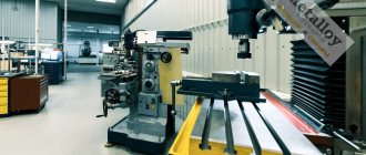
CNC press brakes are designed for cold deformation of thin sheet metal. Due to automation, high bending accuracy is ensured, productivity increases compared to conventional machines, and the creation of structures with different geometries is simplified. Designed for serial production of parts.
CNC Press Brake
What is a CNC Press Brake
CNC sheet bending is high-performance pneumatic equipment designed for processing workpieces made of various metals. Allows you to bend thin sheets evenly and give them the desired shape. The presence of a CNC ensures process automation, more accurately controls mechanisms, and monitors the current state and sensor readings.
Unlike conventional mechanical analogues, such machines minimize the likelihood of creating defective parts. Punches and dies are easily replaced without the use of physical force.
Design and operating principle
The mechanical part of the press consists of the following components:
- the bed, which ensures the stability of the machine and keeps it from swinging;
- tools for bending workpieces;
- servomotors that drive equipment;
- hydraulic drives;
- guides for moving the working tool.
The design also provides protection for the operator from injury:
- electronic sensors that determine machine operating parameters in real time;
- steel shield to prevent contact of the workpiece with the operator during press operation;
- electronic regulation of the position of the part on the work table;
- indicator that allows you to control the bending process.
Changes are made to the computer program of CNC machines based on the dimensions of the working tool, and readjustment is performed. It is enough to perform the setup once, and in the future you only need to download the necessary programs. The number of recorded programs depends on the memory capacity.
Beds in equipment are of the following types:
- C-shaped. Used to accommodate various equipment and press maintenance. It has a wide working area, behind which there is a pocket. The structure cannot withstand overloads (deforms).
- O-shaped. It is characterized by high strength and resistance to overloads. Finished parts are difficult to obtain. It is not possible to install auxiliary equipment on it.
The bending force depends on the strength and thickness of the metal. For aluminum, the optimal force is considered to be from 30 to 60 MPa, for low-carbon steels - from 75 to 110 MPa, for brass - from 70 to 100 MPa. Typically, up to 30% is added to the calculated press load values to increase efficiency.
The operating principle is as follows:
- A traverse is attached to the upper part of the press.
- When the program is executed, the traverse moves along vertical axes at a given speed to bend a specific metal of a certain thickness.
- When approaching the workpiece, the speed of movement of the traverse increases to working speed using hydraulics. The CNC controls the sensor parameters and is responsible for the entire bending process.
- Upon reaching the bottom point, the traverse stops and remains in this position for some time. The duration of compression allows you to give the final shape to the workpiece.
- The decompression stage begins: the traverse moves upward after pressing. The speed is determined by the technological process.
- After decompression, the speed of movement of the press increases until the top point is reached.
- To remove the workpiece, the equipment is turned off. On automated lines, the part is removed automatically, and then a new workpiece is loaded.
CNC sheet bending machine
Types of equipment
Presses for free bending of sheet metal have a similar design and the same layout of the main components and assemblies. A typical representative of such equipment consists of the following components:
1. Portal-shaped frame made of thick sheet metal. It consists of a support base and two wide C-shaped posts with side openings, connected at the top by a fixed cross member.
2. Lower bending beam (work table) - a long and narrow box-shaped structure mounted on the bottom of the racks. A matrix is attached to its end.
3. Slider (moving beam, traverse). Similar in design to the bottom beam. It moves along guides located at the ends of the machine stands. A punch is attached to the lower surface of the slide.
4. Drive. Located on the top of the bed. Transmits controlled movement to the slider.
5. Back stop. Located behind the bottom beam and used for precise positioning of sheet metal before bending begins. In its simplest form, it is made in the form of a movable bar parallel to the matrix.
In addition to sheet benders with an upper slider, there are machines in which the slider is stationary, and the sheet bending beam with a matrix and stops moves from bottom to top. In this case, the drive is located at the bottom, which increases the stability of the machine, but there is an inconvenience in that the workpiece and adjustable stops rise upward.
There are several types of drives used on sheet bending equipment. Pneumatic slider moving devices are now used very rarely and only on low-power machines. The most common crank mechanism in the recent past has now been almost completely replaced by a drive using hydraulic power cylinders, which is currently the most widely used in all types of sheet bending machines. And the most promising in terms of accuracy, efficiency and ease of CNC control is the electromechanical drive, implemented on a ball screw. But such solutions have not yet become widespread due to the high cost and complexity of implementation on large-sized equipment.
One of the key components of any press brake is a system for compensating for the deformation of both beams of the machine, which affects the accuracy and shape of the bend. Among the manual methods, the most common is leveling the beam using wedges. In addition, there are CNC-controlled compensation systems. In this case, dual power hydraulic cylinders and mechanisms with pulleys are used for the slider, and special hydraulic and electromechanical devices are used for the lower beam.
Criterias of choice
The choice of a press brake model is determined by the tasks for which it will be used, and is made on the basis of technological, production, operational and economic criteria. The first of them are based on the design features, dimensions and material thickness of the parts to be manufactured on this equipment. Based on these indicators, first of all, the dimensions of the processing zone of the bending machine are determined, which consist of the following technological characteristics:
- length of the bottom beam of the bending machine;
- distance between posts;
- slider lift height;
- distance from the bottom edge of the punch to the table;
- pharynx depth;
- maximum travel of the back stop along the Z axis.
Another defining technical parameter is the nominal pressing force of the sheet bending machine. The thickness of the processed material, the quality of processing and the productivity of the press depend on its size.
Production criteria are developed based on the intended method of loading equipment (single or batch production), as well as the time requirements for the sheet metal processing process. The latter include the norms of preparatory and final, auxiliary and main time, the minimization of which is achieved through mechanization and the use of CNC. These production indicators are directly affected by the speed of the following operations:
- feeding the workpiece and removing the part from the processing zone;
- technological adjustment of the lower beam and slider;
- replacement of sheet bending tools;
- adjusting the back stop;
- moving the part in the processing area;
- inlet, outlet and working stroke of the slider.
The economic criteria for choosing a sheet bending machine are primarily based on the standard payback period for the equipment. Here, the main factors, in addition to the price of the machine itself, include the cost of its delivery, installation, commissioning and personnel training, as well as operating and production costs. Operational criteria typically relate to the production space required for the press, power supply, and maintenance.
Specifications
CNC sheet bending machines have the following parameters:
- working surface length - from 1 to 6 m;
- press force - 400–4000 kN;
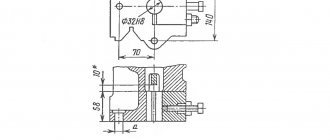
- the maximum thickness of the workpiece with a material strength of 70 kgf/mm2 is up to 10 mm;
- vertical idle speed up to 120 mm/s, working speed - up to 12.9 mm/s, reverse speed - up to 130 mm/s;
- distance between racks - from 1 to 5.1 m;
- power of installed engines - up to 18.5 kW;
- table height - from 0.8 to 1.1 m;
- the total weight of the machine is from 2.6 to 300 tons.
Why Leadermash?
- representative of the LZK company in Russia, exclusive supplier. We always meet our customers halfway, offering the best conditions for a profitable purchase. We are sure that there is a way out in any situation, so we find simple, effective solutions. With us you can get a loan, leasing, or buy new equipment through the Trade-in program.
They employ professionals who know everything about the equipment they sell.
You can order additional services from us - engineering, production audit, commissioning and installation work. We deliver CNC sheet bending machines at carrier rates, without additional extra charges. All details on prices and characteristics of equipment can be clarified with the manager by phone. Expand
Varieties
According to the types of press mechanisms for bending sheets, there are the following types:
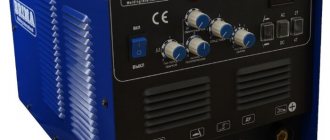
- hydraulic sheet bending machine - hydraulic drives are used to create force on the press;
- pneumatic - compressors are used to pump air under pressure into special pneumatic cylinders;
- electromagnetic - works on the principle of creating an electromagnetic field between the working surface and the press;
- manual - the operator uses his own strength to bend sheets;
- electromechanical - energy is transferred to the press through the operation of an electric motor and belt or chain drives.
By installation method;
- stationary;
- mobile.
According to the method of installing the workpiece inside the press:
- automatic;
- manual.
According to the principle or method of bending metal sheets:
- rotary with 2–4 shafts - the workpiece is deformed during the rolling process;
- rotary-bending - the sheet is fixed on the working surface and then deformed from bottom to top by a pressure beam;
- vertical bending - works on the principle of exerting pressure on the workpiece with a vertically moved punch; dies, press dies, and cotter pins are installed on the machines.
I. Which bending method should I choose?
There are 2 main bending methods.
We speak of "air bending" or "free bending" if there is an air gap between the sheet and the walls of the V-die. This is currently the most common method.
If the sheet is pressed completely against the walls of the V-shaped die, we call this method "sizing". Despite the fact that this method is quite old, it is used and even should be used in certain cases, which we will consider below.
Free bending
Provides flexibility, but has some limitations in accuracy.
Main features
The traverse, using a punch, presses the sheet to the selected depth along the Y axis into the groove of the matrix. The sheet remains “in the air” and does not come into contact with the walls of the matrix. This means that the bending angle is determined by the position of the Y axis and not by the geometry of the bending tool.
The Y-axis adjustment accuracy on modern presses is 0.01 mm. What bending angle corresponds to a certain Y-axis position? It's hard to say because you have to find the correct Y-axis position for each angle. The difference in the position of the Y axis can be caused by the adjustment of the lowering stroke of the traverse, the condition of the bending tool and the properties of the material: thickness, tensile strength, strain hardening.
The table below shows the deviation of the bending angle from 90° at various Y-axis deviations.
Advantages of free bending
- High flexibility: without changing bending tools, any bending angle between the V-die opening angle and 180° can be achieved. For example, 86° or 28°.
- Lower tool costs.
- Less bending force compared to calibration.
- You can “play” with force: a larger opening of the matrix means less bending force. If you double the width of the groove, you only need half the force. This means you can bend thicker material at a larger opening with the same amount of force.
- Less investment as a press with less force is needed.
But this is just a theory. In practice, you can save money by purchasing a lower-pressure press that takes full advantage of air bending and spend it on additional equipment. For example, on additional backgauge axes or manipulators.
Disadvantages of Air Bending
- Less precise bending angles for thin material.
- Differences in material quality affect repeatability.
- Not applicable for specific bending operations.
Our advice
- It is advisable to use air bending for sheets with a thickness of over 1.25 mm; for sheet thickness 1 mm or less, it is better to use calibration.
- The smallest internal bending radius must be greater than the sheet thickness. If the inner radius must be equal to the sheet thickness, it is better to use the sizing method. An internal radius less than the sheet thickness is permissible only on soft, easily deformable material, such as copper.
- A large radius can be achieved by air bending by using stepwise movement of the backgauge. If a large radius must be of high quality, it is recommended to use only the special tool calibration method.
What is the bending force?
Due to the different material properties and the effects of plastic deformation in the bending zone, the required force can only be determined approximately.
We offer you 3 practical ways:
(1) table
In each catalog and on each press you will find a table with the required force (P) in kN per 1000 mm bending length (L) depending on:
- sheet thickness (S) in mm
- tensile strength (Rm) in N/mm2
- V - matrix opening width (V) in mm
- internal radius of bent sheet (Ri) in mm
- minimum height of folded shelf (B) in mm
(2) formula
1.42 is an empirical coefficient that takes into account the friction between the edges of the matrix and the material being processed.
Another formula gives similar results:
(3) "Rule 8"
When bending low-carbon steel, the opening width of the matrix should be 8 times greater than the thickness of the sheet (V=8*S). Then P = 8 x S , where P is expressed in tons. For example, for a thickness of 2mm, die opening V = 2 x 8 = 16mm means you need 16t/m.
Bending force and length
The length of the bend is proportional to the force, i.e. the force reaches 100% only with a bend length of 100%. For example:
| An effort | Bending length |
| 100% | 3.000 mm |
| 75% | 2.250 mm |
| 50% | 1.500 mm |
| 25% | 750 mm |
Our advice
If the material is rusty or not lubricated, 10-15% should be added to the bending force.
Sheet thickness (S)
DIN allows significant deviation from the nominal sheet thickness. So, for a sheet thickness of 5 mm, the norm ranges between 4.7 and 6.5 mm. Therefore, you only need to calculate the force for the actual thickness you measured or for the maximum specification value.
Tensile Strength (Rm)
Here too, tolerances are significant and can have a major impact when calculating the required bending force. For example:
St 37-2: 340 - 510 N/mm2 St 52-3: 510 - 680 N/mm2
Our advice
Don't skimp on bending force. The tensile strength is proportional to the bending force and cannot be adjusted when you need it.
Actual thickness and tensile strength are important factors when selecting the right machine with the right force rating.
V – matrix disclosure
As a rule of thumb, the opening of the V-shaped matrix should be eight times the thickness of the sheet S:
V = 8 x S
But this is only provided that S is less than or equal to 6 mm. For thicker sheets you must use:
V = 10 x S or V = 12 x S
The opening of the V-shaped matrix is inversely proportional to the required force:
- A larger opening means less bending force but a larger inner radius;
- Smaller opening means more force but smaller inner radius.
Inner bending radius (Ri)
When using the air bending method, most of the material is subject to elastic deformation.
After bending, the material returns to its original state without residual deformation (“reverse springback”).
In a narrow region around the point of application of the force, the material undergoes plastic deformation and remains in this state forever after bending.
The greater the plastic deformation, the stronger the material becomes. We call this “strain hardening.”
The so-called “natural internal bending radius” depends on the sheet thickness and die opening. It is always greater than the sheet thickness and does not depend on the punch radius.
To determine the natural inner radius, we can use the following formula:
In the case of V = 8 x S, we can say that Ri = S x 1.25
The soft and easily deformable metal allows for a smaller internal radius.
If the radius is too small, the material may wrinkle on the inside and crack on the outside of the bend.
Our advice
If you need a small inside radius, bend at slow speed and against the grain.
Minimum shelf (B)
To avoid the flange falling into the die groove, the following minimum flange width must be observed:
| Bend angle | IN |
| 165° | 0.58 V |
| 135° | 0.60 V |
| 120° | 0.62V |
| 90° | 0.65 V |
| 45° | 1.00 V |
| 30° | 1.30 V |
Elastic deformation
Part of the elastically deformed material will “spring back” after the bending force is removed. How many degrees? This is a relevant question, because only the actually obtained bending angle is important, and not the theoretically calculated one. Most materials exhibit fairly constant elastic deformation. This means that a material of the same thickness and with the same tensile strength will spring back by the same amount at the same bending angle.
Elastic deformation depends on:
- bending angle: the smaller the bending angle, the greater the elastic deformation;
- material thickness: the thicker the material, the less elastic deformation;
- tensile strength: the higher the tensile strength, the greater the elastic deformation;
- direction of fibers: elastic deformation is different when bending along or across the fibers.
Let us demonstrate the above for the tensile strength measured under the condition V = 8 x S:
| Tensile strength in N/mm2 | Elastic deformation in ° |
| 200 | 0,5 – 1,5 |
| 250 | 1 – 2 |
| 450 | 1,5 – 2,5 |
| 600 | 3 – 4 |
| 800 | 5 – 6 |
All bending tool manufacturers take elastic deformation into account when offering free bending tools. For example, the opening angle is 85° or 86° for free bends from 90° to 180°.
Calibration
Accurate but inflexible way
With this method, the bending angle is determined by the bending force and the bending tool: the material is completely clamped between the punch and the walls of the V-shaped die. Elastic deformation is zero and various material properties have virtually no effect on the bending angle.
It is difficult to calculate the required bending force. The most reliable way is to find out the required force by test bending a short sample on a hydraulic test press.
Roughly speaking, the sizing force is 3-10 times higher than the free bending force.
Benefits of Calibration
- accuracy of bending angles, despite the difference in thickness and properties of the material;
- small inner radius;
- large outer radius;
- Z-shaped profiles;
- deep U-shaped channels;
- the ability to produce all special shapes for thicknesses up to 2 mm using steel punches and polyurethane dies;
- Excellent results on press brakes that do not have sufficient precision for free bending.
Calibration Disadvantages
- the required bending force is 3 – 10 times greater than with free bending;
- no flexibility: special tool for each shape;
- frequent tool changes (except for large series).
Selection principles
When choosing a CNC press brake, you need to consider the following criteria:
- the length of the equipment, which determines the maximum parameters for bending sheet metal;
- the maximum developed forces of the working tool on the workpiece, which makes it possible to determine the ability to process specific types of metals and the permissible thickness of the metal being processed;
- sheet bending speed, work productivity;
- width of the machine between two end posts;
- the height of the top dead center to which the traverse can rise;
- type of installed CNC, memory size, model and manufacturer;
- type of mechanical drive;
- noise level during operation;
- requirements for operating conditions, maintenance, availability of spare parts for repair;
- level of control complexity;
- power of the power unit driving the traverse;
- functionality, the possibility of its expansion;
- build quality.
Thickness of processed metal
Press Brake Design
The rigid design of the hydraulic press brakes presented on our website includes a housing mounted on a frame with powerful stops, a bending device and a hydraulic unit. The energy source for the equipment is the oil pressure created by the hydraulic system. The action of the crank mechanism drives the traverse, creating the force necessary to process steel with a thickness of up to 3.5 mm.
To carry out bending in various modes, devices are used that are attached to a steel beam and allow the formation of parts of different configurations. The movement of the traverse is monitored by a complex of electronic sensors located on both sides of the traverse and guaranteeing the uniformity of its movement. The design of some models includes a back stop for bending a metal edge, the accuracy of which is regulated by programming geometric values.
In order to purchase a press brake with the most suitable parameters for the job, you should analyze the technical characteristics of the machine, taking into account the following:
- the speed of operations and the magnitude of the load produced;
- maximum values of traverse movement;
- distances between restrictive posts;
- working length of the machine.
The main advantage of a sheet bending machine with a rotary beam is the ability of the traverse to perform radial and angular movement. The design feature significantly expands the number of configurations in the manufacture of parts, which can be given almost any given shape. The device allows you to simultaneously use different types of tools and replace sets with minimal time.
Using CNC machines in production
CNC sheet bending machines are used for the following purposes:
- manufacturing of structural elements for roofing, precipitation drainage systems, snow catchers;
- production of housings for household appliances;
- creating profiles for windows and fencing elements;
- production of electrical equipment: distribution boards, transformer housings, fastenings;
- production of furniture fittings, fireproof cabinets, benches;
- production of specialized parts for industry: protective screens, shields, housings, profile parts;
- manufacturing of car body elements, as well as special equipment.
The presence of numerical program control allows you to automate work and quickly rebuild equipment for the production of various parts. The system adjusts and controls processing, takes into account errors, compensates for the load, and implements energy saving modes.
Sheet processing equipment
A hydraulic sheet bending machine is a sheet metal processing equipment designed for high-precision manufacturing of parts from rolled sheet metal and strip metal. When operating the equipment, the method of cold bending of the working material is used, without preheating it.
Compared to manual press brakes, hydraulic models have a number of advantages:
- functionality;
- high levels of accuracy and speed of operations;
- high efficiency;
- use of a powerful drive in the design;
- long service life.
Bending is carried out using two beams included in the design of the machine. The sheet bender is most effective when bending rolled metal to a length not exceeding the size of the work table.
PRINCIPLE OF OPERATION
Hydraulic sheet bending machines use a traction mechanism reinforced by a hydraulic drive. The energy carrier in the equipment is a liquid that can, under pressure, push a plunger out of the main cylinder and cause the movement of a movable transverse beam with an installed striker. After pressing into the workpiece located on the table, the metal deforms.
Hydraulic presses are characterized by high productivity due to the precise synchronous operation of the cylinders. In such sheet metal processing equipment, the speed of movement of the slide and its position can be controlled. In some models, the positioning accuracy of the slider is 0.01 mm. The devices are most effective when it is necessary to deep draw metal and when bending a metal sheet along the entire length of the work table.
Advantages of hydraulic drive:
- injury safety;
- economical energy consumption;
- reliability;
- high speed.
Many models are equipped with a workpiece support system, a specified bending angle sensor, CNC and other additional functions. The use of numerical control in the machine allows you to automate the process, increase its accuracy and productivity.
The operating principle of a hydraulic CNC machine is shown in the diagram:
The main parameters of such a sheet bending machine are the developed force and working length. Characteristics such as the bending speed, the distance between the frame posts and the amplitude of the traverse stroke are also important.
AREAS OF USE
Sheet benders are used to perform a number of jobs:
- exterior and interior decoration of buildings;
- production of metal profiles of various configurations and shapes;
- production of signs;
- installation of roofing areas;
- production of rectangular air ducts;
- production of additional products, etc.
CNC machines are used for high-precision high-speed bending of sheet material. The ability to store certain values of technical parameters into the controllers’ memory allows them to be used in automatic mode. Their scope of application is the production of metal structures, pipe rolling, ventilation systems, various containers and other products that require high precision metal bending.
You can buy a hydraulic sheet bending machine and other sheet metal processing equipment in Moscow by placing an order on the website. The catalog contains a wide selection of models with various technical parameters, from which you can choose the appropriate equipment for any purpose.