General information
Iron-carbon alloys are a group of iron-based compounds saturated with additional components, the main one of which is carbon.
Areas of application:
- Assembly of industrial equipment, machines, ships, aircraft, various mechanisms.
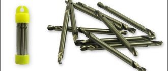
- Manufacturing of tools for processing wood, metal, concrete, plastic.
- Assembly of metal structures.
Iron-carbon alloys are divided into 2 large groups:
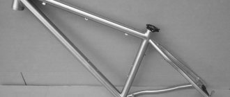
- Steel. A compound of carbon and iron. The mass fraction of carbon can reach 2.14% of the total amount. More often, its content does not exceed 1.5% of the total mass. Carbon steels are a strong, malleable, deformable structural material.
- Cast iron. An alloy based on carbon and iron. The content of the first component can reach 6.67% of the total amount. More often, its mass fraction does not exceed 5%. The properties of the material depend on the structure.
Types of cast iron:
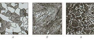
- Grey. The carbon included in the alloy is in the form of graphite. The material lends itself well to processing with tools and has high casting properties.
- White. Poorly processed. Most or all of the carbon is contained in the composition in the form of cementite. It is characterized by high hardness and poor weldability. Most often used to produce malleable cast iron.
- Highly durable. Carbon in such cast iron is contained in the form of spherical graphite, which is formed due to the crystallization process. Used for the production of parts that will be subject to heavy loads.
- Half-hearted. Carbon is contained in the form of graphite and cementite. Parts with increased wear resistance are made from it.
- Malleable. It is obtained by casting and heat treatment of white cast iron. Used for assembling agricultural machinery and cars.
A separate group should include special cast irons, the second name of which is ferroalloys. They contain manganese and silicon. Used for steel production. With their help, you can remove harmful impurities that impair technical characteristics.
Malleable cast iron figurine (Photo: Instagram / antikevro)
Types of alloys. Structural components of iron-carbon alloys.
three types of alloys: solid solution, mechanical mixture, chemical compound. If the atoms that make up an alloy of elements differ slightly in structure and size, they can form a common crystal lattice, then such an alloy is called a solid solution. If each element of the alloy crystallizes independently, then it is a mechanical mixture. If the elements of an alloy chemically interact to form a new substance, then such an alloy is called a chemical compound.
Depending on the temperature and carbon content, iron-carbon alloys may contain the following phases: austenite, ferrite, cementite and graphite. The structural components of their alloys can consist of these phases alone, as well as their mixtures (ledeburite - a eutectic mixture of austenite and cementite; pearlite - a eutectoid mixture of ferrite and cementite).
Austenite is a solid solution of carbon in γ-iron. The limiting carbon concentration in austenite is 0% at 1145°. With decreasing temperature, the solubility of carbon in austenite decreases to 0.08%. Austenite has this maximum concentration at 723°. This temperature is also the lower limit for the existence of stable austenite in carbon steels. Steel with an austenite structure is non-magnetic and has high ductility.
Ferrite is a solid solution of carbon in α-iron. Up to 0.02% carbon dissolves in α-iron at 700°; ferrite is characterized by insignificant values of hardness and strength and high ductility. The mechanical properties of ferrite strongly depend on the grain size.
Cementite is a chemical compound of iron and carbon (iron carbide) Fe3C. Cementite contains about 6.67% And and is very hard and brittle. Its hardness approaches HB - 800. Cementite is an unstable (endothermic) compound and can decompose under certain conditions.
Pearlite is a mechanical mixture of ferrite and cementite formed during the eutectoid decomposition of slowly cooled austenite. The carbon concentration in perlite is 0.80%. The hardness of pearlite HB is 180 ÷ 220. Steel containing 0.80% C has a purely pearlite structure.
Ledeburite is a mechanical mixture of austenite and cementite, formed during the crystallization of a liquid alloy containing 4.3% C. Since at a temperature of 723° austenite transforms into pearlite, this transformation also covers the austenite that is part of ledeburite. Thus, below 723° ledeburite is no longer a mixture of austenite and cementite, but a mixture of pearlite and cementite.
Graphite is free carbon located in the bulk of the metal in the form of plates or grains. It is formed either due to the decomposition of cementite, or is released from supersaturated liquid or solid solutions. In addition to the indicated structural components, other phases are observed in small quantities in technical iron-carbon alloys - sulfides, phosphides, oxides, nitrides and structural components based on them (for example, phosphide vtectic in cast iron).
80. State diagram of iron-carbon alloys (Fig. 5) . The main structures that make up iron-carbon alloys are as follows.
Ferrite is a solid solution of carbon in α-Fe. At a temperature of 723° C, the limiting carbon content is 0.02%. In the absence of impurities, it does not corrode.
Cementite - iron carbide Fe3C - a chemical compound containing 6.67% carbon. It is an integral part of the eutectic mixture, as well as an independent structural component. Capable of forming solid solutions by substituting atoms of other metals, unstable, decomposes during heat treatment. Cementite is very hard (HB 800) and brittle.
Austenite is a solid solution of carbon in γ –Fe. Carbon atoms are incorporated into the crystal lattice, and the saturation may vary depending on temperature and impurities. It is stable only at high temperatures, and with impurities of Mn, Cr - at ordinary, even low temperatures. The hardness of austenite is HB 170…220.
Rice. 5. State diagram of iron-carbon alloys:
a – diagram; I – liquid alloy; II – vein alloy and austenite crystals; III – liquid alloy and cementite; IV – austenite; V – cementite and austenite; VI – austenite, cementite, ledeburite; VII – cementite and ledeburite; VIII – ferrite and austenite; IX – ferrite and pearlite; X – cementite and pearlite; XI – pearlite, cementite; ledeburite; XII – cementite, ledeburite; b – approximate relationships of structural components in different areas of the diagram.
Pearlite is a eutectoid mixture of ferrite and cementite, formed by the decomposition of austenite at a temperature of 723 ° C and a carbon content of 0.83%. Si and Mn impurities promote the formation of pearlite even at lower carbon contents. The hardness of pearlite is HB 160…260. The structure of perlite can be lamellar and globular (granular).
Ledeburite is a eutectic mixture of austenite and cementite, formed at 1130° C and a carbon content of 4.3%. The structure is unstable: when cooled, the austenite included in ledeburite disintegrates into secondary cementite and pearlite. Ledeburite is very hard (HB 700) and brittle.
Graphite is a soft and brittle component of cast iron, consisting of varieties of carbon. Found in gray and ductile cast irons.
On the state diagram of iron-carbon alloys (Fig. 5), the temperature is plotted on the ordinate axis, and the carbon content in the alloys up to 6.67% is plotted on the abscissa axis, i.e. to such an amount that the chemical compound Fe3C – cementite – is formed. The dotted lines show the phase diagram for the iron-graphite system, since decomposition of Fe3C cementite is possible.
It is more correct to consider the diagram under consideration not as iron-carbon, but as iron-cementite, since the alloys do not contain free carbon. But since the carbon content is proportional to the cementite content, it is practically more convenient to associate all changes in the structure of the alloys with different carbon contents.
All lines in the diagram correspond to critical points, i.e., those temperatures at which structural changes occur in alloys. The critical points for steel were first discovered by the Russian metallurgist D.K. Chernov.
Line ACD is the line of the beginning of crystallization of the alloy (liquidus line), line AECF is the line of the end of crystallization of the alloy (solidus line). Only pure metals and eutectics melt and solidify at constant temperatures. The solidification of all other alloys occurs gradually, and the component that is excess in relation to the eutectic composition is first released from the liquid alloy. The AESG region in the diagram corresponds to austenite. Line GS is the beginning of ferrite precipitation, and line SE is secondary cementite. The PSK line corresponds to the final decomposition of austenite and the precipitation of pearlite. In the area below the PSK line, no changes in structure occur.
Depending on the carbon content, iron-carbon alloys receive the following names:
With a carbon content of <0.83% – hypoeutectoid steels
» » » 0.83% – eutectoid steels
» » » 0.83…2% – hypereutectoid steels
» » » 2.0…4.3% – hypoeutectic cast irons
» » » 4.3.. .6.67% – hypereutectic cast iron
With an increase in carbon content in iron-carbon alloys, the structure also changes, the cementite content increases and the amount of ferrite decreases. The more carbon in the alloys, the higher the hardness and strength, but the lower their plastic properties. The mechanical properties of alloys also depend on the shape and size of the particles of the structural components. The thinner and smaller the particles of ferrite and cementite, the higher the hardness and strength of steel.
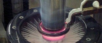
Industrial production
Iron-carbon alloys are produced by metallurgical plants from various components. The basis is iron with carbon. Stages of the production process:
- Preparation of consumable raw materials (ore). It is sorted by piece size and chemical composition. Low-grade ores are enriched with the required components. Waste rocks are removed.
- Fuel preparation. Coke coal undergoes a screening procedure. It is needed to remove foreign impurities from the fuel, which can lead to heat losses during ore smelting.
- Flux preparation. Substances that will be used for the production of cast iron are crushed. At the same time, fines are sifted out and foreign impurities are removed.
- Loading consumables and ore into the blast furnace. First, it is filled with coke, ore is laid out on top, and another layer of coke is poured on top of it. Heated air is blown inside to maintain the melting temperature of the metal. When coke burns, a large amount of carbon dioxide is released, which passes through the coke residues, forming the compound CO. During the reduction process, the iron gains hardness. Gradually the carbon begins to dissolve. Liquid cast iron is fed to special ladles, from which it is poured into molds.
Large blast furnaces are used to produce cast iron. Their height can reach 30 m, and their internal diameter is 12 m.
Blast furnace (Photo: Instagram / viktormacha)
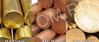
Alloy components
Technical characteristics of iron-carbon alloys depend on the type and amount of alloying additives:
- Carbon. The composition is present in the form of cementite, graphite, iron carbide. This component is introduced specifically to give the material hardness, strength, and change technical characteristics for the better.
- Manganese, silicon. Useful impurities that are specially introduced into the alloy (a certain part of them comes from the ore). They reduce the fragility and hardness of alloys, increasing its strength and wear resistance.
- Phosphorus, sulfur. Harmful impurities for iron-carbon alloys. Manufacturers are trying to reduce their number. With a high content of these impurities, fragility and hardness increase, casting properties deteriorate, and shrinkage appears when the molten metal cools.
Iron-carbon alloys: phase and structural state
IRON-CARBON ALLOYS: PHASE AND STRUCTURAL STATEIron-carbon alloys, steels and cast irons have been the basis for the development of human civilization for an entire era. And this is due, on the one hand, to the high abundance of iron in the earth’s crust, and on the other, to the unique properties of iron-based alloys.
Such properties are achieved through the interaction of iron with carbon, as well as with numerous alloying elements, which significantly change the structure and phase composition of iron-carbon alloys. The phase and structural state of these alloys is described by the iron-carbon diagram.
Understanding the Iron-Carbon Diagram
In the iron-carbon system, several types of alloys can be distinguished: iron, steel and cast iron. Unlike pure, technically pure iron contains up to 0.025% carbon, as well as in small quantities silicon, manganese and some other elements. Steels contain up to 2% carbon, cast irons – more than 2%.
Pure iron
Iron is a ferromagnetic transition polymorphic metal, with a serial number in the table D.I. Mendelev 26. Electronic structure: 1S2 2S2 2p6 3s2 3p6 3d6 4s2.
The melting point of pure iron is 1539 °C. Density at room temperature 7.684 g/cm3, atomic mass 55.85. The structure of iron consists of equiaxed polyhedra separated by thin veins of grain boundaries. Pure iron has relatively large grains. Technical iron is an alloy of iron with carbon if the carbon content in them does not exceed 0.02% (by weight). An increase in the amount of impurities, including carbon, refines the grain size and increases the thickness of the boundaries. In industrial iron, veins of tertiary cementite may be identified along grain boundaries. Iron has a number of critical points (A4 = 1392 ˚С, A3 = 911 ˚С), corresponding to polymorphic transformations, as well as a polymorphic transformation point (Curie point - 770 ˚С).
At temperatures below 911˚C, iron has a body-centered cube (BCC) lattice, the lattice parameter is 2.8605 kX at 20˚C. This modification is called alpha iron. Up to 770 ˚ C, alpha iron is ferromagnetic, above it is paramagnetic. Ferromagnetism disappears at the Curie point temperature without any change in the crystal structure. The Curie point does not have thermal hysteresis, i.e. When iron is cooled below 770˚ C, ferromagnetism is restored.
The temperature 911 ˚ C is the critical point (A3) at which the polymorphic transformation aFe ÛgFe occurs. When heated to a temperature above 911 ˚ C, a restructuring of the crystalline structure of iron occurs from the lattice of a body-centered cube into a lattice with a more dense packing of atoms - a face-centered cube (fcc) - gamma iron. The transformation of aFe ®gFe is accompanied by a decrease in specific volume by approximately 1%. The fcc lattice parameter of γ-iron is 3.6409 kX at 950 ˚ C.
Under equilibrium conditions with very slow heating, the lattice rearrangement from alpha to gamma iron begins approximately 10 ˚ C higher than when alpha is formed from gamma iron with very slow cooling. Therefore, in order to distinguish the temperatures at which transformations begin, additional indices c and r are used for heating and cooling, respectively. In this case, the designation of the critical points is Ac3 and Ar3, respectively, during heating and cooling. The difference in temperature values of Ac3 and Ar3 is called temperature transformation hysteresis.
Gamma iron exists in the temperature range 911–1392 ˚ C. Temperature 1392 ˚ C (A4) is the critical point at which the restructuring of gFe ÛdFe occurs. Delta iron, existing before the melting point, has a lattice similar to alpha iron, a body-centered cube lattice, differing from alpha iron in the lattice parameter (2.93 kX at 1425 ˚ C). Gamma and delta iron are paramagnetic.
Iron-carbon systems
The interaction of iron and carbon, the nature of the phases, the nature of the phase equilibrium in the system and the iron-carbon diagram itself are determined by the electronic structure of iron and carbon.
Iron in the metallic state under real conditions, described by the iron–carbon diagram, gives up its two outer valence electrons with the 4s2 shell to the itinerant state. The d6 orbitals that open in this case overlap with the electron shell, forming a body-centered cube (BCC) lattice. This electronic structure is characteristic of alpha and delta iron.
In the temperature range from 911 to 1392 ˚ C d6 - orbitals do not overlap, and therefore the spherical symmetric electronic configuration of the electron shell ensures the formation of a dense packing of a face-centered cube, corresponding to the gamma-iron lattice.
The electronic configuration of carbon atoms is 1S2 2S2 2p2. The four electrons on the outer shell can either go into a collectivized state during the formation of solutions, or take part in valence bonds during the formation of chemical compounds. In addition, the outer shell of carbon can be filled to the 2S2 2p6 level when metal carbides are formed.
Carbon in systems with iron at normal pressure can be in a free state in the form of graphite, as well as in a dissolved state in solid and liquid solutions. In addition, it forms carbides, such as cementite Fe3 C.
Cementite is a compound with a predominant covalent bond, reinforced by a small proportion of ionic bonding between iron and carbon ions, as well as a metallic bond. The presence of some metallic bond in cementite determines its conductivity due to the appearance of a certain electron concentration in connection with it.
During the formation of cementite, electrons are exchanged between neighboring iron and carbon atoms, one d-electron of the Fe2+ ion with the d6 configuration and an electron of the outer shell of the carbon atom. At the carbon atom, six valence electrons captured in the 2p level take part in the formation of bonds. The six orbitals of the 2p6 shell overlap with the six d-orbitals of the six nearest iron atoms (d6). In this case, six exchange two-electron bonds of the covalent type arise, determining the predominant covalent bond in the cementite lattice.
Graphite has a hexagonal layered structure due to the formation of one-and-a-half bonds between carbon atoms.
When carbon dissolves in iron, its atoms lose valence electrons, which are collectivized and go into electron gas along with iron electrons. The 1S2 electronic configuration of the carbon ion, which is exposed in this case, acquires a spherical configuration and has a very small size (about 1.1 kX). This allows carbon ions to be located in the octahedral voids of fcc and bcc iron lattices, forming interstitial solid solutions: g-solid solution (austenite), a-ferrite and d-ferrite.
Liquid solutions of carbon in iron above the melting point of alloys in the iron-carbon system have the same electronic structure as solid solutions: d-ferrite and g-austenite. During melting, the same short-range order in the crystal structure of the alloys is preserved, which was observed before melting in the given alloy in the solid state. During melting, only long-range order is disrupted.
The phase states of iron-carbon alloys, depending on composition and temperature, are described by diagrams of stable and metastable equilibrium. Thermodynamic analysis shows that the most stable system formed by two components: iron and carbon, is the iron-graphite system. The iron-cementite system is metastable.
The iron - graphite diagram was constructed under conditions of very slow heating and cooling (fractions of a degree per minute). The iron-cementite diagram is constructed under conditions of higher heating and cooling rates (of the order of several degrees per minute).
The diagrams make it possible to describe both the phase composition and structure of the alloy. In this case, the diagram is called, respectively, phase or structural. Often the designations for the phase and structural composition of alloys are combined.
Characteristics of phase and structural components of iron-carbon alloys
In accordance with the previously given definitions of the phase and structural components of the system, in the iron-carbon system the phase components include: liquid solution (L), solid solutions: ferrite (α), austenite (γ), high-temperature ferrite (δ), as well as cementite and graphite (G).
The liquid solution in the iron-carbon system is a solution of carbon in molten iron. At temperatures significantly above the liquidus line (mainly above 1700˚ C), the liquid is a statistically disordered solution with a statistically dense packing. With slight overheating above the liquidus line, the liquid solution has a relatively regular structure. The liquid solution formed during the melting of δ-ferrite (up to 0.51% carbon) maintains short-range order in the bcc lattice of δ-iron. The liquid solution formed during the melting of austenite has a short-range order corresponding to the fcc lattice of γ-iron.
Ferrite is a solid solution of interstitial carbon in α-iron. The ferrite lattice is a body-centered cube with the arrangement of carbon atoms in relatively small octahedral voids of the lattice, which greatly distorts it. The solubility of carbon in ferrite is low.
At a temperature of 727 ˚ C, 0.02% C dissolves in ferrite; as the temperature decreases, the solubility decreases, reaching a value of 0.006% C at room temperature. The ferrite structure consists of relatively equiaxed polyhedral crystals separated from each other by thin high-angle boundaries. The structure of ferrite is usually revealed by etching with nitric acid solutions.
Ferrite up to the Curie point temperature (770˚C) is highly ferromagnetic and conducts heat and electric current well. In the equilibrium state, ferrite is plastic (relative elongation of the order of 40%), has low strength and hardness (HB = 65 - I30, depending on the grain size).
Ferrite, depending on the nature of the ongoing phase transformations, in the structure of iron-carbon alloys can be in the form of various structural states: ferrite, as the basis of the alloy structure (F); ferrite, as the second (excess) phase, located along the boundaries of pearlite colonies, in the form of separate equiaxed or needle-shaped inclusions; ferrite, which is included as a phase in the composition of another structural component - pearlite or ferrite-graphite eutectoid.
At temperatures above the critical point A4, the modification of high-temperature δ-ferrite becomes stable, which, like low-temperature α-ferrite, has a body-centered cubic lattice, but with larger parameters in comparison with it. δ-ferrite is paramagnetic.
Austenite is a solid solution of interstitial carbon in γ-iron. The austenite lattice is a face-centered cube (FCC). The carbon atoms are located in large octahedral lattice voids.
The solubility of carbon in austenite is significantly higher than in ferrite: 2.03 and 2.14% at eutectic transformation temperatures, respectively, in a stable and metastable system. As the temperature decreases, the solubility decreases to 0.69 and 0.80% in the mentioned systems, which corresponds to the temperatures of the eutectoid transformation in both systems.
Austenite is revealed in the structure in the same way as ferrite in the form of relatively equiaxed polyhedra, but differs from it in a significant number of twins in the body of the grain. Austenite is a paramagnetic component throughout the entire temperature range of its existence. Austenite is soft, although harder than ferrite (HB = 200-250). It is plastic (relative elongation 40-50% and above). The transformation of ferrite and ferrite-cementite mixture into austenite is accompanied by a decrease in volume.
The structural state of austenite (A) in iron-carbon alloys is similar to ferrite: it can be the only structural component in the alloy; form the basis of the alloy; enter into it as retained austenite; be contained as a phase component in the composition of a more complex structural component - a eutectic austenite-cementite mixture (ledeburite), which exists at temperatures above the eutectoid line on the iron-carbon diagram.
Cementite is a metastable compound of iron and carbon, corresponding to the formula Fe3 C. Cementite has a complex orthorhombic lattice, the base of which is a trihedral, slightly distorted prism formed by six iron atoms. Some iron atoms have 11 neighboring iron atoms, and some have 12. The voids are filled with carbon atoms. In this case, the structure of cementite is close in its structure to the structure of austenite, as well as to the densest hexagonal modification of ε - iron.
Cementite is a compound of almost constant composition. The solubility of iron in cementite occurs, but its value is very small and practically insignificant. With increasing temperature, cementite relatively easily decomposes into iron (austenite or ferrite) and graphite. This property of cementite underlies the phenomenon of graphitization, and is used to produce gray and ductile cast irons. Cementite is brittle, very hard (HB about 800), weakly magnetic up to a temperature of 210˚C. Above this temperature, cementite is paramagnetic.
The structural state of cementite is determined mainly by the type of transformation during which it is formed. There are primary cementite (CI), which are large needle-shaped crystals formed during crystallization directly from liquid in hypereutectic white cast iron. Secondary cementite (CII) is released in hypereutectoid steels and hypoeutectic cast irons, mainly in the form of a network along the boundaries of austenite grains, and also in some cases in the form of coagulated particles or needles uniformly distributed throughout the volume of the austenite grain. Secondary cementite is an excess phase in iron-carbon alloys that is released from austenite during cooling as a result of a decrease in the solubility of carbon in austenite with decreasing temperature.
The precipitation of tertiary cementite (CIII) is typical for industrial iron and low-carbon steel. Tertiary cementite is released from ferrite as a result of a decrease in the solubility of carbon in ferrite with a decrease in temperature from 727˚C to room temperature. Tertiary cementite in the structure of iron and low-carbon steel in the microstructure is observed in the form of thin veins along the boundaries of ferrite grains. Such precipitation of tertiary cementite embrittles iron and low-carbon steels. Therefore, such alloys are subjected to heat treatment in order to change the structural state of tertiary cementite. Its desired position in the structure of the alloy is uniformly dispersed precipitation in the volume of ferrite grains. This is achieved through hardening and aging.
In addition, cementite as a phase component is included in the complex two-phase structural components in iron-carbon alloys - pearlite and ledeburite. In this case, such cementite is called eutectoid and eutectic (Tse), respectively.
Graphite is the most important phase and structural component (G) of gray, malleable and high-strength cast irons, which determines their low shrinkage during crystallization, high anti-friction properties, low wear, high internal friction, which reduces vibration, and a number of other useful properties. Graphite is a hexagonal modification of carbon. At normal pressure, graphite is a stable component up to temperatures of about 4000˚C.
In the graphite lattice, the atoms are arranged in layers with hexagonal symmetry. In the first and third layers, the atoms are located on top of each other. In the second (middle) layer, the atoms are shifted along the largest diagonal of the hexagon by the value of the lattice parameter (the length of the side of the hexagon). The distance between the layers (3.35 kX) is significantly greater than the distances between neighboring atoms in a hexagonal layer. Due to the easy mobility of weakly bonded hexagonal layers, graphite is the least strong phase of iron-carbon alloys.
Graphite in the structure of iron-carbon alloys is either in the form of an excess phase (in hypereutectic gray cast iron) or as a phase component included in the austenite-graphite eutectic. Graphite has the form of branched crab-shaped inclusions. Eutectic graphite differs from primary graphite in its smaller size and greater branching.
After modifying liquid cast iron with magnesium and some other elements, as well as after annealing white cast iron into malleable iron, globular (flaky or spheroidal) graphite can be observed in the structure. This form of graphite provides increased strength and ductility of cast iron.
All the described phase components can simultaneously be structural components if they are in the form of excess phases in the alloy structure or form the basis of the alloy structure.
In addition to single-phase structural components, iron-carbon alloys also contain complex two-phase ones: pearlite, ledeburite, graphite-austenitic eutectic and ferrite-graphite eutectoid.
Pearlite is a eutectoid physicochemical mixture of two phases: ferrite and cementite, formed in a metastable iron-carbon system due to the diffusion separation of austenite according to the eutectoid reaction. Pearlite is formed when austenite is supercooled below the PSK line of the iron-carbon diagram. The structure of perlite is determined by the amount of supercooling at which decomposition occurs.
At low supercooling (20-30 ˚С below the eutectoid transformation line), granular pearlite is formed. Granular pearlite is a ferrite-cementite structure in which the base is ferrite, and granular, close to spherical, cementite inclusions are statistically evenly distributed throughout its volume.
With greater supercooling, a structure of lamellar pearlite is formed, consisting of regularly alternating plates of cementite and ferrite, and the ferrite plates are approximately 7 times thicker than the cementite plates.
The absolute values of the thickness of cementite and ferrite plates, the distance between the same plates in the eutectoid mixture, called the interplate distance, and characterizing the degree of dispersion of the structure, are determined by the degree of overcooling of austenite below the equilibrium temperature of the eutectoid reaction. The greater the degree of supercooling, the higher the dispersion of the ferrite-cementite eutectoid mixture. Highly dispersed ferrite-cementite mixtures are called sorbitol and troostite. Troostite is the most dispersed ferrite-cementite mixture.
Pearlite is present in the structure of steels and cast irons. The amount of pearlite increases in hypoeutectoid steels with increasing carbon content from 0.02 to 0.8%. Eutectoid steel has a purely pearlitic structure (100% pearlite).
A further increase in the carbon content in steel, corresponding to the transition to hypereutectoid steels, and then to cast irons, is accompanied by a decrease in the proportion of pearlite in the structure due to the appearance and increase in the amount of secondary, eutectic and, finally, primary cementite.
Pearlite in low-carbon steels appears first in the form of separate inclusions between ferrite grains, then, as its quantity increases, it gradually occupies an increasingly larger field of view in the structure on the surface of the section. While there is little pearlite in the structure, its structure is not revealed at low and medium magnifications of an optical microscope. In eutectoid and hypereutectoid steels, its lamellar structure is revealed even at low magnifications (×100 - 200). In the structure of cast iron, pearlite is found both in the form of excess colonial structural components - products of the decomposition of excess austenite, and in the composition of ledeburite. The mechanical properties of pearlite are determined by its structural state. Calculation according to the rule of additivity of pearlite hardness, based on the known values of ferrite and cementite hardness, gives values of 150-180 HB. The experimentally determined hardness values of lamellar perlite, sorbitol and troostite are respectively 170 - 230, 230 - 330 and 330 - 400 HB. Thus, it can be seen that the higher the degree of dispersion of the ferrite-cementite mixture, the higher its hardness.
Ledeburite is a eutectic physicochemical mixture of austenite and cementite, formed as a result of eutectic crystallization from a liquid containing 4.3% carbon.
Ledeburite is a colonial structure, the basis of which is made up of cementite plates overgrown with branched austenite crystals. Austenite branches in the composition of ledeburite are located regularly throughout the entire volume of the eutectic cementite plate and have the form of rods of approximately cylindrical configuration. On a thin section, a colony of ledeburite, depending on the direction of the surface of the thin section relative to the austenitic branches, can look either in the form of a “granular” mixture in the cross section of the colony, or “platelike” in the longitudinal section. When the colony is sectioned at an angle to the plane of the cementite base, the sections of the austenite branches in the composition of ledeburite are of an elliptical configuration.
In addition to colonial (honeycomb) ledeburite, a eutectic mixture of austenite and cementite can occur in the form of lamellar eutectic, which is a package of thin cementite plates separated by austenite. Such packets are formed by two intertwined crystals of cementite and austenite. The probability of formation of lamellar ledeburite increases with increasing degree of supercooling of the liquid during crystallization. At the same time, the proportion of lamellar ledeburite in the structure of white cast iron increases. Most often, a packet of lamellar ledeburite forms the basis on which a colony of honeycomb ledeburite nucleates and grows.
At very high cooling rates, all ledeburite may turn out to be platelike. In this case, cementite branches, taking on the appearance of fan-shaped colonies. At even higher cooling rates, spherulite colonies appear. Ledeburite, consisting of a eutectic mixture of austenite and cementite, is stable in the temperature range from the eutectic to the eutectoid line on the iron-carbon diagram. When the temperature drops below 727 °C, the austenite in ledeburite undergoes a eutectoid transformation, as a result of which at room temperature ledeburite is a eutectic mixture of pearlite and cementite. The structure of pearlite in ledeburite is the same as in alloys with lower carbon content (steels).
Ledeburite, like the cementite that forms its base, is hard, wear-resistant and has practically zero ductility. These properties of ledeburite underlie the use of this structure in white cast irons, which are used as one of the most wear-resistant materials.
Austenitic-graphite eutectic is formed in a stable iron-carbon system and is a mixture of graphite crystals, formed during the simultaneous release of both phase components from a liquid with a composition of 4.25% carbon. At low degrees of supercooling, eutectic graphite has, like primary graphite, a branched lamellar shape. An increase in the cooling rate leads to splitting of the graphite plates and the formation of spherical crystals. The eutectic austenite-graphite structure differs little from the separation of primary graphite crystals. The main difference between these structures is the size of the graphite inclusions. They are smaller in the eutectic than the primary crystals.
Ferrite-graphite eutectoid is a product of eutectoid decomposition of austenite containing 0.69% carbon, which is realized under very slow cooling conditions at temperatures below 738˚C.
Ferrite-graphite eutectoid is a dispersed mixture of ferrite, which forms the basis of the alloy structure, and dispersed branched or spherical graphite particles, statistically evenly distributed in the ferrite. However, in most cases, eutectoid graphite, during the decomposition of austenite, is deposited on previously formed primary and eutectic graphite crystals. The eutectoid transformation with the formation of a ferrite-graft eutectoid is used in the heat treatment of cast iron and graphitized steel to obtain a ferrite-graphite structure with good antifriction properties while maintaining a sufficiently high ductility of the alloys.
Characteristics of the main points and lines of the iron-carbon diagram
All points on the iron-carbon diagram have a certain physical meaning and letter designations generally accepted in world practice. Knowledge of the basic properties and characteristics of these points makes it easier to understand the diagram and its practical use. Below are brief characteristics of the points and lines of the diagram.
Key points of the iron-carbon diagram
A is the point corresponding to the melting - crystallization of pure iron. The temperature corresponding to this point is 1539 °C. The number of degrees of freedom at this point is zero. On thermal curves for pure iron, the temperature of point A corresponds to horizontal areas that arise due to the release of latent heat of crystallization. The transition from the solid to the liquid state, corresponding to point A, is accompanied by a sharp increase in volume (about 6%), associated with a violation of long-range order in the crystal structure of d-iron. When pure iron crystallizes at this point, the opposite phenomena are observed.
B is the point of maximum saturation with iron of a liquid solution that is in equilibrium simultaneously with crystals of d- and g-solid solutions at peritectic temperature. Point B corresponds to a carbon content in the liquid of 0.51%, a temperature of 1496 °C.
C – eutectic point in the metastable system Fe – Fe3 C. Temperature 1147 °C, carbon concentration corresponding to point C – 4.3% – this is the carbon content in the liquid solution, which is in equilibrium simultaneously with austenite and cementite during the eutectic transformation. The number of degrees of freedom corresponding to this point is zero. On the thermal cooling and heating curves, point C corresponds to horizontal areas similar to the melting areas - crystallization of pure iron.
C¢ is the eutectic point in the stable iron-graphite system. The temperature corresponding to the point 1153 °C, the carbon concentration is 4.25% - this is the carbon content in the liquid that is in equilibrium with austenite and graphite during eutectic crystallization. As at point C, at this point the system is invariant.
D – according to the accepted notation, point D is referred to as the melting point of cementite. However, known data indicate that cementite is a thermodynamically unstable phase, and therefore, before melting, it decomposes into iron and graphite. In this case, the position of point D on the diagram turns out to be uncertain.
D¢ – point corresponding to the melting temperature of graphite (about 4000°C).
E is the point corresponding to the limiting carbon content in austenite, which is in equilibrium with cementite and liquid at the eutectic temperature (1147 °C) in a metastable system. Carbon content value 2.14%. Point E on the concentration axis of the diagram is a kind of boundary between steel and cast iron. When the carbon content in alloys is less than 2.14%, there is no ledeburite in their structure; with a carbon content of more than 2.14%, ledeburite is present in the structure of the alloys. This is the most important structural component of cast iron.
E¢ is the point corresponding to the limiting carbon content in austenite, which is in equilibrium with graphite and a liquid solution at the eutectic temperature (1153 °C) in a stable system. The carbon content corresponding to this point is 2.03%.
F is the point of maximum saturation of cementite with iron at the eutectic temperature (1147°C). The value of carbon concentration corresponding to point F is practically close to 6.67%, although recent work shows the presence of some very low solubility of iron in cementite.
F¢ is the point of maximum saturation of graphite with iron at the eutectic temperature (1153 °C).
G – point of polymorphic transformation in pure iron aÛg. Transformation temperature 911°C. The number of degrees of freedom of the system at this point is zero. The restructuring of the crystal lattice a®g is accompanied by a decrease in volume, the reverse transition g®a increases the specific volume of the sample, which is associated with different packing densities of atoms in the face-centered lattice g—iron and the body-centered lattice a—iron. Point G corresponds to critical point A3 for pure iron.
H is the point of maximum saturation of d-ferrite with carbon at the peritectic transformation temperature. The temperature corresponding to this point is 1496 °C, the carbon concentration is 0.10%, which corresponds to the concentration of d-ferrite in equilibrium with austenite and liquid at the peritectic temperature.
I – peritectic point, a point of three-phase equilibrium, corresponding to the equilibrium concentration of austenite formed by a peritectic reaction under isothermal conditions from a liquid of the composition of point B and d-ferrite of the composition of point H. The temperature at point I is 1496 ° C, the carbon concentration is 0.16 %.
K is the point of maximum saturation of cementite with iron at a eutectoid temperature of 727°C. The point practically corresponds to a concentration of 6.67% carbon.
K¢ is the point of maximum saturation of graphite with iron at the eutectoid temperature (738°C).
M is the Curie point of pure iron. The temperature of this point is 770 °C. The point corresponds to the loss of ferromagnetism of a-iron when heated and the restoration of its ferromagnetism when cooled.
N is the point of polymorphic transformation dÛg in pure iron. Transformation temperature 1392 °C. Point N for pure iron corresponds to the critical point A4. At this point the system is nonvariant.
O is the point of greatest solubility of carbon in austenite in contact with non-magnetic ferrite at a temperature of 770 °C. The carbon content of austenite at this point is approximately 0.5%.
P is the point of limiting carbon content in ferrite, which is in equilibrium with cementite and austenite at eutectoid temperature (727°C). The carbon content value for this point is 0.02%. Point P on the concentration axis of the diagram separates industrial iron from steel. Steels (carbon content above 0.02%) contain pearlite as a structural component. In technical iron (carbon content no more than 0.02%), there is no perlite.
S – eutectoid point in a metastable system. The temperature corresponding to this point is 727 °C, carbon content 0.8%. This is the carbon content in austenite that is in equilibrium with ferrite and cementite in a eutectoid reaction. The number of degrees of freedom, as for other three-phase reactions in this system, is zero.
S¢ is a eutectoid point in a stable iron-graphite system. The temperature corresponding to this point is 738 °C, the carbon content in austenite corresponding to point S¢ç is 0.69%. This is the carbon content in austenite, which is in a state of equilibrium with ferrite and graphite at the moment of development of the direct or reverse eutectoid transformation. The system at the point S¢ç is nonvariant.
Q is the point of limiting solubility of carbon in ferrite (value 0.006% at room temperature). An increase in the carbon concentration in ferrite to values greater than 0.006% leads to a change in the phase composition and, first of all, to the appearance of tertiary ferrite in the structure.
Classification
Steel is classified according to different criteria. By chemical composition:
- High carbon - more than 0.65% C.
- Medium carbon - from 0.25% to 0.65% C.
- Low carbon - less than 0.25% C.
By structure:
- hypereutectoid;
- eutectoid;
- hypoeutectoid;
- ledeburite.
By purpose:
- Instrumental. Used in the manufacture of working parts and accessories for electrical tools and industrial equipment.
- Structural. They are used in the manufacture of metal structures, parts of industrial equipment, and machines.
Steel in rolls (Photo: Instagram / mmz_sim)
Classification of iron-carbon alloys
The structure of alloys in the equilibrium state is determined by the carbon content. According to the carbon content in the “Iron - cementite” diagram, all alloys are usually divided into three groups: technical iron, steel and cast iron.
Technical hardware
are called alloys with a carbon content from 0 to 0.02%.
At a carbon concentration of up to 0.006%, the alloys are single-phase
and have a ferrite structure.
Alloys with carbon content from 0.006% to 0.02% are two-phase
. This is explained by the fact that the concentration of carbon in the alloys exceeds its solubility in ferrite at room temperature. During the cooling process, the ferrite of any alloy having a carbon concentration above 0.006% becomes oversaturated. The ferrite will reach an equilibrium state due to the release of cementite.
Steel
are called alloys of iron with carbon, the concentration of which ranges from 0.02% to 2.14%.
The processes occurring during primary crystallization do not affect the structure of steels. The final structure of steels is formed from austenite. At 727 ºС (Fig. 4.4.1, line РСК) all steels undergo eutectoid
transformation:
A0.8% C → P (F0.02% C + C6.67% C).
The product of this transformation is perlite
– eutectoid mixture of ferrite and cementite.
According to their structure in the equilibrium state, steels are divided into:
· to hypoeutectoid
(carbon concentration from 0.02% to 0.8%), at room temperature, consisting of two phases - ferrite and cementite, the structure of such steels is ferrite + pearlite;
e vtectoid
(carbon concentration 0.8%), also consisting of two phases - ferrite and cementite, structure - pearlite;
· hypereutectoid
(carbon concentration from 0.8% to 2.14%), having a pearlite + cementite structure, formed from two phases - ferrite and cementite.
Cast iron
are called iron-carbon alloys containing more than 2.14% carbon.
If all the carbon is in a chemically bound state (in the form of the chemical compound Fe3C
), then such cast iron is called
white
. This type of cast iron owes its name to the color of the fracture.
White cast irons are characterized by a eutectic transformation at a temperature of 1147 ºС (Fig. 4.4.1, ECF line), as a result of which ledeburite
– eutectic mixture of austenite and cementite:
F4.3% C → L2.14% C + C6.67% C.
At a temperature of 727 ºС, austenite transforms into pearlite, and after this ledeburite will consist of pearlite and cementite.
According to their structure in the equilibrium state, cast irons are divided into:
· to hypoeutectic
(from 2.14% to 4.3% carbon). Phase composition – ferrite and cementite; structural composition – ledeburite, pearlite, secondary cementite;
· eutectic
(4.3% carbon). Phase composition – ferrite and cementite, structural composition – ledeburite;
· hypereutectic
(from 4.3 to 6.67% carbon). Phase composition – ferrite and cementite, structural composition – ledeburite, primary cementite.
All the alloys discussed above consist of the same phases - ferrite and cementite, but have different structures, and it is the structure that determines the properties of the alloys.
White cast irons have good casting properties, but their high hardness precludes their mechanical processing. Therefore, white cast iron is not a structural material. High casting properties are provided by carbon, and at the same time, carbon, combining with iron, forms solid cementite.
To maintain high casting properties and reduce the hardness of cast iron, it is necessary, without reducing the carbon concentration, to achieve a sharp reduction in the cementite component in the structure. To do this, it is necessary that all or most of the carbon is released in free form in the form of graphite. This problem is solved by introducing silicon into the alloy and slowly cooling the casting.
Gray
Cast irons are alloys of iron and carbon in which all the carbon or most of it is in a structurally free state in the form of lamellar (petal) graphite. Since gray cast irons are, at a minimum, three-component alloys, the “Iron - cementite” diagram is not suitable for determining the structure of alloys. In gray cast iron, a metal base and graphite inclusions are distinguished.
Based on the metal base, gray cast irons are divided into:
· for ferritic gray cast iron with a ferrite and lamellar graphite structure;
· for ferrite-pearlite gray cast iron with the structure of ferrite, pearlite, lamellar graphite;
· for pearlitic gray cast iron with the structure of pearlite and lamellar graphite.
Gray cast irons have good casting properties and are excellent for cutting, but have low strength and poor resistance to impact loads. The low strength of gray cast iron is due to the shape of the graphite. Lamellar graphite serves as a stress concentrator, acting as a notch.
To preserve the advantages of gray cast iron and increase its strength, it is necessary to change the shape of the graphite - turn the plates into globules. This problem is solved by modification - introducing small amounts of magnesium or cerium into the melt.
Highly durable
Cast irons are alloys of iron and carbon in which all the carbon or most of it is in a structurally free state in the form of spherical graphite.
Based on the metal base, high-strength cast irons are divided into:
· for ferritic high-strength cast irons with a ferrite and nodular graphite structure;
· ferrite-pearlite high-strength cast irons with the structure of ferrite, pearlite and nodular graphite;
· pearlitic high-strength cast irons with the structure of pearlite and nodular graphite.
Forged
Cast irons are alloys of iron and carbon in which all the carbon or most of it is in a structurally free state in the form of flake graphite. Malleable cast iron is obtained by annealing white cast iron.
Based on their metal base, malleable cast irons are divided into:
· for ferritic malleable cast irons with a ferrite and flake graphite structure;
· ferrite-pearlite malleable cast irons with the structure of ferrite, pearlite and flake graphite;
· pearlitic malleable cast irons with the structure of pearlite and flake graphite.
Properties
Characteristics of iron-carbon alloys:
- Density - up to 7.9 g/cm3.
- Melting point - up to 1520 °C.
- Specific heat capacity - 462 J/(kg °C) at an ambient temperature of no more than 20 °C.
- Specific heat of fusion - 84 kJ/kg.
- Thermal conductivity coefficient is 30 W/(m K) at a temperature of 100 °C.
- The coefficient of linear thermal expansion is 11.5·10-6 1/°C.
Iron-carbon alloys are produced by industrial enterprises. These include different types of steel and cast iron. They are used in various industries.