Operating principle
Centrifugal pumps are one of the most common machines in the industry. In terms of quantity, they are second only to electric motors. Because Since electric motors are used to drive pumps, it can be said that the lion's share of the world's electricity is spent on transporting liquids by centrifugal pumps.
Centrifugal pumps get their name from the way in which energy is transferred to the fluid.
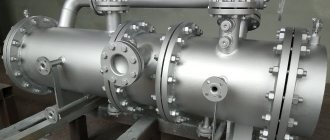
As liquid is introduced to the pump, it comes into contact with the rotating impeller and is forced into the discharge pipe by centrifugal force through a specially shaped cavity called a spiral casing . All centrifugal pumps operate on this principle, but there may be design differences among them.
The pump transfers kinetic energy to the fluid . Kinetic energy refers to the speed of the fluid . Speed is only half the equation.
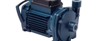
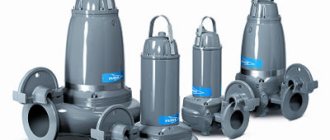
Fig. 1 – Centrifugal pump
The liquid enters the pump through the center of the wheel through the suction port. The friction between the fluid particles and the impeller causes the fluid to rotate. For example, how friction between the road and the rubber of a tire makes a car move.
The impeller pulls the fluid particles so they rotate when they come into contact with them. The fluid is pushed out of the wheel by centrifugal force - a phenomenon that pushes any object away from the center of the circle towards its borders. This is how the fluid receives kinetic energy from the wheel.
Therefore these pumps are called centrifugal .
The amount of energy transferred to a fluid depends on three factors:
- liquid density:
- impeller rotation speed:
- impeller diameter:
After the impeller, the liquid enters the cavity of the volute housing, from where it enters the pressure pipe.
Pressure . The pump must also produce positive pressure to meet the system requirements. Usually this is overcoming gravity when lifting liquid from a lower level to a higher one, and the frictional resistance of pipelines.
Simply put, pressure is the ability to complete a task . And the speed of the fluid is how quickly it will be completed.
Pumps must convert dynamic pressure into static pressure.
As the fluid passes through the spiral casing, it slows down as the passage area increases, because the productivity or the amount of fluid pumped over time depends on two factors: the first is the speed of the fluid, the second is the size of the cavity through which it moves .
If the flow is constant, then an increase in the flow area leads to a decrease in speed and an increase in pressure . Upon reaching the pressure port, most of the kinetic energy is converted into pressure.
By the way, read this article too: Peristaltic (hose) pump operating principle
If the speed drops, the pressure increases.
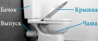
How does a circulation pump work?
The private houses in which our parents live were built with their own hands, which is noticeable in the illiterate layout of the premises, not always straight windows and doors, and littered walls. Everyone installed the heating as they understood, the principle was the same: the slope must be maintained so that water could continuously circulate through the system.
The operation of the circulation pump takes us into a new era of heating systems. Its presence in the system makes it much more economical. The diameter of the pipe can be significantly smaller, which significantly reduces the volume of coolant. The liquid moves through the heating system at a certain speed, which allows you to heat the rooms evenly, maintain the most comfortable temperature in them, and, if necessary, it heats up quite quickly. The automatic operating mode of the circulation pump allows the device to instantly respond to various changes in the system, changing the device settings and making the operation of the heating equipment more economical. Heating a house with several floors is unthinkable without such a pump, and the continuous circulation of the coolant, in addition to all these advantages, also protects the heating boiler from erosion.
Design
A pump is a machine that converts mechanical energy into kinetic energy, pumping fluid and electrically transporting it from one point to another.
A centrifugal pump consists of two main components.
- The first is a rotating disk with curved blades. It is called an impeller .
- The second is a specially shaped pipe called a volute casing , which contains the impeller and transport fluid .
There are 5 design elements that may vary:
- type of wheel;
- type of bearing;
- housing location;
- engine mount;
- number of steps.
Areas of application
It is difficult today to find a sector of everyday life or industry that uses liquid media and does not use centrifugal pumps. The most popular areas of application are:
- Water supply of all levels and scales - from water intake stations to industrial enterprises and from residential buildings to wastewater treatment plants.
- Pumping of process fluids in industrial installations and between production facilities.
- Coolant circulation in heating systems, centralized or local.
- Water circulation in washing machines and dishwashers.
- Irrigation of agricultural crops.
- Supplying water to drinkers and pumping milk on productive farms.
- Antifreeze circulation in the cooling system of a car engine and air conditioning systems.
- Filling and draining ballast tanks on surface ships and submarines.
- Transportation of raw materials in the food industry and mass production of beverages.
Centrifugal pumps in industry
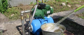
Using a centrifugal pump in gardening
Circulation pumps are used wherever liquids are used and ultra-high pressure or suction force is not required. For special applications, other types of devices are used - vibration, rotary, piston or induction.
Frame
It is made in the shape of a spiral with a decreasing radius, similar to a snail shell. The cavity of this body does not remain the same throughout. The flow area increases as you approach the pressure pipe.
Where the volute casing ends and the discharge pipe begins there is a protruding wedge called a cutwater .
It physically separates the volute housing from the discharge port and ensures that fluid leaves the pump rather than simply spinning around in the volute housing.
The flared part of the volute casing is very important, because with the help of it the pump creates pressure.
Pump repair and maintenance
Before purchasing a repair kit for pump inspection, pay attention to the design of the seal and the size of the shaft rotation bearings, since the dimensions of the parts differ depending on the year of manufacture of the pump. Types of repair kits for water pump MTZ 80
Types of repair kits for water pump MTZ 80
Dismantling the unit
The inconvenience of the process of dismantling the pump lies in the narrow distance between the block and the radiator of the MTZ 80 tractor. The success of quick disconnection depends on the availability of an arsenal of socket wrenches and wrenches for them that correspond to the design features of the location of the unit, as well as the professionalism of the mechanic.
To disconnect a node from a block, perform operations in the following sequence:
- Raise the tractor hood
- Loosen the tension and mounting bracket of the generator
- Remove the drive belt
- Unscrew the radiator diffuser
- Disconnect the pipes from the pump
- Loosen the three bolts securing the pump to the block and remove the assembly.
Disassembling the pump
The presence of bench saws for fixing and a screw puller for pressing off the pulley hub and shaft with bearings will ensure quick and comfortable disassembly of the unit.
The pump is disassembled in the following order:
- Loosen the fastening bolt and remove the impeller with seals from the shaft
- Unscrew the fastening bolts on the hub of the drive pulley, disconnecting the fan
- The central nut securing the pulley to the shaft is unscrewed
- Having fixed the pump body in the cleats, using a screw puller or by gently striking the circumference of the inner rim of the pulley, remove the part from the shaft key connection
- Dismantle the retaining ring securing the shaft with bearings in the housing bore
- Press out the shaft with bearings using a screw puller or by carefully striking the end of the shaft from the impeller side, having first screwed the fastening bolt into the shaft so as not to spill the end of the part with the internal thread.
Pressing out the pump shaft
After disassembling, clean the housing and impeller from dirt and scale
Particular attention is paid to the contact surfaces of seals and gaskets. Using sandpaper, scale deposits and small shells on the contact surfaces with seals are cleaned, especially in the pump housing around the shaft hole
Removing the pulley and retaining ring
If large potholes or cavities are identified that cannot be cleaned, the unit body must be replaced. A shaft with unacceptable wear in the bearings, bearings with axial play in the cages are also replaced. To achieve a positive result when eliminating pump leaks, reusing seals and seals is unacceptable.
Assembly and installation
The assembly process is carried out in reverse order. All pump parts must take their places. The result of correct assembly is free rotation of the impeller by hand without distortions or snags on the body, without axial play in the shaft and impeller seats. The crucial point in assembling the unit is the landing of the pulley hub on the shaft key
When pressing the part onto the shaft, it is important not to displace the key from the landing groove and ensure a reliable connection without radial and axial play. Connection is carried out with the contact surfaces of the block and pump thoroughly cleaned through a new gasket
For a comfortable future inspection of the unit, experienced tractor drivers install a similar part made of brass instead of the standard impeller fastening bolt, thus preventing the formation of corrosion, which makes disassembly difficult.
Service
Pump maintenance operations include monitoring the drive belt tension and timely lubrication of the unit bearings. Regular lubrication is carried out by injection through a grease fitting during maintenance 1. The belt tension is changed by the position of the generator when the mounting bracket is rotated.
The correct tension ensures the belt moves with minimal slippage and is controlled by the deflection of the middle of the large drive branch “alternator pulley - crankshaft pulley” when pressed with a force of 30...50 N by 10...15 mm. Control is carried out every 60 hours of operation. When putting a new engine into operation, the tension is checked no later than after 2 to 3 work shifts. Excessive tension increases the load on the drive unit support bearings and accelerates their wear.
Working wheel
There are 3 types of impellers:
- open,
- semi-closed
- closed
The simplest design is the open wheel, which consists of razor-sharp blades evenly spaced on a hub.
Open wheel
The large, unrestricted fluid supply allows this type of wheel to transport fluids containing dirt, dust, sediment, and solids , making them ideal for waste pumps.
It is used in water treatment plants where wastewater is pumped to treat coarse sludge with solid impurities. Therefore, it has cutting blades at the front of the wheel to cut very large impurities.
If the blades are placed on the back plate, then such a wheel is called semi-closed .
Semi-closed wheel
If the blades are between two plates, then it is called closed .
Closed wheel
Closed wheels are more efficient than semi-closed and open wheels. Because the fluid flow follows a strictly defined path. This means that more fluid comes out of the pump and less simply circulates inside the wheel.
Their disadvantage is that they can easily become contaminated with debris.
A very popular misconception is that swirling blades help push fluid. But that's not really what they're designed for.
The purpose of the blades is to guide the liquid along the smoothest path. Backward-twisted blades help stabilize fluid flow conditions at high speeds and reduce engine load.
By the way, read this article too: Types and design of bearings
The correct direction of rotation for this wheel is counterclockwise . Therefore, by the direction of the bends of the blades, we can tell the direction of movement of the wheel.
How to independently diagnose problems and fix them?
This section describes the most common pump performance problems and how to correct them.
When does cavitation occur and how to get rid of it?
- The ventilation pipe is clogged or its diameter is too small. In this case, it is worth cleaning or buying a wider pipe and replacing it.
- Air or gas particles have entered the liquid. In case of this problem, it is necessary to completely immerse the pump in water or install special fender flaps.
- The pipeline is clogged or slagged. To fix the problem, you need to clean it and the hydraulic section.
- Excessively high pumping temperature - find another pump.
What is the reason for the lack of power?
- The pump is rotating in the wrong direction. In this case, it is necessary to swap the phases.
Attention! This only applies to three-phase pumps.
- Wheel wear or damage. It is necessary to replace a broken or unusable part.
- If the pump line or wheel is clogged, then you need to clean them;
- The check valve is clogged - just filter it;
- The valve may be leaking. Then you need to close it tightly.
- The ventilation is clogged. Inspect and clean if necessary.
In what cases does the control device indicate Overload?
- The mains voltage has dropped. In this case, check the voltage.
- High fluid density overworks the motor. It is necessary to change the motor or install a smaller wheel.
- Increase in device temperature. If this happens, then it is immediately necessary to reduce the generation using shut-off valves.
- If one phase has failed, then you need to check the contacts and change the fuses if necessary.
Why does the check valve make noise and how to deal with it?
There can be one reason for this - the valve closes very slowly and can hit. In this case, it is necessary to change it to a quick-closing one.
If the equipment itself is loud, how can you solve the noise nuisance?
- Inappropriate wheel alignment. In this case, we change the cable's power cores.
- Damage to the impeller. The solution would be to change the spare part.
- The machine or ventilation line is clogged. In case of any contamination, we clean it.
- Low liquid level in the tank. Then we check the level and, if necessary, reconfigure the device.
- The noise may be caused by swaying pipelines. We check the elasticity of the connections and secure them tightly using pipe anchors.
Conclusion: this section was created to control the correct operation of water pumps. If you take proper care of it and can fix it yourself, and at the first signal, breakdowns, your pumps will serve you efficiently and reliably for decades.
Shaft and bearings
Whatever type of wheel is used, it is mounted on a rotating shaft. The shaft must be secured in the housing with bearings in one of 2 ways:
- Console
- Symmetrical
Cantilever fastening
When the shaft is cantilevered, the impeller is fixed at one end and the bearings at the other.
This design places the suction and discharge ports perpendicular to each other, and the suction port directly in front of the center of the wheel.
Such pumps are called end suction pumps. They are widely used because they are cheap and easy to produce, but they have one drawback related to the path of fluid movement.
During pump operation, a low pressure zone is created in the suction port.
There is a high-pressure zone at the outlet of the wheel, from which the energized fluid enters the spiral casing.
Fluid flows towards the rear plate in open and semi-open wheels, which completely destroys the pressure balance. As a result, an axial force or load occurs - pushing the wheel towards the suction hole.
This can be compensated for by installing stronger bearings or drilling holes in the wheel plate to equalize the pressures. But these are not effective methods.
Symmetrical mounting
A more effective solution is to place the shaft on bearings on both sides. This is called symmetrical design .
Shaft support is improved not only by the placement of bearings on both sides, but also by the ability to use symmetrical closed wheels with double suction.
Since there are the same high and low pressure zones on both sides of the wheel, this successfully eliminates loading forces due to the balance of pressures. This design also has another advantage. The suction and discharge ports are located parallel to each other on opposite sides of the pump, and the housing is axially divided.
By simply unscrewing the bolts and removing the cover, the service technician can access the rotating part of the pump inside without removing the entire pump from the system.
Due to the separate axial design, pumps with a symmetrical bearing arrangement are called split-casing .
All of these, of course, are very good reasons to install such a pump in your mine right now. But there are some disadvantages. Because maintenance operations and sealing requirements are more complex for split casing pumps than for end suction pumps. They are also more expensive.
By the way, read this article too: Positive displacement pumps: classification and principle of operation
Centrifugal and vibration
Centrifugal pumps are more suitable for home use, since their operation scheme is simpler and more efficient. Its design includes a shaft on which the blades are located. In this case, all the pressure force is concentrated at the edges of the blades. But to use this equipment, it is necessary to install a filter, because it does not react well enough to pollution and loses power because of it.
Knowing well the purpose and design of a centrifugal water pump, you can choose the appropriate model. You can check the availability of additional components in the design with the seller.
Vibrating ones do not lose effectiveness due to poor-quality and sand-contaminated water, but constant vibrations lead to silting of the source. As a result, the performance of these devices is less than that of vortex devices.
Shaft location
Centrifugal pumps are usually located horizontally . But sometimes vertically .
Vertical pumps are used to reduce installation space. You can find them at the bottom of a well or well, connected by a long, long shaft with a motor on top. This brings us to the motor connection. Usually electric.
How does a heat pump work?
The operation of a heat pump is based on a unique Carnot cycle, with its own circular process. According to this scheme, the heat pump is capable of pumping in a circle the dissipated heat taken from the ground, water or air.
This approach makes it possible to collect almost 75% of the thermal energy by the heat pump, but 25% of the energy is required to operate the equipment itself. For this reason, a heat pump cannot do without the consumption of electricity, which is necessary for its efficient operation. At the same time, consuming only 1 kW of electricity, the heat pump is capable of delivering 5-7 times more.
The operating principle of a heat pump is very similar to a regular refrigerator or air conditioner that we are used to using every day. For example, deep underground (below the freezing level of the ground) or at the bottom of a reservoir, pipes are laid according to the scheme of heated floors, through which the coolant circulates all the time.
The temperature underground, at the depth of which the pipes are laid, is always constant, with a positive mark. Therefore, the coolant does not heat up too much, only by a few degrees. Then, once it enters the heat pump's evaporator, it releases the collected heat to the internal circuit, and this is where the fun begins.
In the internal circuit of the heat pump there is freon (refrigerant), which enters the evaporator under high pressure and takes away part of the heat given off by the coolant to the walls of the evaporator. The refrigerant then enters the heat pump's compressor, where it is compressed, heated, and pushed into the condenser.
Already in the heat pump condenser, heat is taken directly into the heating or hot water supply system of the house (via a heat exchanger). The heat transfer cycle then repeats over and over again, which is how a heat pump works.
Types of heat pumps
Today, there are different types of heat pumps, for example, ground-water or air-to-air heat pumps. Let us briefly consider the existing types of heat pumps:
Ground-to-water heat pump: These are geothermal heat pumps that are designed to extract heat from the ground and transfer it into the house, passing it through the coolant that circulates in the heating system.
Water-to-water heat pump: heat, when using a water-to-water heat pump, is taken in this case from a well or well. To do this, a special hydraulic unit installed in the heat pump pumps groundwater, takes away heat and discharges it back into the well. This type of heat pump is notable for the fact that it is possible to use an existing well on the site in order to create geothermal heating in your home.
Air-to-water heat pump: the heat source in this type of heat pump is the surrounding air. Consuming only 1 kW of electricity, an air source heat pump can increase it to 5 kW for heating needs and hot water heating.
Air-to-air heat pump: The operating principle of an air-to-air heat pump is similar to that of a home air conditioner, which functions to heat rooms. The only difference is in operating efficiency, since air-to-air heat pumps are almost 3 times more efficient than any air conditioners with a heating function.
Of course, heat pumps, like other sources of alternative energy, have a future. When the oil and gas reserves on Earth are depleted, a reboot will be needed, and then the energy of the sun, earth and wind will come to the rescue, allowing all of humanity to survive.
Shaft connection type
There are 2 ways to transfer rotation from the motor to the pump: through a coupling or directly .
If the pump and motor are two separate machines, then they must be connected by a coupling.
Coupling connection
Couplings come in different shapes, sizes and designs. And one common requirement for them is to ensure the correct integrity of the shafts, otherwise without them, ensuring integrity would be a very sophisticated process.
To facilitate and maintain integrity, the engine and pump are mounted on a common support - a base plate.
Or, in the case of vertical installations, the engine is located on the frame.
This type of connection between the motor and the pump is called coupling. For large powerful installations and pumps with a dismountable casing, connection via a coupling is the only possible option.
The second connection method is direct. The engine and pump are located on a common shaft with a wheel located in a cantilever on the other side of the engine shaft. In this case, the installation does not require a coupling or complex procedures to maintain integrity.
However, because the motor and pump are located on the same shaft, supported only by the motor bearings, this method is only suitable for small and medium-sized end suction pumps.
Pump material design
The versatility of the design of centrifugal units predetermines the widespread use of installations. The equipment is used for pumping purified water, petroleum products and liquids mixed with aggressive or abrasive substances. For the manufacture of housings and rotors, materials are used that are resistant to the effects of the reagents for which the pump is designed. Additionally, operating conditions and the duration of continuous work cycles are taken into account.
Metal version
Standard devices used for pumping water and aqueous solutions are equipped with bodies made of gray cast iron. Stainless steel and non-ferrous metals (for bearing supports) are used in the design of the units; the rotors are made of cast iron or carbon steel. Rarely, installations made of titanium alloys are used.
Lined and plastic versions
If the pump is used to pump aggressive substances (for example, acids or alkalis), the metal components are destroyed due to corrosion. The use of stainless or special steels reduces the degree of wear, but leads to an increase in the cost of the structure. In this case, it is advisable to use components made of plastic or composites. The type of material used for the production of parts is indicated in the technical documentation (for example, polyvinyl chloride is designated as PVC).
There is equipment with housings made of plastic, which undergoes additional mechanical processing. But due to reduced mechanical strength, a similar design is used for small-sized installations. Industrial acid pumps are made of metal that is lined with a layer of polymer material that prevents corrosion. When manufacturing parts, it is important to ensure adhesion of dissimilar substances and avoid cracks through which aggressive solutions will penetrate under the plastic layer.
O-ring materials
Depending on what the pump is planned to be used for, different materials are used for the sealing elements. The most common parts are made from ethylene-propylene-based rubber (code EPDM) and nitrile-butadiene rubber (NBR). Fluorinated rubber (Viton or FPM) or perfluorinated type material is used in loaded installations for pumping liquids with abrasive suspension.
Number of steps
A pump is classified by the number of stages it has. Most pumps have one stage with one impeller and one volute casing. However, some pumps have additional stages connected in series to increase pressure.
Multistage pump rotor
The idea is that one wheel imparts energy to the fluid and then directs it to the next wheel, which adds more energy to the fluid and then directs it to the next wheel, and so on, until eventually the fluid enters the discharge pipe.
Centrifugal pump installation technology
Let us dwell on the principle of installing centrifugal pumps for water supply.
The principle of their installation is similar to other types.
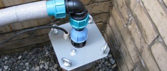
- Deep units are fully connected to all communications, attached to a cable and placed directly into the reservoir. Don't forget to install the float switch the day before. There is no difficulty in installing deep-well pumps, but it is a labor-intensive job that takes a lot of time.
- Surface-type units are placed near a reservoir. You must first take care of arranging its protection from unfavorable climatic conditions. This device will not be able to withstand sudden temperature changes, especially in winter. Similar to the deep unit, the surface pump is pre-installed with all communications, and then a hose with a check valve is connected to it, the second end of which is immersed in the reservoir. Then the chamber is manually filled, this is done once at the start of work, and the pump is started.
As you can see, all the installation and maintenance work on water supply units is not complicated. As for the choice of product based on the principle of its operation and other characteristics, the choice remains with consumers.
You may also like
What are the types of water centrifugal pumps?
Choosing a centrifugal pump for a well
Pumps: history and principle of operation of different types of pumping units
Today we will try to tell you what a pump is, the operating principle of different types of pumping units, how they are driven, and what functions they perform.
Some people who have used or are using pumping units do not always understand the principle of operation of the unit, they only know what task this pump solves. In this article we will try to explain the operating principle of certain pumps. And this will not just satisfy curiosity. If you are faced with the need for a pumping unit, you will already be “savvy” to select the right pump.
First a little history...
The first methods of pumping water have been known since very distant times. Water was scooped up with ladles or other containers. It was physically difficult to ensure the volume and speed of water supply while extracting liquid from a reservoir. The first thing our ancestors came up with was a scooping wheel. According to archaeological sources, it was a device in the form of a wheel with spokes, at the end of which, at the junction of the rim and the spokes, buckets were attached. The lower vessel was placed in water. When the wheel began to rotate around its axis, the buckets scooped up water from the reservoir, and then at the highest point of the wheel, with a lifting height equal to the diameter of the wheel, the water poured out of the buckets into a gutter located on the side, with a certain length and slope (gravity flow), so to speak, up to consumer. The wheel was rotated by physical force with the help of bulls, oxen, or simply with hands. The bucket hung to one side, making it difficult for the wheel to rotate, which also led to water loss. A design based on using the empty space between the outer and inner rims of the wheel, where there were holes on the side for drawing water, helped to get rid of losses. This reduced water loss during pouring, since the speed of rotation of the scoop wheel was constant. Already from the third century BC. Water pressure was used as the rotational force of the wheel in water scooping systems. Below we will show the most common options for extracting and supplying water that our distant ancestors came up with.
The first picture shows a wheel with “manual drive” (containers in the wheel rim).
In the second picture, the “foot drive” was driven by a person stepping from one crossbar to another, and the drawing vessels were already on the side.
The third picture is the most “progressive” solution of that time - a self-propelled wheel with spoon-shaped blades. A wheel with spoon-shaped blades rotates the lower drum, which, in turn, is rigidly connected by a chain to the upper drum. Buckets were fastened on a chain; when moving upward, they were filled with water, which poured into the gutter, located at the top point of the structure. Thus, the buckets were lowered down, already empty, in order to scoop up water from the river again.
The next step in the civilizational spiral of “pump building” development was the so-called “Archimedes screw”
Archimedes is an ancient Greek scientist-thinker, known about him from the works of ancient historians, who invented a screw water-lifting device, later named in his honor. This device was an inclined wooden pipe with a screw installed inside. The propeller rotated using a wind wheel or manually. As the lower end of the screw turns, it collects a certain amount of water. This amount of water will slide up the pipe as the shaft rotates until finally the water flows out of the top of the pipe. However, losses were inevitable, since some amount of water flowed back, i.e. efficiency left much to be desired. The greater the screw angle, the greater the feed height, while reducing productivity. By the way, for example, this type of construction was used to drain the flooded holds of ships and mines.
The next type of pump invented is piston pumps.
The piston pump is the brainchild of the Greek inventor Ctesibius of Alexandria, who lived in the 3rd century BC. e. Piston pumps were used to lift water from wells. The operation of such pumps is based on the basic principles of pneumatics and hydraulics. By the way, he also invented a prototype of such a musical instrument as an organ, using two piston pumps. The sounds extracted from this instrument were surprisingly very “clean”. It is generally accepted that these pumps are pioneers in the history of mankind, since the layout of the device has been determined for a long time to come, right up to the present day. There was a transition to replacing the construction material from wood to bronze. But the basic elements of the device are the same as in modern pumps: plunger, cylinders, valves.
The advent of the steam engine and hydraulic drives prompted a technical revolution in industry. In 1712, English inventor Thomas Newcomen created a steam-driven piston pump for pumping water. In modern times, piston pumps are still used to lift water from wells and wells.
Bellows pump
Bellows pumps are a bellows type of vertical accordion, which is compressed to pump liquid. The simplest pump design consists of only a few parts, which are usually made of plastic, so they are not subject to corrosion. They are used for pumping out liquids, including aggressive ones, from barrels, bottles, canisters, etc.
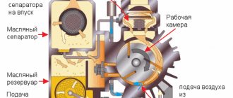
Rotary vane pump
Rotary vane pumps are self-priming positive displacement pumps - the movement of liquid occurs due to a change in volume in the working chamber of the pump. Used for pumping viscous liquids and oils.
The design of the pump is an eccentrically located rotor having longitudinal radial grooves in which flat plates slide, they come out of the grooves and are pressed against the cylindrical surface of the housing bore. As a result, the pumped viscous liquid fills the space between the plates and is then pushed into the discharge pipe. Rotary vane pumps are widely used in various fields where vacuum oil is used in the operating process.
Gear pump
Gear pumps are a device so simple that it once again confirms the genius in the very simplicity of the invention. Gear pumps are designed for pumping viscous, oily media. The unit consists of gears interlocked with each other, which are driven under a forced change in the cavity between the gears. The drive gear is in constant engagement with the driven gear and sets it in motion, rotating it in the opposite direction. The liquid enters the cavities between the teeth, moves along the wall of the pump from the inside and is pushed out through the outlet pipe into the pipeline.
Impeller pump
Impeller pumps (vane pumps, soft rotor pumps) are a subtype of rotary vane pumps. Thanks to their special design, pumps with a flexible impeller (impeller) allow you to carefully and efficiently pump certain media with different viscosities and densities. The working part of the pump is a soft impeller made of elastomer. The rotor axis is located eccentrically to the housing. The rotor rotates, the blades bend and straighten, create a vacuum and suck in the medium. The movement of the blades transfers the medium to the outlet of the pump pump.
Sine (sinusoidal) pump
The most important design element of a sine wave pump is the rotor, which is shaped with a sinusoidal structure (hence the name of the entire device). Sine-wave pumps have four chambers that open and close in turn, allowing you to pump even very delicate structures, such as crushed tomatoes.
The pump's design provides high suction power, but unlike traditional pumps that have an impeller that "cuts" the fluid being conveyed, a sine impeller gently pushes the fluid through the pump. The maximum permissible size of pumped particles depends on the volume of the cavity between the disk and the pump body.
The pump has no valves. The design of the pump is very simple, which guarantees long and trouble-free operation of the device.
Screw pump
Positive displacement screw pumping units are designed for pumping liquid media with high viscosity; pumping liquids with the inclusion of solid fractions is permissible. Thanks to their design features, screw pumps perfectly suck and pump liquids of various viscosities and consistencies. The pumped liquids are not subject to centrifugal or pulsating forces, thanks to which screw pumps very carefully pump even the most sensitive media. A condition for proper pump operation is the selection of the appropriate speed for the given medium. Screw pumps are highly reliable, they are economical and easy to operate, and have high maintainability.
Advantages of screw pumps:
- simplicity of design, good maintainability
- high suction power
- fluids are not subject to centrifugal or pulsating forces, so there is no need to use pulsation dampers or compensators in pipelines
- Possibility of pumping liquids containing solids
- wide range of applications for feed due to the possibility of changing it by changing the rotation speed
Screw pumps are widely used in the petrochemical and food industries.
Peristaltic (hose) pump
Peristaltic pumps are often called linear or peristaltic pumps. The first patent protecting the invention was filed in the late 19th century in the United States, and the device was originally intended for blood transfusion during surgery. Transport of liquid using a peristaltic pump is possible due to the movement of rollers or shoes sliding along the hose. These pumps allow fluid to be pumped without contamination while maintaining relatively low operating costs. Due to these characteristics, peristaltic pump-based metering pumps play a huge role in various industrial and medical fields. The principle of operation here is simple - it involves moving a medium located in a special thick-walled hose. This is possible thanks to a rotating head with rollers (shoes) that compress the drain hose located around the circumference inside the housing; the rollers push the liquid to the pump outlet.
Vortex pump
Vortex pumps, for the most part, are designed for pumping liquids, but can also be used for pumping gaseous media; the movement of the liquid in it is carried out due to the forces of inertia and friction. There are several subtypes of vortex pumps, but all have a similar component - an impeller in the form of a steel disk, where there are pits on the outer diameter that form blades of various types. The wheel with blades rotates inside a cylinder-shaped housing, while the distance from the end of the blade to the wall is minimal. The principle of operation of a vortex pump is that water is sucked into the inlet and swirled into a vortex thanks to the impeller. With low energy consumption, the flow power increases many times, and the liquid with high pressure is ejected from the outlet pipe. The big advantage of vortex pumps is the ability to work with small volumes of liquid, while the pumps can provide a fairly strong pressure. Taking into account the above-described features, vortex pumps have found application in systems where there is a need to create high pressure with a relatively small flow. For example, in small automatic water supply pumping stations. The ability to pump a liquid-gas mixture makes it possible to operate vortex pumps for pumping volatile liquids (gasoline, kerosene, etc.), which is the basis for the use of such pumps in fuel filling systems.
Gas lift pump
Gas lift pumps are one of the methods for forcibly lifting a droplet liquid using the energy contained in the compressed gas mixed with it. Most often, they are used in the extraction of petroleum products. The operating principle of a gas lift is to inject gas under pressure through the annular space between the outer and inner pipes. Gas reduces the pressure drop in the tubing, thereby facilitating the displacement of oil products through the wellbore to the surface using natural energy.
Diaphragm (diaphragm) pumps
The diaphragm pump is one of the most versatile types of pumps due to its ease of operation as well as its relatively low failure rate. Diaphragm pumps belong to the family of positive displacement pumps, in most cases they are driven by compressed air, less often by an electric motor.
The principle of operation of diaphragm pumps is as follows: compressed air penetrating one of the diaphragms causes it to compress and push liquid into the outlet hole. At this time, the second diaphragm, on the contrary, creates a vacuum, sucking in liquid. After passing the pulse, the pneumatic coaxial exchanger changes the direction of compressed air behind the second membrane and the process is repeated on the other side. The discharge pressure on the media side is equal to the pressure upstream of the diaphragm, so diaphragm pumps can operate with the outlet valve closed without compromising diaphragm life. Diaphragm pumps require no cooling or lubrication during operation, allowing trouble-free, dry operation.
Screw (axial diagonal pump)
Screw (axial-diagonal pump) is a screw-type submersible pumping equipment. Pumping a liquid medium with a screw pump is based on the operation of a specific Archimedean screw of a certain length. An exceptional advantage of this unit is the ability to pump liquids with heavy contamination (small abrasive substances).
Centrifugal pumps have good suction capacity and higher performance compared to other types of vane pumps. They are used for pumping oil sludge, fuel oil, diesel fuel, etc.
Centrifugal pump
The pump design consists of a volute casing and an impeller with blades installed inside, rotating at a constant speed. The fluid constantly flowing through the impeller is subject to centrifugal force. Thus, the engine energy is transferred to the fluid through the impeller, resulting in increased pressure and kinetic energy. Once the fluid leaves the rotor, its kinetic energy is further converted into pressure energy. The increase in kinetic energy and pressure in the pump depends on the design of the rotor and its rotation speed. Centrifugal pumps are ideal for filling containers and filling swimming pools, supplying water to private houses, cottages and irrigating household plots.
Multi-section pump
Centrifugal pumps equipped with two or more impellers placed in series are called multi-section; in fact, this is a series of centrifugal pumps placed in series. This design of the equipment makes it possible to create significant pressure at the outlet: having left the first impeller under pressure, the liquid enters the second impeller, where in turn the pressure also increases, then to the third, etc.
Multi-section pumps are mainly used in cold and hot water supply systems. They can also be used in other areas of industry and economy, and civil facilities.
Jet pumps
Jet pumps come in two main types:
- Ejector - a pump that sucks out the medium and creates a vacuum
- Injector – pumps that inject a medium under pressure.
The job of a jet pump is to create a pressure difference between the pressure in the suction tank and the pressure in the discharge chamber.
The working fluid supplied by the feed pump through the inlet enters the nozzle, where the speed of the fluid increases due to the pressure drop, according to Bernoulli's law. The pressure drop in the suction chamber is sufficient to lift liquid or slurry from the suction tank.
The advantage of jet pumps is the absence of moving parts and, therefore, high reliability. The disadvantage is low energy efficiency (30 - 40%). To operate the pump, a compressed air or steam supply is required.
Hydraulic ram pump
The hydraulic ram pumps water without gasoline, current or gas; it does not require a power source and, in the absence of an engine, is capable of lifting liquid to a height of several tens of meters. Such a pump can operate continuously for a long time, providing water to eco-villages, village houses, agricultural land, etc. The principle of operation of a hydraulic ram is to use the energy of a hydraulic shock.
The hydraulic ram receives energy directly from running water, flowing under the influence of gravity through a pressure pipeline into a drain, which is located at a lower level.
By passing most of the water through itself from a small height h (the height difference between the drain and the water level in the supply tank), the hydraulic ram lifts a smaller part of the water to a large height H (the height difference between the top point of the outlet pipe and the water level in the supply tank).
This is a fairly low energy efficiency device because only a small portion of the energy flowing through the water pipe is converted into work to lift water into the reservoir.
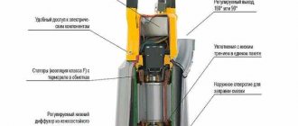
Scroll Vacuum Pump
Vacuum pumps create vacuum using a simple mechanism consisting of two spiral parts that overlap each other. One part is the pump stator and remains stationary, the other part is the rotor and rotates eccentrically, creating moving zones of trapped gas.
When the pumped gas enters the volute mechanism, it is then moved around the periphery, compressed and directed to the pump outlet. Dry scroll vacuum pumps are extremely reliable.
Laminar pump
A laminar (disc) pump is a type of centrifugal pump, but can perform the work not only of centrifugal pumps, but also of progressive cavity pumps, vane and gear pumps, i.e. pump viscous liquids.
The impeller of a laminar pump consists of two or more parallel disks. The greater the distance between the discs, the more viscous the liquid the pump can pump. Theory of the physics of the process: under laminar flow conditions, layers of liquid move at different speeds through a pipe: the layer closest to the stationary pipe (the so-called boundary layer) flows more slowly than the deeper (close to the center of the pipe) layers of the flowing medium.
Similarly, when fluid enters a disc pump, a boundary layer forms on the rotating surfaces of the parallel impeller disks. As the disks rotate, energy is transferred to successive layers of molecules in the fluid between the disks, creating velocity and pressure gradients across the width of the orifice. This combination of boundary layer and viscous drag results in a pumping torque that "pulls" the product through the pump in a smooth, almost pulsating flow.