26.03.2020
- Technological aspects of the process
- Types of chips during turning
- Selection of cutting tools used for turning metal parts on machine tools
- How the equipment works
- Main types of work, what operations can be performed
- What type of tools are needed for parts that are made on lathes?
- Scheme of processing on a lathe
Metal turning on a machine is one of the most popular methods, with which you can, for example, create a shaft or other part of cylindrical or conical shape. In the article we will talk in more detail about the features, types and all the nuances.
Technological aspects of the process
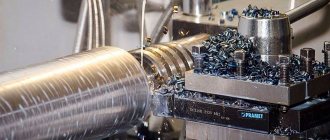
The essence of the procedure is the sequential removal of the top layer from a rotating workpiece using cutters and other tools. This produces chips, which can be more or less coarse depending on the material and feed rate, and also have a different shade - the color change occurs due to heating due to friction and oxidation.
The operator secures the product on both sides in the spindles. One of them has free rotation, that is, in fact, it is only responsible for reliable fixation, while the second is the leader. Movement is transmitted through it, and speed is also regulated.
Once the workpiece is secured, the cutting process on lathes begins. First you need to choose the right speed mode. On professional equipment, the power is quite high, but you cannot always work at maximum. For example, if the shaft is very long, then its vibrations and errors will only increase with increasing speed, which will lead to inaccuracies. The second reason to choose a mode is the type of processing, namely, roughing, roughing, semi-finishing, finishing or fine. Ideally, one part should go through all of these stages with varying feed selections as well as different cutting tools for lathes and metalworking.
When the main indicators are selected, you can proceed to installing the cutter. It can be made of different types of alloy, but it must be:
- more durable than the workpiece material and less brittle;
- always well sharpened.
Special cutting edges are used for different tasks. They are installed in a caliper that has reliable clamps, as well as an adjustable angle of rotation and tilt, that is, all the parameters for the most accurate metalworking.
Now you can start turning on the installation. The whole operation consists of correctly selected two movements:
- tool feed;
- shaft rotation.
The first movement is made by the support. It moves horizontally and vertically, and if there are runners, it can move diagonally for turning cones. This is how operations such as turning and drilling are carried out on a lathe. However, for the latter type of task, the tool (drill) must be able to rotate, and the workpiece itself will be static. The movement of this part is determined either by automation or by handles and wheels. First, the operator sets it to the starting point, checks the depth, and then turns on the device and only adjusts the position of the cutter. The caliper speed is also adjusted depending on the type, material, and tasks.
The second movement is rotational. It is produced by the workpiece. The engine, which is responsible for the feed, is located in the front beam, and there are two of them. The force is transmitted to the spindle by means of belts. Rotation has a direction and speed, but no other parameters can be specified. The main thing for a turner is that there are minimal vibrations and errors, otherwise impacts on the tool will occur.
Since the machine operates mainly at high speeds, the essence of turning lies in the rapid removal of the top layer.
Problems that can be solved this way:
- Achieving specified dimensions with high accuracy.
- Drilling holes, reaming them and countersinking, cutting internal and external threads.
- The required surface roughness depends on the accuracy class.
- Cutting work - cutting part of the shaft, trimming edges.
- Grooving.
The cutting edge separates the integrity of the turning metal by applying friction and pressure to it. A break occurs at the molecular level.
Measuring machine parameters
Odometer
In addition to tools, there is a class of machines designed to determine the exact dimensions of parts and workpieces. This equipment is called coordinate measuring equipment. To complete the task, current dimensions are taken in three coordinates.
Structurally similar machines, or tables as they are also called, consist of a working surface on which the part is installed. The working heads have sensors for reading geometric parameters and change their position along three coordinates. Depending on the method of data collection, two methods are distinguished - contact and non-contact. In the first case, the information is read using a piezoelectric sensor-probe. The operation of the non-contact method is based on the return of a light signal from the surface of an object.
To select the optimal machine model, a comparative analysis of the following characteristics is done:
- error. The lowest rate is achieved with contactless data collection;
- desktop dimensions. The maximum permissible dimensions of the sample and the ability to work with several parts at the same time depend on this;
- maximum displacement of the working head relative to the desktop along three coordinate axes;
- minimum tool displacement step;
- type of software. It determines the ability to display graphic and text information in a form convenient for analysis. Also, using the software, the algorithm of equipment actions is programmed;
- overall dimensions and weight.
During the entire period of operation, it is necessary to follow the manufacturer's recommendations for servicing the machine. This directly affects the accuracy of measurements.
In addition to equipment parameters, environmental indicators such as air temperature and humidity should be taken into account during operation. This is especially true when using a non-contact method of data collection.
Types of chips
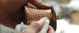
Waste generation is a natural process during metalworking. At the same time, some turners consider this a disadvantage, while others, economical ones, hand over all the waste for remelting, since the basic chemical properties are not impaired, and with the help of temperature it is possible to achieve steel standards during smelting. The third option is to simply take it to recycling centers.
When working manually, on standard machines, it is necessary to remove the chips in a timely manner so that they do not melt to the working surface and spoil the overall result. But on automated CNC equipment, which implements, there is a special chip removal function that guarantees the cleanliness of the process.
The shape of the waste can tell a lot about the work itself. There are four types of chips in turning.
Merged
It looks like long sections of a twisted spiral. If a thin layer is removed, then the turns are short with a small pitch, and if it is thick, then the spring will be more elastic, with sharp ends. It is usually produced when a soft alloy such as lead, tin or some types of steel is processed at high speed. Another condition for obtaining such a sample is that there are no significant defects, pits, or longitudinal grooves, that is, the shaft itself has already been pre-treated, including from rust, scale, and grinding work has been carried out on a lathe.
Merged is divided into tape and spiral. We wrote about the second in more detail above, but the tape comes out at a low speed of action on very ductile alloys.
Elemental
It breaks into short sections, moves away from the workpiece not smoothly, like the previous one, but in jerks, because at a certain moment it breaks, jumps out from under the tool, which is used to process parts on lathes for hard metals. There may be several reasons:
- low cutting speed, so a lot of material is taken at once, it does not have time to move away quickly;
- there are obstacles on the path of the cutter, for example, strong graininess of steel, there is no soft homogeneous structure;
- the sample is made of a very durable metal, cast iron, which has high hardness, but also considerable fragility, that is, instead of smoothly stretching, the chips immediately break;
- incorrect work of an inexperienced turner - incorrect choice of speed, mode.
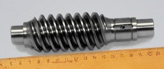
Broken
These are very small pieces that fly away from the cutting zone. You should not be afraid of them; this is a natural result when cast iron or bronze workpieces are processed on lathes. The fact is that cast iron and bronze have low ductility, so instead of bending, the top layer simply splits and crumbles. The main thing here is not to remove excess, move the cutter at a shallow depth and it is better to make 3-4 passes than one, but deep, since the last action can lead to the formation of cracks in the thickness of the metal.
Let's look at the image, we see the break in the last picture:
Stepped
Very interesting view. The Prireztsev part (the side close to the incisor) has a pronounced smoothness; it is all the more surprising that on the back there is a multi-tiered structure - the material is layered on top of each other, like steps on a staircase, hence the name. The steps, or notches, have the direction of individual elements connected to each other.
Typically, this type is formed when producing blank parts on a lathe at medium speed and low hardness.
All qualified turners take a separate course on chip formation. This branch of science studies plastic deformations that occur with friction, heat generation, cutting edge wear, changes in surface roughness and, of course, chip formation. The shape it will take depends on all the above processes.
The color depends on the material and mode used for turning. Usually, when processing steel, it comes out blue - this is normal, since heat is released during cutting, it goes into residues, which, under the influence of oxygen and temperature, oxidize, acquiring a blue tint. If you use a cooling emulsion during operation, you can get a yellow color. Orange and brown cuts indicate the presence of rust on the workpiece. With an even greater increase in temperature, the tint of tarnish is red, this is explained by the interference of white in films on the reflective surface.
Sometimes turners are frightened by dark blue, they think that there is overheating. Indeed, this indicates a significant increase in temperature, but it is impossible to say that this is bad, since the thermal sink works by taking away excess heat from the part. It is simply recommended to increase the coolant flow. However, its excessive use can lead to rapid wear of the incisors.
Selection of cutting tools used for turning metal parts on machine tools
When making edges, a material with high strength is taken, this can be:
- carbon steels – with high carbon content;
- alloyed - with additives in the form of chromium, nickel, copper, nitrogen;
- high-speed alloys;
- solids;
- mineral ceramics;
- artificial diamonds;
- synthetic materials (composites, hexomites).
The incisor is the most common type. It can be straight, right, left or bent. The second part is called the holder, it can have different shapes - rectangular, square or round. They are attached to the caliper using tacks and screws. It is very important to achieve a high degree of fixation for the strength of the turning material.
Depending on their purpose, all incisors are divided into:
- checkpoints;
- pruning;
- cutting;
- boring;
- groove;
- threaded;
- screw-cutting;
- shaped.
Accordingly, they perform different tasks - remove the top layer, trim the ends, grind grooves, make a through or blind hole. Also, the entire tool can be divided according to the type of work - some need to carry out boring, the second - rough processing of workpieces for subsequent finishing or thinning.
Cutting and measuring tools
Cutting tools for turning
When working on lathes, various cutting tools are used: cutters, drills, countersinks, reamers, taps, dies, shaped tools, etc.
Turning cutters are the most common tool; they are used for processing planes, cylindrical and shaped.
Turning cutters are classified according to the material of the cutting part, the nature of the operations, the shape of the blade, the direction of movement, and design.
Based on the material of the working part, there are steel cutters (with blades made of carbon, alloy or high-speed steel), carbide, ceramic, diamond, and CBN. Cutters made of carbon and alloy steel are currently practically not used.
Depending on the nature of the operations performed, cutters can be roughing or finishing. The geometric parameters of the cutting part of these cutters are such that they are adapted to work with large and small cross-sectional areas of the cut layer.
Based on the shape and location of the blade relative to the shaft, the incisors are divided into straight, bent, curved and retracted. With drawn cutters, the width of the blade is usually less than the width of the fastening part. The blade can be positioned symmetrically with respect to the axis of the cutter holder or be offset to the right or left.
According to the direction of feed movement, the cutters are divided into right and left. For right incisors, the main cutting edge is located on the side of the thumb of the right hand, if you place it on top of the incisor. In the working movement, such cutters move from right to left (from the tailstock to the front). For left incisors, with a similar application of the left hand, the main cutting edge is also located on the side of the thumb. Such cutters move from left to right in the feed movement.
According to the type of processing, they are divided into passing, scoring, cutting, slotting, boring, shaped, thread-cutting, etc.
- external grinding with a bent cutter,
- external grinding with a straight cutter,
- turning with cutting the ledge at right angles,
— turning the radius fillet,
— cutting external, internal and special threads
Measuring tools and devices for precise measurements
To tools and devices for precise measurements
These include single- or double-sided calipers, standard and angular tiles, micrometers for external measurements, internal micrometric gauges, micrometric depth gauges, indicators, profilometers, projectors, measuring microscopes, measuring machines, as well as various types of pneumatic and electrical instruments and auxiliary devices.
Measuring indicators
designed for comparative measurements by determining deviations from a given size. In combination with appropriate devices, indicators can be used for direct measurements.
Measuring indicators, which are mechanical pointer instruments, are widely used to measure diameters, lengths, to check geometric shape, concentricity, ovality, straightness, flatness, etc. In addition, indicators are often used as a component of instruments and devices for automatic control and sorting . The indicator scale division is usually 0.01 mm, in some cases - 0.002 mm. A variety of measuring indicators are minimeters and microcators.
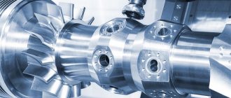
How the equipment works
There are two types of work - manual or automated. The operator performs all tasks manually - installs the workpiece, the cutter, carries out calculations, directs the support to the starting point, selects the rotation speed and feed mode, and also changes all these parameters during the process. In this case, you are dealing with a classic machine, created using old metal turning technology for boring.
The second type is modern CNC models. Such products are supplied by . The numerical control panel independently, automatically solves all the above tasks, excluding the installation of the blank, and even then, there is already equipment that has the function of fixing the workpiece. Such devices have high accuracy and ease of use.
The main types of work performed on lathes, what operations can be performed
- Finishing external cylindrical or conical surfaces is the main task of the turner. It involves removing the top layer to the desired size and creating roughness.
- Drilling, countersinking and reaming of holes.
- Trimming ends and ledges.
- Turning grooves and grooves.
- Cutting external and internal threads - with a screw cutter.
- Cutting off part of a part.
- Machining of internal cylindrical and conical surfaces.
- Chamfering surfaces.
- Rolling of corrugations.
These procedures are performed if additional equipment capabilities are available.
Types of measuring instruments
Main types of measuring instruments
To calculate the current parameters of a part, various devices and tools are used. Among them, the most commonly used are calipers, rulers of all types, bore gauges, micrometers, and calipers. To correctly select a specific model, you need to know the maximum and minimum sizes of the required quantities and the degree of error.
First of all, it is necessary to determine the measurement operations for a specific type of equipment. Most often, they are required for setting up critical components and parts - spindle heads, gearboxes and gears, moving mechanisms. At the same time, the tool is used to take parameters of parts undergoing the processing process.
Most often, the following types of tools are used to set up equipment and control the dimensions of parts:
- calipers. Designed for taking external and internal dimensions. Consists of a metal rod (ruler), frame and measuring jaws. Depending on the type of execution, it can be mechanical or electronic. The latter provides a high rate of measurement taking;
- bore gauge Necessary for determining the depth of grooves, calculating the height of ledges and other types of irregularities on the surface of a part or machine assembly. The most commonly used are indicator or micrometric models.
- calipers. With its help, the external dimensions of medium and large workpieces are taken;
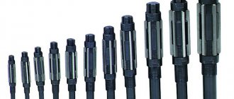
- odometer. Designed for measuring curved surfaces;
- level or spirit level. It has a wide range of applications - from construction to the manufacture of precision instruments. Necessary for checking the horizontal level.
In addition to these tools, it is worth noting rulers of various types. They can be installed on the machine's work table to increase processing accuracy.
In the design of vertical drilling equipment, the ruler is mounted directly into the front of the spindle head. It has a movable element connected to a drill chuck. This way you can control the drilling depth.
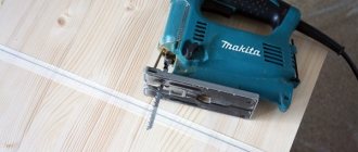
What type of tools are needed for parts that are made on lathes?
All tools can be divided into cutting and auxiliary. The carver works with the following devices:
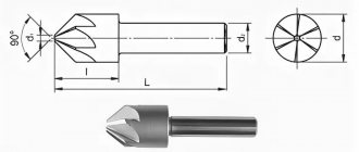
- Shaped cutter - the edge must coincide with the profile of the workpiece, represented by rolled rods.
- Centering drills - respectively, are necessary for drilling blind and through holes.
- Boring attachment – for boring cavities.
- Pass-through – suitable for roughing, semi-finishing and finishing of external and internal surfaces, for facing conical parts.
- Groove cutter.
- Cut-off.
- Carbide inserts are used in the manufacture of tool steel items.
The image shows the approximate set of each turner:
If you were interested in what tools are used to process parts on lathes, pay attention to the photo. Equipment should always be kept clean and sharpened.