Classification of cutting tools
Cutting tools are divided into blade
and
abrasive
.
Blade tool
– a cutting tool, with a given number of blades, of a prescribed shape.
Abrasive tool
Designed for abrasive processing.
By type of material being processed:
(
metal, wood
).
By shape
distinguished:
disk, cylindrical, conical and plate.
By design
,
according to the method of fastening the working part
:
solid, composite, prefabricated.
Solid cutting tool
- This is a cutting tool made from a single workpiece.
Composite –
cutting tool with permanent connection of its parts and elements
Prefabricated –
cutting tool with detachable connection of its parts and elements
By mounting method
–
tail and attachment
.
By type of drive
–
manual, machine and machine-manual
.
Types of cutting tools
Cutting tools are divided into the following groups:
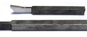
- For turning - it comes with shanks with a rectangular cross-section or has the form of boring bars manufactured according to the ISO standard. The fastenings are rigid, the accuracy of tool positioning on the machines is maximum.
- For milling - a metal-cutting tool with a set of teeth. It removes chips from workpieces, allowing you to obtain parts of the desired design. The main movements during cutting are rotation of the cutters around their own axis, additional movements are feeding the workpiece to the cutter.
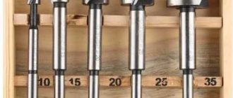
- For drilling - a group of devices that are used to make holes in panels, large tenons, and bolts.
All types of parts must be strong, durable, made of hard alloys.
Classification of blade tools
According to the material of the working part
They are distinguished
by steel, high-speed cutting, carbide, mineral-ceramic and super-hard materials.
By number of blades:
single-
and
multi-blade tool.
Multi-blade tool
– the blades in space are located in the direction of the main movement sequentially.
According to the location of the teeth in space:
peripheral, end, peripheral-end.
According to the design of the blades:
Mechanical blades
– a prefabricated blade tool with a detachable connection to the body or knife.
With brazed plate
– a bladed tool, the blades of which are made by soldering a cutting plate onto a body or knife.
With glued plate
– connection with glue.
Fused Blade Tool
- a composite blade tool, the blades of which are made by surfacing tool material.
Tooth direction
–
straight, helical and helical.
Types of Blade Tools
Cutter
– single-edge tool for processing with translational or rotary main movement and the ability to feed in any direction
Milling cutter
– a blade tool for processing with a rotary main cutting movement of the tool without the possibility of changing the radius of the trajectory of this movement and with at least one feed movement, the direction of which does not coincide with the axis of rotation
Axial cutting tool
– blade tool for processing with a rotary main cutting movement and a feed movement along the axis of the main cutting movement
Drill
– an axial cutting tool for creating a hole in a solid material and/or increasing the diameter of the hole.
Countersink
- axial cutting tool to improve the accuracy of the surface shape and increase its diameter.
Scan
- axial cutting tool to improve the accuracy of the shape and size of the hole and reduce surface roughness.
Countersink
— axial multi-blade tool for processing the conical entrance section of the hole.
Countering
— axial multi-blade tool for processing the cylindrical and end sections of the workpiece.
Tap
— axial multi-blade tool for processing internal threads.
Die
— axial multi-blade tool for processing external threads.
Broach
- a multi-blade tool with a number of successively protruding blades one above the other in a direction perpendicular to the direction of the speed of the main movement, intended for processing with translational or rotational and no feed movement.
Shever
- a multi-blade tool in the form of a gear or neck with a blade on the side surfaces of its teeth for processing the side surfaces of the teeth, which uses relative sliding between the teeth of the tool and the workpiece.
Combination cutting tool
– a blade tool that is a combination of blade tools of different types with a common fastening part.
Rotary cutting tool
- a prefabricated blade tool, the round blade of which performs a rotational tangential cutting movement.
Profile blade tool
– a blade tool whose cutting edge shape is determined by the shape of the machined surface, shaped and rolled.
Shaped
– the cutting edge of which forms the profile of the processed surface simultaneously with all points of the edge.
Rolling blade tool
– the cutting edge of which, during processing, forms a profile of the machined surface as an envelope of successive positions of the cutting edge relative to the workpiece.
Blade tools
Contents
Introduction. 2
1. Expanding the technological capabilities of gear processing methods 4
2. Processing methods with blade tools... 7
References.. 19
Introduction
In the designs of many machines, instruments and units, gears are most widely used as transmission mechanisms. This is due to a number of their advantages compared to other types of gears, including: the ability to transmit the highest torques, ensuring a constant gear ratio, high gear efficiency, small dimensions when transmitting high torques, smooth and quiet operation, etc.
The advantages of gears are largely determined by the accuracy of the parameters, the quality of the working surfaces of the teeth and the mechanical properties of the material of the gears.
In connection with modern trends in the development of technology, the requirements for the accuracy of parameters and mechanical properties of gears are constantly increasing. When developing modern gears, they strive to increase the transmitted moments, peripheral speeds, as well as the reliability and durability of gears with unchanged or smaller gear dimensions; at the same time, they strive to minimize the cost of manufacturing gears. To do this, it is necessary to use high-performance automated methods for processing gears in production, which make it possible to produce gears with minimal processing costs, while minimizing the participation of workers in the production process.
At the same time, in production it is necessary to use progressive methods of processing gears, which can significantly improve the performance of gears. Such progressive processing methods include tooth honing, as one of the most effective and productive finishing processes for hardened gears. This process is most effective in conditions of large-scale and mass production, such as automobile and tractor manufacturing, instrument making, i.e. where processing of large batches of gears is required to obtain high levels of accuracy and quality of the tooth surface.
1. Expanding the technological capabilities of gear processing methods
Increasing demands on the quality of gears necessitate the search for new approaches to improving methods of their processing, both with and without material removal. The broaching of the base hole, milling, shaving and cold rolling of the teeth of wheels made of 18ХГТ steel and powdered metal-ceramic alloys were studied. The main attention was paid to expanding the technological capabilities of these methods and the stability of the achieved quality.
It has been established that when processing the base cylindrical, keyed and spline holes of gears (raw and heat-treated), it is advisable to use broaching. In this case, the tool works with very small allowances, but this does not guarantee the absence of built-up edges during the interaction of the workpiece materials and the tool. The use of hard alloys for deforming elements solves this problem to a certain extent, but the tool becomes more expensive and its use in many cases becomes unprofitable. Solid broaches, for example, from R6M5 steel, are much easier to manufacture, but there is a need to solve problems associated with the action of interatomic adhesion forces that arise during friction between two metal surfaces.
Applying a grid of oil channels and wear-resistant coatings significantly simplifies and reduces the cost of tool manufacturing and ensures that the required quality parameters for the base bore of gears are obtained. In addition, in order to reduce the error in the shape of the processed surfaces, the number of smoothing elements simultaneously in operation has been increased and the step between them has been reduced. This solution is effective when machining both cylindrical and splined base holes. However, it does not eliminate the problem of eccentricity and microroughness in the transverse direction of the splines. Therefore, it is proposed to also use an alternation of teeth operating according to a generator and a profile scheme, which will ensure a reduction in the displacement error of the base opening axis relative to the gear rim. A combined scheme for processing splined base surfaces of gears will allow, due to the combination of the proposed solutions, to reduce the height of microroughness by approximately 1.8 times and increase the processing accuracy by 1.4 times.
Such close attention to the quality of the base surfaces of gears is associated with achieving the required performance during subsequent processing, in particular, gear hobbing and shearing. For example, when milling gears, the non-perpendicularity of the base hole to the end causes additional errors associated with the orientation of the workpiece relative to the cutting edges of the tool.
To solve this problem, technological equipment has been proposed that ensures the orientation of a package of gear blanks due to the kinematic connection between the blank and the tool. When installing the package, the clamp of the clamping and control device creates an additional correction of the cutting edge of the hob relative to the teeth of the workpiece.
For stable basing of gears during shaving, a mandrel with elastic spherical elements based on polyurethane is proposed, compensating for the error in the location of the end surfaces of the workpieces and the base hole. The accuracy of gear shaving of cylindrical gears has increased by 20%.
The results of the study of the shaving process showed that the stability of quality indicators is significantly affected by the durability of the tool. To increase it, it is proposed to install the workpiece before processing with an offset of 0.5-0.6 mm relative to the tool. In this case, at the end of each working stroke, the workpiece is given simultaneously with a radial transverse feed, which is performed stepwise with a gradual decrease in value. During the last working stroke, alignment of the axes of the shaver and the wheel being processed is ensured.
The uniformity of metal removal on the driven and driving sides of the teeth is achieved by the initial displacement of the workpiece relative to the gear. Then the angle of engagement of the tool with the workpiece decreases, and the overlap coefficient increases, which makes it possible to balance the metal removal on both sides of the teeth. As the allowance removed decreases, the contact area of the shaver teeth with the workpiece increases, causing an increase in cutting forces. Therefore, the transverse feed is reduced until the axes of the shaver and the wheel being processed coincide. Then, during calibrating strokes, the specified tooth profile is finally formed.
To ensure uniform wear of the tool on both sides, it is advisable to periodically change the direction of rotation of the shaver, and consequently, the supply and removal of the workpiece. The absence of sudden stops of the shaver that occurs during reversal makes it possible to increase the durability of the shaver by 15-20%.
When studying cold rolling of teeth, knurling knurls with a 4.75 mm module were manufactured according to a group processing scheme with a spiral pitch of 1.75 mm. The allowance per side was 0.02-0.04 mm. Experiments have established that, in comparison with shoving, the rolling stock reduces the error in fluctuations of the measuring center-to-center distance per wheel revolution by 20-25%, the profile by 30-35%, the tooth direction by 10-15%, and micro-irregularities by 30-35%. (Ra). Processing productivity increases by 1.2 times, and tool life by 5 times.
The manufacture of gears from powdered metal-ceramic alloys makes it possible to reduce allowance and labor intensity of processing, obtain significant savings in metal and free up equipment. However, the capabilities of these technological processes have not been sufficiently studied.
Studies of broaching the base hole of cermet gears were carried out by broaching various designs with and without a wear-resistant coating. The piercings were made of high-speed steel R6M5 with cutting teeth (rake angle 7-10°) and deforming elements. As the rake angle increased, the cutting forces did not decrease, but became smoother and more stable. The reduction in effort was influenced by the design of the cutting and deforming parts of the tool, as well as the presence of a chromium nitride coating on them, providing 1.5-2 times higher durability. When testing the firmware, there was no build-up on their working surfaces. However, the durability of the firmware decreased sharply during regrinding. Finishing the teeth with diamond wheels increased the durability of the piercings by 1.3 times. Rounding cutting edges with a radius of 0.007 mm is impractical; a radius of 0.02 mm is sufficient.
The proposed solutions significantly expand the technological capabilities of gear processing methods.
2. Blade processing methods
The kinematics of the cutting process is implemented in specific types of processing, divided into blade and abrasive processing. Blade processing - cutting processing carried out with a blade tool; abrasive processing - processing with an abrasive tool operating according to any kinematic cutting pattern.
By purpose, the following main types of processing can be distinguished: cutting - cutting processing consisting in separating the workpiece as a part from the whole along one side; cutting - cutting processing, which consists in separating the workpiece as part of a whole along two or more of its sides; cutting - cutting processing, which consists in dividing the workpiece into parts; chamfering is a cutting process involving the formation of a chamfer; threading - cutting processing, which consists in the formation of threads; gear cutting - cutting processing, which consists in the formation of teeth; gear rounding - processing by cutting the ends of the teeth near the end of the gear, which consists in giving them a shape that facilitates the insertion of the wheel into gearing; backing - cutting processing, which consists in the formation of the rear surfaces of backed teeth.
Machining also includes metalworking: filing, cutting, chopping, scraping.
The type of blade processing is determined by the type and direction of the main cutting movement, its communication to the tool or workpiece, the type and direction of the feed movement, the shape of the resulting surface, the type and type of cutting tool. Taking into account the listed characteristics, existing types of cutting processing can be divided into translational, turning, axial, milling, etc. The conventionality of such a division is due to the variety and complexity of types of cutting processing, which makes it difficult to include them in one group or another. Currently, types of processing are used that are combinations of features from the above groups, for example, milling, thread milling, thread pulling, etc.
Progressive types of processing include planing, slotting and broaching types of processing.
Planing and chiselling is cutting processing carried out with a single-edge tool with a reciprocating main cutting movement (see Fig. 2.3, a, b, c). Planing and chiselling are usually used when processing simple profile surfaces with straight lines, as well as for processing vertical and horizontal planes in individual and mass production. This process is characterized by impact loads on the tool, low cutting speeds (1...1.5 m/s) and low processing productivity due to the inertia of the moving parts of the machines and the presence of idle movement of the table or tool.
Turning is blade processing with a rotating main cutting movement and the ability to change the radius of its trajectory. This is the most universal and widely used type of cutting processing, allowing to obtain parts of almost any shape with high accuracy and quality. Types of turning: turning - turning the outer surface with a feed movement along the generatrix of the machined surface (see Fig. 2.3, d); boring - turning the inner surface with a feed movement along the generatrix of the machined surface (see Fig. 2.3, d); trimming - turning the end surface (see Fig. 2.3, e). When turning, as with planing and chiselling, processing with a shaped cutter and processing using a copying machine is possible (see Fig. 2.3, b).
Axial machining is blade machining with a rotating main cutting movement at a constant radius of its trajectory and a feed movement only along the axis of the main cutting movement. The main types of axial machining are drilling, countersinking and reaming.
Drilling - axial processing with a drill (see Fig. 2.4, a, b). Drilling is used to produce holes in solid material, as well as to drill existing holes to a larger diameter and obtain centering holes. Drilling ensures 11…12th grade accuracy and roughness of the machined surface Rz=80…20 µm. The cutting process during drilling is in many ways similar to turning, but has a number of features due to: 1) variability of the rake angle, which takes small and even negative values at the transverse edge, which leads to an increase in the deformation of the cut layer, cutting force and temperature; 2) a change in cutting speed along the length of the cutting edge, affecting a change in deformation in adjacent elements; 3) deterioration of chip removal and difficulty in penetration of coolant into the cutting zone; 4) the absence of rear angles on the auxiliary cutting edges, which increases friction forces.
Countersinking and reaming - axial processing with a countersink and reamer, respectively (see Fig. 2.4, c, d). Countersinking is used to process pre-drilled, stitched or cast holes in order to increase their accuracy (11...9th grade) and reduce roughness to Ra=2 microns. Reaming is intended for final (finishing) processing of cylindrical and conical holes pre-drilled or bored with a cutter or countersink with an accuracy of 7th grade and a roughness of up to Ra = 0.6 microns. The processes of countersinking and reaming take place under more favorable conditions than drilling, since the countersinking and reaming do not have a transverse cutting edge; the cutting depth is relatively small and the cutting speed along the cutting edges is constant. At the same time, there are high friction forces on the belts and unsatisfactory conditions for placement and removal of chips.
Countersinking and counterbore - axial processing by countersinking and counterbore, respectively (see Fig. 2.4, e, f).
Milling is blade processing with a rotating main cutting movement with a constant radius of its trajectory imparted to the tool, and at least one feed movement directed perpendicular to the axis of the main cutting movement.
Milling is used for processing planes, grooves with a straight and helical direction, splines, bodies of rotation, cutting workpieces, forming threads, and also for producing shaped surfaces. Milling provides 11...9th accuracy grades and roughness of the machined surface with Rz=40...3.2 µm. The features of the milling process include: 1) periodically repeating alternation of working and idle cycles of movement of the cutter tooth; 2) variability in the thickness of the cut layer and the working length of the blade. In practice, the following are used: peripheral and end milling - milling with a peripheral and end blade tool, respectively (see Fig. 2.5, a, b); circular milling - milling a surface of rotation (see Fig. 2.5, c); female milling - milling with a tool whose teeth are located on the inner surface of its body. Depending on the direction of the speed vectors of the main movement and feed, down-milling and up-milling are distinguished. If the speed vectors of the main cutting movement and the feed movement at the point of contact between the tool and the workpiece are directed in one direction, then this is down milling, and if in opposite directions, then it is up milling. Up and down milling differ in a number of physical and technological features. For example, down milling is a quieter process in terms of vibrations, more favorable from the point of view of the forces acting on the workpiece and reducing the cutting temperature, as well as eliminating the phenomenon of hardening.
Broaching is processing with a multi-blade tool with a translational main cutting movement, distributed over the entire processed surface without a feed movement. The cutting of the allowance is carried out due to the excess (lifting) of the subsequent tooth over the previous one. The productivity of this process, despite low cutting speeds (up to 0.2...0.3 m/s), is 5...10 times higher than milling and 10...15 times higher than countersinking and reaming. It is used in mass and serial production for making holes, processing flat and cylindrical outer surfaces with an accuracy of 7...9 grades and roughness Rz=6.3...0.8 microns. Features of broaching include the intermittent nature of the operation of the tool blades, shock loads on the tooth, and cutting off the allowance with a large number of teeth.
Internal broaching is broaching an internal closed surface and its element (see Fig. 2.5, d). External broaching - traction of an external or open internal surface (see Fig. 2.5, d).
Rotary machining is machining with a blade tool with a tangential movement of the cutting edge (see Fig. 2.5, e). This type of cutting is used for processing planes, external and internal cylindrical surfaces. Due to the periodic change of sections of the cutting edge during the cutting process, the durability of a rotary tool is tens of times higher than the durability of, for example, a turning tool. This ensures high productivity and quality of processing.
Gear cutting can be carried out using the copying method and the rolling method. In the first processing method, the tool profile (see Fig. 2.6, a, b) is determined by the profile of the cavity of the wheel being cut. Cutting of gears using the rolling-in method is carried out using worm modular cutters, cutters, planing cutters and other tools according to a certain kinematic pattern (see Fig. 2.6, c...e). Features of gear cutting: the cross-section of the cut layer changes during processing with one tooth; several teeth are involved in cutting at the same time; different parts of the blade are loaded differently due to different cuts and have different cutting speeds; difficulties in ensuring optimal blade geometry due to its complex shape and complex cutting motion.
Thread cutting is carried out according to any kinematic scheme using a blade tool (cutter, tap, die, milling cutter, comb, etc.), an abrasive tool (single and multi-thread wheels), plastic deformation (rolling with dies, rollers, rollers). Features of thread cutting include: 1) cutting chips in thin layers; 2) participation in the work of two or more blades.
Types of abrasive processing include: circular and internal grinding (see Fig. 2.7, a, b), flat grinding with the periphery and end of the wheel (see Fig. 2.7, c, d), centerless grinding (see Fig. 2.7, e ), gear grinding, sphere grinding, tool blade sharpening (see Fig. 2.7, e), cutting grinding, belt grinding, honing, superfinishing, finishing.
Grinding is a process of cutting materials carried out by grains of abrasive, diamond or CBN materials. Provides 6...9 quality accuracy and roughness of the processed surface Ra=0.63...0.64 microns. Features: multi-pass, high cutting speed (30...70 m/s) and cutting temperature.
Belt grinding - processing with abrasive belts. Abrasive belts are used for shaping parts during cylindrical, internal and centerless grinding, for processing the surfaces of parts with complex shapes, for roughing, finishing and polishing.
Honing is processing with abrasive stones, which, as a rule, produce three movements in relation to the workpiece: rotation, reciprocating movement and radial feed.
Superfinishing is the finishing treatment of the surfaces of parts with fine-grained abrasive stones. A feature of the process is the oscillatory movement of the bars with a frequency of 500...5000 dv. stroke/min. and amplitude 2...5 mm. A surface is obtained with a roughness of up to Ra=0.08...0.16 µm with minimal cutting (0.5 µm).
Finishing is cutting and scratching the surface being treated with a large number of tiny abrasive particles. Used for finishing high-precision flat and shaped surfaces, small-diameter holes, balls for bearings, parts of fuel equipment, etc. Surface roughness Ra = 0.01...0.16 μm and shape error of no more than 0.5...0.1 mm are achieved. . For finishing, abrasive powders and pastes are used, as well as laps, for example, cast iron.
Despite the variety of types of cutting processing, they can all be reduced to a relatively small number of basic cases of operation of tool blades:
1. According to the shape of the working sections of the cutting edges involved in cutting (Fig. 2.8, a, b) - free cutting if only one straight cutting edge is involved in the work and non-free cutting if two or more cutting edges are involved in the work.
Fig.2.3. Schemes of types of blade processing: a - planing; b - planing according to a carbon copy; c - chiselling; g - grinding; d - boring; c - trimming; 1 - surface to be treated; 2 - processed surface; 3 - cutting surface; Dr - main movement; Ds - feed movement.
Fig.2.4. Schemes of types of blade processing:
a - drilling; b - centering; c - countersinking; g - deployment; d - countersinking; e - countersinking; 1,2,3, Dr, Ds - according to Fig. 2.3.
Fig.2.5. Schemes of types of blade processing: a - peripheral (cylindrical, disk, etc.) milling; b - face milling; c - circular milling; g - internal pulling; d - external pulling; e - rotational turning; 1, 2, 3, Dr, Ds - according to Fig. 2.3; Dk—tangential motion.
Fig.2.6. Gear cutting schemes: a - modular finger cutter; b - modular disk cutter; c — gear hobbing with a modular hob cutter; g - tooth planing; d - gear shaping; e - chiselling with a chisel; 1, 2, 3, Dr, Ds - according to Fig. 2.3.
Fig.2.7. Abrasive processing schemes: a - external circular grinding; b - internal grinding; c and d - flat grinding with the periphery and the end of the wheel, respectively; d - centerless grinding; e - sharpening the cutter blade; Dr, Ds - according to Fig. 2.3.
The cutting movement is quantitatively characterized by speed. Cutting speed is the speed at which the cutting edge points move during the cutting motion. The speed of the main movement r is the speed of movement of the tool or workpiece in the main movement.
The cutting speed r is measured in m/min or m/s; characteristics such as rotation speed n, min-1 and the number of double strokes k, motor are also used. x/min:
(2.1)
where D is the diameter of the tool or workpiece;
L is the path length of the tool or workpiece.
Feed movement speed s - the speed of movement of the tool or workpiece in the feed movement for each cycle of the main movement or part of it. There is a distinction between feed per one revolution of the main movement So, mm/rev or per one double stroke Sx, mm/d. x, feed per tooth Sz, mm/tooth, minute feed Sm, mm/min. The mathematical relationship between these feeds is as follows:
(2.2)
where Z is the number of tool teeth.
The feed motion should not be confused with the setting motion, which is intended to set the tool to a new working position outside of the cutting process.
The tangential speed k is the speed of the cutting edge or workpiece point in question in the tangential motion. It is not a regime characteristic and is specified in the form of the ratio k/r.
Fig.2.8. The main cases of operation of the cutting blade of a tool: a and b - free and unfree cutting; c and d - rectangular and oblique cutting; 1 — tool blade; 2 - cutting edge; 3 – workpiece.
2. According to the orientation of the cutting edge relative to the cutting speed vector (Fig. 2.8, c, d) - rectangular cutting if the cutting speed vector is perpendicular to the cutting edge, and oblique cutting if the cutting speed vector is not perpendicular to the cutting edge.
3. According to the number of blades simultaneously involved in the work - single-blade (see Fig. 2.3) and multi-blade (see Fig. 2.4. ... 2.6).
4. According to the course of the cutting process over time - continuous (see Fig. 2.3, 2.4) and intermittent cutting (see Fig. 2.5, 2.6).
5. According to the cross-sectional shape of the cut layer - with constant (see Fig. 2.3, 2.4) and variable (see Fig. 2.5, 2.6) sections.
Each type of cutting processing is characterized by a specific kinematic cutting pattern.
Bibliography
1. Matalin A.A. Mechanical engineering technology: Textbook. for universities for special purposes “Mechanical engineering technology, metal-cutting machines and tools.” - L.: Mechanical Engineering, 1985. - 512 p.
2. Mechanical engineering technology (special part): Textbook/A.A. Gusev, E.R. Kovalchuk, I.M. Kolesov et al. - M.: Mechanical Engineering, 1986.
3. Automated mechanical engineering technology. Special part / Edited by A. A. Zholobova. -Mn.: DesignPRO, 1997. -384 p.: ill.
4. Design of technology: Textbook / I.M. Baranchukova, A.A. Gusev, Yu.B. Kramarenko et al., ed. Yu.M. Solomentseva. - M.: Mechanical Engineering, 1990. -416 p.
5. Zholobov A.A. Automated production technology: Textbook for universities. – Mn.: DesignPRO, 2000. – 623 p.
Information about the work “Blade Tools”
Section: Industry, production Number of characters with spaces: 25141 Number of tables: 0 Number of images: 6
Similar works
Increasing the efficiency of manufacturing machine parts using a combination blade tool
7694
1
4
... taking into account power and temperature limitations, as well as restrictions on the roughness parameters of the surface layer using the linear programming method [2]. Graphs of the dependence of the optimal feed Sopt on the surface roughness Ra during combined blade and finishing-hardening processing of structural steel for various values of the radius at the tip of the cutter r are shown in ...
Mathematical modeling of technological operations of mechanical processing of surfaces of parts with blade tools (Tutorial for the course: mathematical modeling of technological operations-4834)
44165
2
16
... a technological operation characterized by the constancy of the tool used and the surfaces formed by processing with this tool. Technological transition is often an operation. In this case, these technological actions are called a machining method. For example: the outer surface of the rotation of the shaft can be processed in many ways, one of which is the method ...
MATHEMATICAL MODELING OF TECHNOLOGICAL OPERATIONS OF MECHANICAL TREATMENT OF PARTS SURFACES WITH BLADE TOOLS
15321
0
4
...from among the fundamentally possible ones. The algorithm significantly facilitates work in the field of increasing the efficiency of machining operations and allows solving this problem at the level of inventions. Determination of the most effective methods of machining given surfaces of machine parts. Previously, we considered a search algorithm for determining the shaping patterns of given surfaces and...
Technological methods of blade cutting
36495
0
10
... while maintaining the required surface quality and tool life[5]. Chapter 2. Technological methods of blade processing 2.1. Progressive processing Progressive types of processing include planing, slotting and broaching types of processing. Planing and chiselling is cutting processing carried out with a single-edge tool with a reciprocating main movement...
Classification of cutting tools
There are quite a large number of different classification features for cutting tools; the main ones can be called design features. Depending on the geometric shape and basic parameters, the following options are distinguished:
- cutters;
- incisors;
- countersinks;
- drill;
- sweeps;
- countersinks;
- taps;
- dies;
- shaver;
- hacksaw blade;
- abrasive type tool.
All of the above types of cutting tools are characterized by their own specific features. An example is a hand-held cutting tool called a die. By using a special fastening it is possible to obtain a threaded surface on a cylindrical surface.
Incisors have become quite widespread. They are classified as cutting tools that are designed to process exclusively rotating bodies.
Among the features of this version, we note the following:
- There is a working part and a holder.
- The sharpening angle may vary significantly depending on the purpose of the product.
- A variety of alloys are used in manufacturing, which determine the scope of application of the product.
Milling cutters have been seen quite often lately. This is due to the fact that such a cutting tool can be used to produce cabinet products. A special feature is that the main rotation is transmitted to the cutter, while the workpiece is stationary at this time. Structurally, cutters are much more complex than cutters, which determines their higher cost.
The main classification of cutters is represented by the area of application. Let's take the following execution options as an example:
- End.
- Cylindrical.
- Worm and others.
There are simply a huge number of cutters, they all also have their own specific characteristics.
Drills are quite common. A similar axial type product is used when you need to make a hole in a solid material.
At the moment of cutting, the drills perform a rotational movement; chips are removed from the cutting zone along the helical grooves. Drills differ in the following characteristics:
- Type of material used.
- Diametrical size.
- Shank type.
- Angle of sharpening of the cutting edge.
Axial type tools are very common. An example is countersinks, used to adjust the size and shape of a hole. In addition, this group also includes reamers, which are required to remove high roughness from the surface of the hole walls.
Cutting and impact tools with a sharp cutting edge are also very common. This group includes a cutter, which can be used to produce teeth. Abrasive type attachments used to reduce the degree of surface roughness are characterized by quite extensive capabilities.
All of the above products can be divided into several main groups:
- Products for working with bodies of rotation. This group includes various cutters and abrasive wheels. As a rule, in such a case, the workpiece receives the main rotation, and the tool is stationary. These products are installed on turning equipment of various types.
- A fairly large group is represented by cutting tools designed to produce and process a finished hole. Examples include drills, broaches, countersinks and other designs. The axial one receives rotation, the cutting part is represented by turns with different sharpening angles.
- A separate group is represented by devices designed for cutting threaded turns on a cylindrical surface. The special shape of the cutting part allows you to obtain turns with a certain location relative to each other. The threaded surface is extremely common today, as it is used to create various connecting elements. In everyday life, cutting is carried out using hand tools; in industry, there are machines with special operating modes.
- Gear wheels and other similar products have become quite widespread in the engineering industry. Shavers, dolbyaki and others are suitable for obtaining them.
Secondary classification features are also identified. An example is how the cutting edge interacts with the surface being processed. On this basis they distinguish:
- Conventional versions have become very widespread. As a rule, they are obtained using casting technology. The main and working part of the structure in most cases is represented by identical material.
- Rotary blades are characterized by a continuously renewing circular blade.
An important criterion is the type of manufacture. Depending on this, they distinguish:
- One-piece structures are extremely common, which is due to their relatively low cost and reliability in use.
- Composite ones are much more expensive, but it is possible to use higher quality materials when creating a cutting edge.
- Prefabricated ones are also characterized by the fact that they consist of separate parts.
Prefabricated ones can also be characterized by the fact that the connection is detachable. Composite parts are often made using welding technology, which makes it impossible to detach the cutting edge.
Classification of cutting tools is also carried out according to the method of fastening.
The following execution options are available:
On sale you can find a huge number of different options for additional equipment, which significantly expands the functionality of the equipment.
About the basic requirements for cutting tools
CNC production machines generally must use cutting fixtures that satisfy a number of conditions, such as:
- stability of cutting properties;
- correct formation and removal of chips;
- versatility of use for processing different types of parts on different types of machines;
- their rapid replacement for readjustment, processing of other parts, or changing a dull tool;
- ensuring the necessary precision in processing parts.
Attention. In some cases, the above requirements for cutting tools may not allow the use on CNC devices of those that are successfully used on conventional machines. For such modern machines, special groups of cutting, standardized devices are now allocated.
Areas of use
The scope of application of cutting tools is very extensive. Most of the products are found in mechanical engineering, since the workpieces are represented by various alloys. Considering the scope of application, we note the following points:
- Most products can cut metal only if a large force is transferred when the workpiece is rigidly secured. That is why they are manufactured in such a way that they can be installed in machines and other similar equipment. Scope of application: industry with varying levels of labor productivity. A distinctive feature of this group is its long service life and wear resistance.
- Processing of workpieces can also be carried out in a home workshop. For such a case, design options that are used for manual processing or the use of desktop equipment are suitable. Experts recommend choosing low-price options for your home workshop. This is due to the fact that they are excellent for machining at low feed rates and cutting speeds. Cutting tools for industrial machines are much more expensive and require professional periodic sharpening.
In general, we can say that the scope of application of cutting tools is very extensive. Mechanical cutting can only be carried out if there is a cutting edge.
Saws and cutters for slot keys
Saws
Saws can be extremely useful for routing. For example, they can be used to create deep and narrow slits or to separate individual parts from a single piece of workpiece. Milling saws are generally called "disc cutters" and are mounted on a shaft:
Disc cutter on shaft/tool holder
It is important to select a disk cutter with the correct number of teeth for your application. It is also important to set the correct feed and speed, since disc cutters are quite delicate tools.
Mushroom cutter (for T-slot)
Slot cutters are typically used to cut a small slot in a shaft to hold a key and to mill T-slots. Mortise cutters are classified as saws here because their feed and speed are calculated similarly to the feed and speed of saws.
T-slot cutter
Selecting a cutting tool
Only a properly selected tool can be used to obtain a quality product. With such a large selection to choose from, it is difficult to choose the most suitable product design. Metal cutting tools are selected taking into account the following recommendations:
- To begin with, the task at hand is determined. As a rule, the production technology is drawn up by the technologist, who also indicates the most suitable cutting tool. For example, you can obtain a body of revolution with the required diameter by using a cutter or drill hole. In this case, one part can be manufactured using one type of product with different parameters.
- The next step is to determine what kind of equipment will be used to transmit rotation. Examples include industrial machines or manual structures. From this point depends which holder is suitable.
- At the time of drawing up the technological map, the main cutting parameters are indicated. Taking into account this indicator, a cutting tool is selected according to the type of material used in the manufacture of the main or working part.
- The performance of the equipment used is also taken into account. To produce a large number of products, you need to choose a version with increased wear resistance.
The production of cutting tools requires compliance with certain requirements that are established in the design documentation. In addition, attention is paid to the popularity of the brand, since quality depends on this.
In conclusion, we note that an incorrectly selected product can create serious problems.
If you find an error, please select a piece of text and press Ctrl+Enter.
About the features of selecting cutting tools
Nowadays it is difficult to imagine a modern CNC milling machine without appropriately suitable special milling tools, without which significant productivity cannot be achieved. Precision processing of parts and ease of use are the main criteria for the strict requirements placed on them.
On such machines, the cutting tools are often cylindrical end mills made of carbide or diamond materials. Their advantages include:
- possessing high wear resistance;
- ability to withstand vibration during rotational motion;
- increased rigidity;
- high cutting speed;
- very high processing accuracy.
All modern machines with numerical control can perform the most complex technological operations, automatically performing the necessary processing of parts. Moreover, the parts can be made of cast iron, light metal alloys, and steel. All actions of such devices are programmed before the start of the work process. That’s why it’s so important to choose the right cutting tools that meet all the necessary requirements and parameters.
Cutting tool classification criteria
Equipment for cutting metal, which is required when performing various construction and repair work, in industry and in everyday life, can be very diverse. The classification of cutting tools is made mainly based on the purpose of certain types of tools.
Chart for choosing the optimal method for cutting metal.
The variety of cutting equipment allows you to use the most suitable one for each specific purpose. The choice of tool depends on the characteristics of the work being performed and the desired result, as well as on the characteristics of the metal being processed.
Design features of cutting tools
Classification of cutting tools can be done taking into account various criteria. The main one is the design of the equipment. Depending on the design, the following types of equipment can be distinguished:
- cutters;
- incisors;
- countersinks;
- drill;
- countersinks;
- sweeps;
- taps;
- dies;
- hacksaw blades;
- shaver;
- abrasive tool.
Each of the listed types has some characteristic design features that determine whether they belong to one or another type of cutting tool. So, single-edged tools are cutters. They provide the ability to process metal using multi-directional feed movements.
Metal processing with cutters involves performing rotational movements with a tool along a trajectory with a fixed radius. In this case, the direction of the feed movement does not coincide with the direction of the tool axis.
Drills are axial type cutting equipment. They are used in cases where it is necessary to make a hole in the material being processed or to enlarge already prepared holes. When processing, drills perform rotational movements, which are complemented by feed movements to obtain the required result. The axis of rotation and the direction of feed movement coincide.
Countersinks are also axial tools. They allow you to adjust the shape and size of holes in the metal, in addition, they can be used to make the diameter of the hole larger. Reamers can also be used to process holes. This type of equipment is designed to remove roughness from the walls of holes. This process is commonly called finishing. The end and cylindrical sections are processed with an axial tool such as a counterbore.
Design of end grinding cutters.
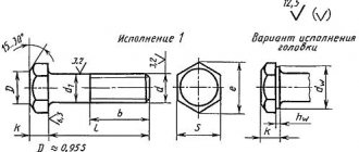
Dies are used to produce external threads on cylindrical metal workpieces. You can cut threads in the inside of the holes using taps.
Knife blades are multi-bladed tools. In shape, they are metal strips on which numerous teeth of the same height are made. They are used if you need to cut off a piece of a workpiece or make grooves in it. Translational movements in this case are the main workers.
Chisels are used to sharpen teeth on various parts. For example, on gears, shafts, etc. Gears can also be machined with shavers. The action of these tools resembles scraping. As a result, the parts are finished.
The group of abrasive tools includes various devices and materials for finishing parts. These can be special powders, grains, bars, crystals, etc.
Basic metal cutting tools
Tools for metal processing are classified by design and type of surface being processed. In addition, it is necessary to remember that each class is divided into varieties.
By design, blade tools are divided into:
- Cutters used for turning rotating bodies (turning), planing, used for processing flat workpieces, for example, for removing a layer of metal during major repairs of machine tools. During the formation of the workpiece, the cutter moves along the axis of its rotation. The main characteristics of turning tools are the size of the holder. That is, the component on which the cutting plate is fixed has a functional purpose. The grade of material from which the cutting part is made also plays an important role. More on this below.
Turning cutters are divided into through, cutting, threading, and groove. In addition, left and right produce. Some are used with normal feed of a caliper with a cutter attached to it, others with reverse feed.
- Drills are an axial type tool. They can be manufactured with one or more blade edges. They are used to form holes in the workpiece. They are formed when the drill rotates around its axis and feeds it into the body of the workpiece. Drills are divided into right and left; the latter are used in mechanized drilling of parts. For example, when preparing holes in car engine housings. This class also includes reamers, countersinks, counterbores, etc. They are designed for processing holes after drilling. For example, with the help of reamers, the resulting holes are finished, that is, they are brought to the required size and surface roughness.
- Files are a tool in the form of rods or plates, on the surface of which a large number of cutting teeth are formed. Designed for manual work with metal. With their help, burrs and irregularities are removed from the product.
- Broaches are rods with blades applied to the surface. They are used to produce shaped holes, for example, keyway or splined grooves in pulleys or gears. The broach is a rod, the diameter of which gradually increases towards its tail.
- Mills are an axial blade tool designed for turning workpieces that are fixed on the work table and move with it relative to a rotating cutter. They are divided into cutters for general use, worm cutters, for producing gears, engraving cutters, key cutters, etc. They are used to produce complex surfaces, for example, in the production of molds or dies intended for metal forming.
- To obtain external and internal threads, two main types of cutting tools are used - taps and dies (dies). The tap is a steel rod on the surface of which there are longitudinal flats and grooves that form cutting edges. The die is a disk with cutting blades formed inside it. External threads are produced using dies. They produce two types of taps - hand and machine. The first ones are used for manual processing. The second ones are installed in machine tools. It should be noted that machine taps can also be used for manual processing of holes.
- For the production of gears, cutters, gear cutters, and shaver are used.
- Abrasive and grinding wheels are used for rough and finishing metal processing. This tool is a circle made of an abrasive material, such as silicon carbide. Small particles of abrasive remove a specified layer of metal. Such circles are used for cleaning surfaces from traces of corrosion and processing products after heat treatment.
The above is a general classification of cutting tools. Meanwhile, all tools produced in the country must comply with GOST requirements; there are standards for turning tools, taps and dies.
One of the main regulatory documents that defines some parameters of a cutting tool is GOST 25751-83. It defines terms used in industry and technology, which are common to all types of blade cutting tools, in addition, it defines terms and concepts related to metal-cutting tools.
All presented tools meet the accuracy standards defined in GOST and TU. In addition to them, some industries use tools manufactured on the basis of industry standards.
Types of treated surfaces
In addition to design features, metal cutting equipment can be classified according to other criteria. For example, depending on the type of surface for which the equipment is intended to be processed. Based on this criterion, the following varieties can be distinguished:
- Products used to work with bodies of rotation of flat and external shaped surfaces. This group of equipment includes cutters, abrasive wheels, cutters and similar tools.
- Equipment that allows you to process holes. This group includes drills, broaches, boring cutters, and countersinks.
- Devices for cutting threads. Similar products include knurling rollers, taps, and dies.
- Products that allow processing of parts whose main element is teeth, that is, splined shafts, sprockets, etc. For this purpose, shaver, grinding wheels, cutters, rolling cutters, and disk cutters are used.
Tapping threads
Milling machines drill holes using taps or by thread milling. Each method has advantages and disadvantages, but keep in mind that tapping is usually faster and cheaper.
Types of taps
Roller tap (left) and regular cutting tap (right)
The two main categories of taps are roller (knurl) and cutting (regular) taps. Rolling taps
do not produce chips, which is a big advantage.
Basically, they produce threads by cold forming the material, which means they create stronger threads. In addition, rolling taps are stronger than cutting taps
, so they are less prone to breakage and have a longer lifespan. In general, rolling taps are preferred over cutting taps, but they are not suitable for every material. If a material consistently produces chips when drilled, it is a good candidate for using a knurl tap. Another important criterion is hardness. Although many may think that these taps are only suitable for aluminum, in fact, a knurl tap can sometimes be used for materials with a hardness of over 36 HRC, or about 340 HRC. according to Brinell. In fact, this includes a surprisingly wide range of materials, including many steels.
There are also medium and finishing taps. The latter have flat bases for marking blind holes. Be careful, blind holes are notorious causes of tap failure. Roll taps have a great advantage when cutting blind holes because they do not produce chips. If you can provide a little extra depth in a blind hole where the threads won't reach, you can also use a cutting tap.
You can also get other forms of cutting taps, such as a spiral flute tap, which will make removing chips from holes much easier.
Rigid tapping, tapping heads and floating tap chucks
Selecting the tap you want to use isn't everything. You must adapt the tool holder correctly to your machine. Taps must be inserted in such a way that the feed rate is synchronized with the number of spindle revolutions, depending on the thread being cut. Too large or small a value puts pressure on the tap and creates problems. The value depends on whether your machine can accurately synchronize the feed rate with the spindle speed. If so, the tap may simply be clamped in the spindle. Otherwise, you need a holder with play so that the tap is fed into the hole due to its rotation as the thread is cut. Free play along the rotating axis will relieve spindle pressure while maintaining feedrate.
Blind holes are not easy to achieve without hard tapping because the spindle may still spin for some time after the stop command and it will be difficult to get it to spin just the right number of times. The backlash tool holder described above can help if you stay within the backlash limits.
Two types of holders used when rigid tapping is not available are the die head and the floating chuck.
Standard Die Head:
The die head has a clamp, friction clutch, axial free play and a reverse device that automatically changes the direction of rotation when the feed direction changes. Threading heads were originally created to make threading easier on drill presses and hand-held milling machines. They can be used on CNC machines, although they are not as common as rigid tapping and floating chucks.
Standard floating cartridge:
These holders are spring-loaded along an axis and allow the tap to find its own position as the thread is cut.
Tips for cutting threads
— Our tip #1 – Avoid tap breakage at all costs
: Drill the correct size holes to avoid excessive torque on the tap.
— Important for beginners: Avoid taps from hardware stores!
Tools made for machine tools are not as expensive and work much better.
— Use a knurl tap
, if this is possible, such a tap is more durable (i.e. less susceptible to breakage), and the thread will also be stronger. Additionally, these taps do not produce chips, so chips will not get stuck in a blind hole. Their only drawback is the limited rigidity of the material on which they can be used.
— Consider using a good lubricant
. You can place a cup of oil on the machine table and g-code it to drop the tap into the cup before starting work.
— Consider difficult holes with re-tapping threads
. For the most part, you will want the tap to retract when cutting hard to synchronize it to the same thread as it moves in and out of the holes. Ratchet tapping is used with cutting taps only. Retapping is also an excellent way to remove long, stringy chips that form when cutting plastics and some other materials.
- For the hardest materials, and especially when the cost per broken tap is very high, consider thread milling
. The likelihood of breaking a thread cutter is much lower. And even if it does, it won't get stuck in the hole, which would happen with a tap.