Any line for supplying a private house with water consists of devices that automate the process of its operation. One of its main components is a storage tank, when installing it yourself, it is important to know what the connection diagram of the hydraulic accumulator to the pump and water supply system looks like.
In addition to the correct connection, the hydraulic tank must be precisely adjusted, creating optimal pressure inside when working in an individual water intake system. To perform this work, you need plumbing tools and adherence to technology during adjustment work.
Why do you need a hydraulic tank?
The hydraulic accumulator is always placed in the individual water supply main; it works constantly and performs the following functions:
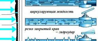
- Smoothes out the negative consequences of hydraulic shocks. When the electric pump is triggered, the water flow suddenly stops or accelerates, while the liquid acts on the pipeline and its components with physical force. Connecting the hydraulic accumulator to the water supply system allows you to smoothly accumulate and release water due to the plastic rubber membrane located inside.
- Connecting a hydraulic tank reduces the number of cycles of turning on and off a borehole or sump electric pump due to the accumulation of liquid, which is released into the line during use and maintains pressure in it, preventing the electric pump from turning on.
- Hydraulic accumulators create an emergency supply of water in times of power outages or pumping equipment failure.
- The connection diagram of the hydraulic accumulator to the pump and water supply system normalizes the pressure, allowing it to avoid sudden changes in the event of unstable operation of the electric pump.
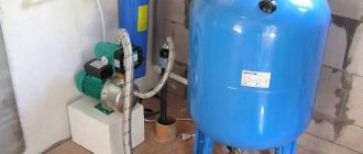
Rice. 1 Hydraulic accumulators for water mains
Injecting water into the hydraulic accumulator
When the correct air pressure has already been set, you can connect the accumulator to the system. After connecting it, you need to carefully observe the pressure gauge. All hydraulic accumulators indicate normal and maximum pressure values, exceeding which is unacceptable. Manual disconnection of the pump from the network occurs when the normal pressure of the accumulator is reached, when the limit value of the pump pressure is reached. This occurs when the increase in pressure stops.
The pump power is usually not enough to pump the tank to the limit, but this is not even particularly necessary, because when pumping, the service life of both the pump and the bulb is reduced. Most often, the pressure limit for switching off is set 1-2 atm higher than switching on.
For example, when the pressure gauge reads 3 atm, which is sufficient for the needs of the owner of the pumping station, you need to turn off the pump and slowly rotate the nut of the small spring (delta P) to decrease until the mechanism is activated. After this, you need to open the tap and drain the water from the system. While observing the pressure gauge, you need to note the value at which the relay turns on - this is the lower pressure limit when the pump turns on. This indicator should be slightly higher than the pressure in an empty accumulator (by 0.1-0.3 atm). This will make it possible to serve the pear for a longer period of time.
When the nut of the large spring P rotates, the lower limit is set. To do this, you need to turn on the pump and wait until the pressure reaches the desired level. After this, it is necessary to adjust the nut of the small spring “delta P” and complete the adjustment of the accumulator.
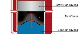
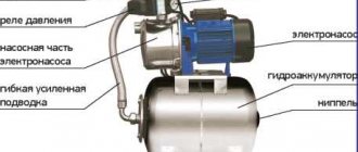
Hydraulic tank design
The design of the hydraulic accumulator is not complicated; it consists of a metal tank with a built-in pear-shaped membrane or a flat rubber diaphragm. The diaphragm is attached across the body between its halves, a pear-shaped cylinder is installed at the inlet near the neck - this type is used to supply water for individual water supply. A nipple is installed in the rear part of the metal container, with the help of which air is pumped into the hydraulic tank body, adjusting its internal pressure to the system.
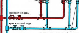
Hydraulic tanks are produced for heating systems, hot water (red) and cold water supply (blue). Depending on the volume of the hydraulic tank and the installation method, there are models with a horizontal arrangement and volumetric vertical units that are installed on legs.
Horizontal models of small capacity are more often used in pumping stations with a built-in surface-type centrifugal electric pump and elements of an automatic control system. Vertical hydraulic tanks are used separately; they are more convenient to install when working with submersible electric pumps. Vertical tanks are structurally different from horizontal models: the membrane shell is attached to the upper and lower parts of the body, in addition to the nipple for pumping air, they have an additional fitting for bleeding it out of the rubber shell.
When purchasing a hydraulic tank, you should know that its useful volume when liquid accumulates is no more than 30% of the total.
Rice. 2 Hydraulic tank design
How a hydraulic accumulator works - simple and reliable design
A stable functioning water supply system of a private home is the merit of its owner. People who have experienced the installation and operation of autonomous water supply networks can imagine how difficult it is to avoid interruptions in the water supply in such complexes. Sometimes just one pressure surge is enough for expensive equipment connected to the water supply (for example, a water heater, a dishwasher) to fail. There is only one solution to such a problem - installing a hydraulic accumulator. It maintains a given pressure in the system, creates a certain supply of water and eliminates the risk of breakdown of household electrical equipment.
The need to install such a device is obvious.
The design of the hydraulic accumulator is quite simple. It is made in the form of a metal tank, inside of which a rubber membrane is installed. The latter is visually similar to a pear. The membrane is fixed to the hydraulic tank body by means of a special flange with a pipe. Water accumulates in the bulb under pressure. The space between the battery housing and the membrane is filled with compressed air (if we are talking about household devices) or an inert gas composition (industrial hydraulic tanks). The pressure in the system is maintained at 1.5–3 bar. Air can be pumped into a hydraulic accumulator at home using a regular car or even bicycle pump.
The devices under consideration are usually divided into three types:
- 1. For cold water supply systems. The device supplies water and stores it, protects pumping equipment from early wear and tear caused by frequent system switching on and off, and protects electrical equipment in the house from water hammer.
- 2. For hot water. Such a hydraulic accumulator for water supply systems can operate in high-temperature environments without problems.
- 3. Expansion tanks. They are designed for closed water heating systems.
The design and operating principle of all these devices are identical. We will talk about how such equipment functions further.
Operating principle of the hydraulic tank
Typically, the inner bulb is located in a container of air at a standard pressure of 1.5 bar. When turned on, water is supplied by an electric pump installed in the well into the tank, filling the rubber bulb - it increases in volume, compressing the air space inside. When the pressure (standard 3 bar) reaches the threshold of the automatic relay, the electric pump turns off and the flow of water into the line stops.
When turned on, water flows to the consumer under pressure created by a rubber membrane compressed by air. Upon reaching the minimum level of 1.7 bar. the relay closes the power supply circuit of the electric pump and the line is filled.
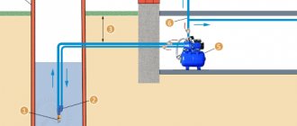
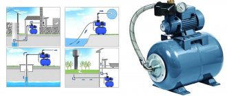
Fig. 3 Example of installing a hydraulic accumulator in a water supply system with a submersible pump
Functions, purpose, types
Installation location - in a pit or in a house
In the water supply system of a private house without a hydraulic accumulator, the pump turns on whenever water flows somewhere. These frequent starts lead to wear and tear on the equipment. And not only the pump, but the entire system as a whole. After all, every time there is an abrupt increase in pressure, and this is a water hammer. To reduce the number of pump starts and smooth out water hammer, a hydraulic accumulator is used. The same device is called an expansion or membrane tank, a hydraulic tank.
Purpose
We found out one of the functions of hydraulic accumulators - to smooth out water hammer. But there are others:
- Reducing the number of pump starts. There is some water in the tank. With a small flow rate - wash your hands, wash yourself - water flows from the tank, the pump does not turn on. It will turn on only when there is very little left.
- Maintaining stable pressure. This function requires one more element - a water pressure switch, but they maintain the pressure within the required limits.
- Create a small supply of water in case of power outage.
Installing a hydraulic accumulator in a pit
It is not surprising that most private water supply systems have this device - there are many advantages from its use.
Kinds
The hydraulic accumulator is a tank made of sheet metal divided into two parts by an elastic membrane. There are two types of membrane - diaphragm and balloon (bulb). The diaphragm is attached across the tank, a pear-shaped cylinder is secured at the inlet around the inlet pipe.
According to their purpose, they are of three types:
- for cold water;
- for hot water;
- for heating systems.
Hydraulic tanks for heating are painted red, tanks for water supply are painted blue. Expansion tanks for heating are usually smaller in size and lower in price. This is due to the membrane material - for water supply it must be neutral, because the water in the pipeline is potable.
Two types of hydraulic accumulators
Depending on the type of arrangement, hydraulic accumulators can be horizontal or vertical. Vertical ones are equipped with legs; some models have plates for hanging on the wall. It is the elongated upward models that are most often used when independently creating water supply systems for a private home - they take up less space. The connection of a hydraulic accumulator of this type is standard - through a 1-inch outlet.
Horizontal models are usually equipped with pumping stations with surface-type pumps. Then the pump is placed on top of the tank. It turns out compact.
Principle of operation
Radial membranes (in the form of a plate) are used mainly in gyroaccumulators for heating systems. For water supply, a rubber bulb is usually installed inside. How does such a system work? As long as there is only air inside, the pressure inside is standard - the one that was set at the factory (1.5 atm) or that you set yourself. The pump turns on, begins to pump water into the tank, and the pear begins to increase in size. Water gradually fills an increasingly larger volume, increasingly compressing the air that is located between the wall of the tank and the membrane. When a certain pressure is reached (usually for one-story houses it is 2.8 - 3 atm), the pump is turned off, and the pressure in the system stabilizes. When you open a tap or other water flow, it comes from the accumulator. It flows until the pressure in the tank drops below a certain level (usually about 1.6-1.8 atm). After which the pump turns on, the cycle repeats again.
The operating principle of a gyroaccumulator with a pear-shaped membrane
If the flow rate is large and constant - you are filling a bathtub, for example - the pump pumps water in transit, without pumping it into the tank. The tank begins to fill after all the taps are closed.
A water pressure switch is responsible for turning the pump on and off at a certain pressure. In most hydraulic accumulator piping schemes, this device is present - such a system operates in optimal mode. We’ll look at connecting the hydraulic accumulator a little lower, but for now let’s talk about the tank itself and its parameters.
Large tanks
The internal structure of hydraulic accumulators with a volume of 100 liters and above is slightly different. The pear is different - it is attached to the body both at the top and bottom. With this structure, it becomes possible to fight the air that is present in the water. To do this, there is an outlet in the upper part into which you can connect a valve for automatic air release.
The structure of a large hydraulic accumulator
Setting up the hydraulic accumulator when connecting
Before using a water supply system with a hydraulic accumulator in a private house, you need to know what the pressure in the hydraulic accumulator should be for its optimal operation; take a portable pressure gauge to take readings. A typical water line with a standard pressure switch has response thresholds from 1.4 to 2.8 bar, the factory setting of the pressure in the hydraulic tank is 1.5 bar. To ensure that the hydraulic accumulator operates efficiently and is completely filled, the lower threshold for switching on the electric pump is selected at 0.2 bar for a given factory setting. more - a threshold of 1.7 bar is set on the relay.
If during operation or due to a long storage period it is determined that the pressure in the hydraulic tank is insufficient when measured with a pressure gauge, proceed as follows:
- Disconnect the electric pump from the power supply.
- Remove the protective cover and press the hydraulic tank valve in the form of a nipple head at the outlet of the device - if liquid comes from there, then the rubber membrane has been damaged and needs to be replaced. If air comes from the hydraulic tank, its pressure is measured using a car pressure gauge.
- Drain the water from the main by opening the tap closest to the expansion tank.
- Using a hand pump or compressor, pump air into the battery tank until the pressure gauge reads 1.5 bar. If, after automation, the water rises to a certain height (high-rise buildings), the total pressure and operating range of the system are increased based on the fact that 1 bar. equated to 10 meters of vertical water column.
When calculating the required pressure in the hydraulic tank for any range, select its value 10% less than the lower threshold of the relay operation. Selecting this value ensures that the built-in membrane will expand and contract within a small range and accordingly increase the service life of it and the entire expansion tank.
Fig.5 Setting up the hydraulic accumulator
Optimal air pressure
For household appliances to work normally, the pressure in the hydraulic tank must be in the range of 1.4-2.8 atm. For better preservation of the membrane, it is necessary that the pressure in the water supply system be 0.1-0.2 atm. exceeded the pressure in the tank. For example, if the pressure inside the membrane tank is 1.5 atm, then in the system it should be 1.6 atm.
It is this value that should be set on the water pressure switch, which works in conjunction with the hydraulic accumulator. For a one-story country house, this setting is considered optimal. If we are talking about a two-story cottage, the pressure will have to be increased. To calculate its optimal value, use the following formula:
Vatm.=(Hmax+6)/10
In this formula V atm. is the optimal pressure, and Hmax is the height of the highest water intake point. As a rule, we are talking about the soul. To get the required value, you should calculate the height of the shower head relative to the accumulator. The obtained data is entered into the formula. As a result of the calculation, the optimal pressure value that should be in the tank will be obtained.
Please note that the obtained value should not exceed the maximum permissible characteristics for other household and plumbing appliances, otherwise they will simply fail.
If we talk about an independent water supply system at home in a simplified way, then its components are:
- pump,
- hydraulic accumulator,
- pressure switch,
- check valve,
- pressure gauge
The last element is used to quickly control the pressure. Its constant presence in the water supply system is not necessary. It can only be connected at the moment when test measurements are being made.
When a surface pump is involved in the circuit, the hydraulic tank is mounted next to it. The check valve is installed on the suction pipeline, and the remaining elements form a single bundle, connecting to each other using a five-pin fitting.
The five-pin device is ideal for this purpose, since it has leads of different diameters. The incoming and outgoing pipelines and some other elements of the connection can be connected to the fitting using American connectors to facilitate preventive and repair work on individual sections of the water supply system.
However, this fitting can be replaced with a bunch of connecting elements. But why?
In this diagram, the connection order is clearly visible.
When connecting the fitting to the hydraulic accumulator, you need to make sure that the connection is tight. So, the hydraulic accumulator is connected to the pump as follows:
- one inch lead connects the fitting itself to the hydraulic tank pipe;
- a pressure gauge and pressure switch are connected to the quarter-inch terminals;
- There are two free inch terminals left, to which the pipe from the pump is mounted, as well as the wiring going to the water consumers.
If a surface pump operates in the circuit, then it is better to connect the hydraulic accumulator to it using a flexible hose with a metal winding.
The hydraulic accumulator is connected to the submersible pump in exactly the same way. A feature of this circuit is the location of the check valve, which has nothing to do with the issues we are considering today.
Determination of tank parameters
In most cases of inclusions, hydraulic tanks for water supply are installed according to the principle: the larger the volume, the better. But too large a volume is not always justified: the hydraulic tank will take up a lot of useful space, the water will stagnate in it, and if power outages happen very rarely, there is simply no need for it. A hydraulic tank that is too small is also ineffective - if a powerful pump is used, it will turn on and off frequently and quickly fail. If a situation arises when installation space is limited or financial resources do not allow you to purchase a large-capacity storage tank, you can calculate its minimum volume using the formula below.
Rice. 6 How to correctly calculate the volume of a hydraulic tank in a water supply system
Another calculation method is to calculate the required volume of the hydraulic tank based on the power of the electric pump used.
Recently, modern high-tech electric pumps with soft start and stop, frequency control of the speed of rotation of the impellers depending on water consumption have appeared on the market. In this case, there is no need for a large-volume hydraulic tank - soft start-up and adjustment do not cause water hammer, as in systems with conventional electric pumps. Automatic control units of high-tech devices with frequency control have a built-in hydraulic tank of a very small volume, designed for its pump group.
Fig. 7 Table of calculated values of pressure and volume of the hydraulic tank depending on the operating modes of the water supply line
Role in the water supply network
It would seem that the device simply passes water through itself. Could you do without it? In fact, it is with the help of a hydraulic tank that stable pressure is maintained in the water supply system. The water pump, if present, does not turn on so often, which allows you to use its operational resource economically. In addition, the water extraction and transportation system is reliably protected from water hammer.
If for any reason the voltage in the electrical network is lost, a small “emergency” supply of water in the tank will help solve priority economic problems. Let us clarify the list of advantages that this fairly simple device provides.
- Premature pump wear. There is a certain supply of water in the membrane tank. It satisfies the primary needs of cottage owners. And only when the supply runs out will the pump turn on. It should be noted that all pumps have a turn-on rate of an hour. If there is a hydraulic accumulator, this figure will not be exceeded, and the unit will last longer.
- Stabilization of pressure in the system. If you turn on two taps at the same time, for example in the bathroom and in the kitchen, pressure changes can affect the water temperature. This is very unpleasant, especially for those household members who are taking a shower at this moment. Thanks to the hydraulic accumulator, such misunderstandings can be avoided.
- Water hammer. These phenomena, which can damage the pipeline, can occur when the pump is turned on. With a hydraulic tank, the risk of water hammer is virtually eliminated.
- Water supply. In a country house, the problem of water supply is especially acute. If there is a sudden power outage and the pump cannot perform its functions, then it is no longer necessary to store a supply of water in a bucket or other container to solve urgent problems. It is available in the hydraulic accumulator tank and is regularly updated.
Obviously, the presence of this device in a water supply system independent of centralized networks is not accidental. It is necessary and useful.
The hydraulic accumulator in the water supply circuit performs a number of significant functions: it protects equipment from water hammer, provides a supply of water, and creates conditions for automating its intake.
How to choose a hydraulic accumulator
When choosing a hydraulic accumulator, it is better to give preference to models with a rubber bulb - in membrane types, the liquid comes into contact with the metal body, which can cause corrosion.
The main working element of a balloon hydraulic tank is a pear-shaped membrane, the quality of which determines its service life, while the body material plays a less important role, since it does not come into contact with water. The usual material for making a pear is isobutated food rubber; when choosing a model for external installation, special attention should be paid to the flange to which the rubber membrane is attached. Preference should be given to models whose flange is made of thick stainless steel or galvanized steel - such a product will last 10-15 years without losing its tightness.
Another advantage of a balloon tank is the ease of replacing the rubber membrane. To do this, unscrew several hex bolts securing the flange and remove it along with the shell.
Rice. 9 Vertical hydraulic tanks in the water line
The principle of operation of the hydraulic tank and how it all happens
When the pumping equipment is turned on, water begins to flow into the membrane. The volume of the pear increases. This leads to the fact that the air in the accumulator housing (outside the membrane) is compressed and forms some pressure. When the specified value is reached, the electric pump is switched off at the command of the control relay. Compressed air presses on the water in the bulb and pushes it through the water supply. The consumer opens the tap. Water begins to flow through it, coming from a hydraulic tank under a given pressure.
After some time, there is less water in the membrane. Because of this, the pressure level also decreases. When it becomes minimal, the relay is activated again and the pump automatically starts. Then everything goes according to the scheme already described above. The pumping equipment starts more often, the smaller the hydraulic tank is used. The optimal capacity of a hydraulic accumulator for domestic use is 100 liters. In this case, the relay operates no more than 5–15 times in 60 minutes. With such indicators, wear of hydraulic equipment will be minimal
It is important to understand that more frequent pump starts lead to premature wear of the membrane and other battery elements
Water entering household hydraulic tanks most often rises from wells or specially equipped wells. This liquid is characterized by increased oxygen saturation. It can accumulate in the pear, released during the functioning of the home plumbing. Oxygen must be periodically removed from the system. For these purposes, in many models of hydraulic accumulators, a special valve is mounted on the body (in its upper part). If necessary, it independently releases excess oxygen.
Active use of the hydraulic tank often causes a decrease in air pressure. No equipment is insured against such natural wear and tear. Experts recommend completely emptying the battery and checking the pressure reading every 10–12 months. This simple procedure will guarantee comfortable use of water supply in a private home.
Installing a hydraulic accumulator
After purchasing a suitable model of electric pump for a well or well and connecting it to the pipeline, calculating the volume and purchasing the required hydraulic tank, you need to install it correctly. If the model has a large volume and is installed on vertical legs, you should use the following recommendations:
- It is better to install a volumetric storage tank at the highest point of the house (attic, second floor) - this will create maximum pressure in the water line.
- The floor in the room must be level, humidity must not exceed established standards in order to avoid corrosion of the galvanized flange and surface of the tank.
- It is better to connect the device using a flexible pressure hose in a stainless steel braid and one-inch diameter union nuts made of brass. Avoid supply hoses with aluminum braiding and mounting couplings made from cheap silumin, a brittle alloy of aluminum and silicon.
Rice. 10 Connection diagram of the hydraulic accumulator to the pump and water supply system
Expansion tank piping
Before connecting a hydraulic accumulator for individual water supply systems, prepare components: automatic devices, filters and adapter couplings for connecting HDPE pipes. After connecting the electric pump to the HDPE water supply using plastic adapter couplings and placing it in the well, further assembly work is carried out in the following sequence:
- At the outlet of the water pipe from the pump, a ball valve and a coarse filter are installed to remove sand from the water.
- After the filter, a tee with a hole diameter suitable for connecting automation is installed. An adapter coupling is screwed into its upper outlet to connect the relay.
- To connect the pressure switch and pressure gauge to the electric pump, a standard five-inlet fitting is used, which is connected to the tee using an adapter.
- At the outlet of a fitting with an external thread with a diameter of 1 inch, a ball valve with a union nut is installed - this will allow repairs and replacement of components without draining the water from the entire water main.
- A hydraulic accumulator is connected to the outlet of the fitting with a 1-inch internal thread using a flexible liner.
- Next, a pressure gauge and a pressure switch are installed in the five-pin fitting, and a dry-running relay is screwed into the tee.
- At the end, connect the electrical power cable to the relay - installation of the automation can be considered complete.
Many people prefer to install all automation using connecting fittings directly at the outlet of the accumulator - this technique does not require an underwater hose.
Rice. 11 How to install a hydraulic accumulator in a line
The hydraulic tank is the main component in automatic control systems for electric pumps, necessary to reduce the load on the water main and reduce the operation cycles of pumping equipment. Its connection to the pipeline and adjustment are quite easy to do with your own hands using the simplest plumbing tools. To correctly select an expansion tank, you can use a not too complicated formula or determine its parameters approximately depending on the flow volume or power of the pumping equipment.
Is there a difference between vertical and horizontal hydraulic accumulators?
The tanks described in the article are mounted in two ways: vertically and horizontally. The specific type of hydraulic accumulator should be selected based on how compactly it will fit into the area that will be allocated for its installation. In addition, in vertical and horizontal devices, air is removed from the membrane differently
It is important. In vertical devices, the release of accumulated oxygen is carried out using a safety valve (we have already mentioned it)
But in horizontal ones it is necessary to additionally install a special pipeline to remove air. Structurally, the additional line consists of a ball valve, a drain and a nipple (it is called an outlet valve).
Please pay attention to the following nuances:
- Vertical accumulators with a volume of less than 100 l are never equipped with a safety valve. Bleeding air in such devices is carried out by completely emptying them.
- It makes more sense to connect horizontal hydraulic tanks to external pumps, and vertical ones to submersible ones installed inside a room specially designated for them.
The ability to bleed air must be present in any hydraulic tank. If you do not free the equipment from the oxygen accumulated in it, air pockets will very quickly appear in the water supply. They will not allow you to effectively operate your home water supply system.