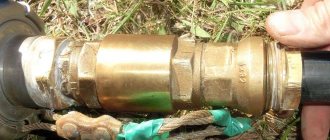
Where is it installed in the heating system?
The general purpose of a check valve is to allow coolant flow in one direction and prevent it from moving back. They do not require power or any other conditions to operate; they operate from the movement of liquids. A check valve for heating is installed in all positions where backflow and parasitic circuits may occur.
In a heating system with several branches, a check valve is placed on the return pipeline. This prevents the pump from “pushing” the flow in the opposite direction.
The same devices are installed in cold and hot water supply. Those intended for heating are distinguished by the fact that materials are used that can withstand prolonged exposure to elevated temperatures. If there are rubber gaskets, then heat-resistant rubber is used. The same applies to plastic parts.
If we talk specifically about heating systems (HC), then a check valve is installed:
- To a bypass with a circulation pump in the piping of a solid fuel boiler - to ensure operation of the system in gravity mode (with natural circulation). In this case, models with the least resistance are installed, which operate easily and quickly - immediately when a flow from natural circulation appears. The function of the valve, in this case, is not to bypass the coolant when the pump is running.
- On the return pipeline when installing an indirect heating boiler. Why install a check valve in this case? To prevent the flow of coolant in the opposite direction when the circulation pump is operating.
- With a branched heating system (for example, on several floors), on each branch. These check valves prevent the coolant from being “pulled” if one of the branches is turned off (when using one circulation pump).
- On the system's cold water make-up line. Here, in addition to the shut-off valve, a return valve is also needed. Since sometimes the pressure in the water supply is lower than in the heating system. Then, when opening the tap to refuel the system, without a check valve, the coolant will “go” into the water supply system.
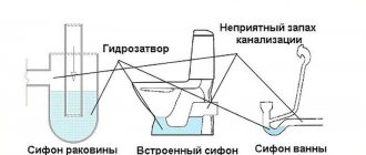
Symbol of a check valve in the diagram
In the diagrams, the check valve is designated as two triangles with their vertices directed towards each other. One of the triangles is shaded. The installation location in the branch is almost any. The main thing is that it exists. The direction of flow is indicated by an arrow on the housing. The coolant flows in this direction. In the opposite case, it overlaps. When installing, carefully follow the arrow (you can also focus on the locking element).
Types of check valves, their design and operating principle
The check valve device is simple. There is a slightly tapered seat and a locking element. With the “correct” flow, the shut-off element is pushed away from the bottleneck. As soon as the direction changes, he presses against the saddle, blocking the passage. By the way, there should be an arrow on the body that indicates the “correct” direction of water movement.
How a water check valve works and how it works
Basically, check valves are distinguished by the type of shut-off element. He can be:
- ball type (ball);
- disc-shaped;
- disk;
- petal or bivalve.
In a ball valve, the ball is “free floating”. It is not attached to anything and is transported by water. Quite a reliable system. It’s just that it doesn’t always cover the saddle tightly enough, so it’s used quite rarely.
Types of check valves for water
Disc-shaped ones can be lifting or rotating. Rotary, as well as ball, open and close under the influence of water flow. Lifting ones have a spring-loaded rod. In the “normal position” the passage is closed; when water pressure appears, it presses the spring, pushing the locking element upward.
The most common type in home water supply systems is the disc check valve. It differs in that fittings of this type can be small in size. And the design is simple and reliable. The locking disc is placed across the flow and is pressed against the seat by a spring. Water squeezes the spring, clearing its way.
A check valve is a device to prevent the reverse movement of the transported medium
There is also a two-leaf valve for water. Its locking element consists of two halves of the disk (petals), which are fixed to the axis. Hence another name for this model - petal. They are held closed by springs. The water entering the water supply system presses them back, folding them and pressing them against each other. This type has the least hydraulic resistance. In some cases (with a long suction line) this may be important.
Operating principle of a check valve
First of all, it should be noted that check valves are not installed “just in case,” but only if necessary, if there is no other technical solution. This is due to the fact that the elements often have considerable hydraulic resistance, depending on the design. This introduces some restrictions when using check valves for heating with natural circulation. The reason is too low coolant pressure in the system.
An exception is gravity valves with a rotary damper; some of their models are capable of opening the path of coolant at a minimum pressure of 0.001 Bar.
Despite the differences in design, most products are equipped with one key part - a spring. It is an actuator that closes the valve when normal conditions change; this is the principle of operation of the check valve. The force expended to overcome the elasticity of the spring determines the magnitude of the hydraulic resistance of the mechanism. For circuits with different operating parameters, products are selected that have the appropriate elasticity and massiveness of the spring.
What does the spring act on? Its task is to keep the locking device closed; this is its normal state. Then the fluid flow flowing from one side can overcome the elastic force of the spring, open the obstacle and move further along the pipe. An attempt to change the direction of the flow and flow in the other direction will lead to nothing - the shut-off device will slam shut, relying on the tide in the body. In this place there is a sealing element that makes the check valve in the heating system completely sealed.
Shut-off valves intended for use in heating circuits are made from the following materials:
- gray cast iron;
- steel;
- brass;
- stainless steel.
Materials, markings, sizes
The check valve for water is made of stainless steel, brass, larger sizes are made of cast iron. For household networks, brass is usually used - it is not too expensive and durable. Stainless steel is, of course, better, but it is usually not the body that fails, but the locking element. This is where you should approach your choice carefully.
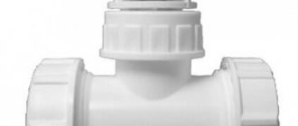
For plastic plumbing systems, check valves are made from the same material. They come in polypropylene and plastic (for HDPE and LDPE). The latter can be welded/glued or threaded. You can, of course, solder adapters to brass, install a brass valve, then again an adapter from brass to PPR or plastic. But such a unit is more expensive. And the more connection points, the lower the reliability of the system.
For plastic and polypropylene systems there are check valves made of the same material
The material of the locking element is brass, stainless steel or plastic. Here, by the way, it’s hard to say which is better. Steel and brass are more durable, but if a grain of sand gets between the edge of the disk and the body, the valve jams and it is not always possible to return it to functionality. Plastic wears out faster, but it doesn’t jam. In this regard, it is more reliable. It’s not for nothing that some manufacturers of pumping stations install check valves with plastic discs. And as a rule, everything works for 5-8 years without failures. Then the check valve begins to “poison” and is replaced.
What is indicated in the labeling
A few words about the marking of the check valve. It states:
- Type
- Conditional pass
- Conditional pressure
- GOST according to which it is manufactured. For Russia, this is GOST 27477-87, but there are not only domestic products on the market.
Return valve for water: marking according to GOST
The conditional diameter is designated as DU or DN. When choosing this parameter, you need to focus on other fittings or pipeline diameter. They must match. For example, you will install a check water valve after a submersible pump, and a filter next to it. All three components must have the same nominal diameter. For example, all should have DN 32 or DN 32 written on them.
A few words about conditional pressure. This is the pressure in the system at which the shut-off valves remain operational. You should definitely take it no less than your working pressure. In the case of apartments - no less testing. According to the standard, it exceeds the working one by 50%, and in real conditions it can be much higher. You can find out the pressure for your home from the management company or plumbers.
What else to pay attention to
Each product must come with a passport or description. It indicates the temperature of the working environment. Not all valves can work with hot water or in a heating system. In addition, it is indicated in what position they can work. Some should only stand horizontally, others only vertically. There are also universal ones, for example, disk ones. That's why they are popular.
Opening pressure characterizes the “sensitivity” of the valve. For private networks it rarely matters. Only on supply lines close to the critical length.
Also pay attention to the connecting thread - it can be internal or external. Choose based on ease of installation. Don't forget about the arrow that indicates the direction of water movement.
Dimensions of check valves for water
The size of a check valve for water is calculated according to the nominal diameter and they are produced for all - even the smallest or largest pipeline diameters. The smallest is DN 10 (10 mm nominal bore), the largest is DN 400. They are the same sizes as all other shut-off valves: taps, valves, drains, etc. Conditional pressure can also be referred to as “dimensions”. The lowest is 0.25 MPa, the highest is 250 MPa.
Each company produces check valves for water in several sizes.
This does not mean that any of the valves will be in any variant. The most popular sizes are up to DN 40. Next come the main ones, and they are usually purchased by enterprises. You won't find them in retail stores.
And also, please note that for different companies, with the same nominal diameter, the external dimensions of the device may differ. The length is understandable. Here the chamber in which the locking plate is located may be larger or smaller. The diameters of the chambers also differ. But the difference in the area of the connecting thread can only be due to the thickness of the walls. For private houses this is not so scary. Here the maximum working pressure is 4-6 Atm. But for high-rise buildings it can be critical.
How to check
The easiest way to test a check valve is to blow into it in the direction that is blocking it. No air should pass through. At all. No way. Also try pressing on the plate. The rod should move smoothly. No clicks, friction, distortions.
How to test a check valve: blow into it and check for smoothness
Also inspect the seat and disc. Especially in the place where they are adjacent to each other. Everything should be even/smooth. The tightness of this type of fitting depends on how accurately everything fits. In more expensive models, a rubber/polymer/plastic sealing ring is installed on the plate. Needless to say, it should lie flat, without waves, and there should be no scratches or burrs.
Why is a check valve needed in heating systems?
When deciding where and how to install the valve, you should first of all take into account that its presence is undesirable in any system. The fact is that the device has a fairly high hydraulic resistance in the range from 0.1 to 1 meter of a horizontal pipeline section, which corresponds to pressure values from 0.1 to 1 atmosphere (bar).
The hydraulic resistance of a pipeline or fittings in the main depends on the flow speed (the volume of pumping); for household systems, the standard range of speeds of movement of the coolant is 0.5 - 1.5 m/s. With these values, the valve resistance is in the range of 0.3 - 0.4 m, which corresponds to a pressure drop in the line of 0.3 - 0.4 bar.
Types of devices and areas of their application
The selection of the device is dictated by the conditions in which it will be used; it depends on the type of heating networks and their internal pressure. An incorrectly selected mechanism can itself cause emergency situations. For example, the liner part that is proposed to be placed inside the cold water meter can completely block its current if the pressure is insufficient, or significantly limit it. On the other hand, installed at the water supply inlet, it will prevent coolant leakage, maintaining pressure, pressure and amount of water in the system.
Gravity check valve for heating
It is also called a firecracker valve and is used only in gravity systems, usually installed at the inlet to the boiler. It consists of a metal “petal”, which is pressed tightly against the edge using a spring.
The spring in the gravity check valve is quite weak and does not interfere with the natural circulation of the coolant.
The spring in such a device is quite weak and does not interfere with the natural circulation of the coolant, like the next presented option.
Ball valve for heating
It is used less often, since there is a danger that the ball, which moves inside the mechanism, opening and closing the flow of water, may jam in one position and then the device will not perform its job properly.
This feature has led to the fact that today the ball check valve is practically not used in heating networks of private houses.
Disc-shaped
This product is used in networks that operate with a pump, as well as those with several active heating circuits. This is due to the fact that the spring located inside the device has greater rigidity, and therefore resistance.
Inside there is a metal or plastic disk (metal is always used for heating), combined with a sleeve on which a spring is attached. Thus, when the proper pressure occurs in the pipe, the plate rises and does not interfere with the flow of coolant. However, as soon as the pressure drops, the opening closes, preventing the outflow of water in the opposite direction.
Coupled
All the products discussed above were completely autonomous and were not subject to external influences, working only in one direction. But in cases where it is necessary, for example, to drain coolant from pipes, a device is needed that makes it possible to open the coolant flow in the opposite direction - such a device is a coupling or valve valve.
When it is necessary to drain coolant from pipes, you need a device that makes it possible to open the coolant flow in the opposite direction; for this, a coupling or valve valve is used.
The choice between a coupling and a valve is most often determined by the internal operating pressure of the network; if it is high, a valve is used; if it is average, a coupling will suffice.
Types of check valve
Despite the fact that all devices of this type perform the same task, they have structural and, therefore, operational differences. Let's take a closer look at each of these types.
Disc type devices
A distinctive feature of the product is the presence of a disc valve. This is a plastic or metal element, the dimensions of which allow it to completely block the flow of coolant if it begins to move in the opposite direction.
The disk is connected to a steel spring. When a liquid moves forward, it is in a compressed state. When changing direction, it straightens and moves the disk from its place, thereby blocking the pipe.
The valve design also includes a sealing gasket, which allows the valve mechanism to sit as tightly as possible in the seat. Therefore, leakage is excluded in serviceable devices.
Design features
One of the most common materials used to make the body of water return valves is brass. The choice of this material is not accidental: this alloy demonstrates exceptionally high resistance to chemically aggressive substances that may be present in water transported through a pipeline in a dissolved or suspended state. Such substances, in particular, include mineral salts, sulfur, oxygen, manganese, iron compounds, etc. The outer surface of the valves, which during their operation is also exposed to negative factors, is often protected with a special coating applied by the galvanic method.
The check valve device requires the presence of a spool, for the manufacture of which brass or durable plastic can also be used. The sealing gasket present in the check valve design can be rubber or silicone. To manufacture an important element of the locking mechanism - the spring - stainless steel is usually used.
Spring check valve device
So, if we talk about the structural elements of a spring check valve, then this device consists of:
- composite type housings, the elements of which are connected to each other by means of threads;
- a locking mechanism, the design of which includes two movable spool plates mounted on a special rod and a sealing gasket;
- a spring installed between the spool plates and the seat at the outlet of the through hole.
The principle of operation of a spring check valve is also quite simple.
- The flow of water entering the check valve under the required pressure acts on the spool and depresses the spring.
- When the spring is compressed, the spool moves along the rod, opening the passage hole and allowing the fluid flow to move freely through the device.
- When the pressure of the water flow in the pipeline on which the check valve is installed drops, or in cases when such a flow begins to move in the wrong direction, the spring returns the spool to its seat, closing the throughput hole of the device.
Rotary check valve device
Thus, the operation scheme of the check valve is quite simple, but nevertheless ensures high reliability of such devices and the efficiency of their use in pipeline systems.
Connection diagram options
Before choosing a check valve, find out its purpose in your heating system. Let’s make the task easier and suggest options for using return valves:
- The valves are placed on separate circuits of a closed circuit, equipped with circulation pumps. The goal is to prevent the occurrence of parasitic flows that impair the operation of heating branches or boilers connected in parallel.
- When installed on a bypass parallel to the pump, the valve helps the system automatically switch to natural circulation mode when the power supply is suddenly cut off.
- Tapping into the make-up pipeline allows you to avoid emptying the heating network in various situations.
Important advice. Do not listen to the “experts” and do not place a spring valve in front of the only circulation pump in a conventional single-circuit system. Assurances that in this way you will protect the pumping unit from water hammer and other nonsense do not correspond to reality.
Piping diagram for 2 boilers - wood-burning and electric - using return valves.
As an example of the correct installation of check valves, we present a diagram for the joint connection of a solid fuel and electric boiler. If one of the pumps stops, the second will inevitably drive the coolant with a parasitic flow in a small circle. You can’t do without shut-off valves here.
Note. A similar situation may arise when connecting a radiator network and an indirect heating boiler with a separate pump without a distribution comb, hydraulic valve or buffer tank.
The second example is typical of gravity systems with natural circulation of water, converted to work with a pump. The main mode is forced, but when the light is turned off, the unit on the bypass will stop and stop pressing the actuating part of the check valve embedded in the direct line. Then the convection flow of water along the main line will resume until electricity is supplied.
Installing a check valve on the make-up is not necessary, but can save you from unexpected problems. A real example from practice: a homeowner decided to increase the pressure in the heating system and opened the feed tap in the boiler room. Since at that time the water utility company was repairing the network and cut off the water supply, the coolant transferred cold water and partially went into the pipe. Instead of refilling, there was emptying, as a result the pressure dropped and the gas boiler stopped.
Types and purpose of check valves
The dimensions of the check valve are small, but without this little detail it will be impossible to maintain the pressure in the water supply system. It belongs to the category of pipeline fittings whose main task is to prevent a reverse change in the flow of water in the pipes of the water supply system.
Household pumping equipment is not designed for its movement in an abnormal direction.
A check valve is used to allow water flow to flow in only one direction, completely blocking its path back (+)
There are models of pumping stations on the market, the manufacturers of which include a check valve. Such options are supplied with a suction hose with a built-in check valve. But in most cases, you have to purchase this fittings yourself.
Such valves are installed both on the suction line and at the entrance to the internal water supply system immediately after the pump with a hydraulic accumulator or in front of the pumping station.
Depending on the installation location in the water supply system diagram, check valves are divided into:
- Bottom. They prevent the reverse movement of water raised from the source when the pumping equipment is turned off. They create conditions for operating the unit without constant filling with water before starting it and the suction line.
- Pipeline. These include axial and valve varieties. Prevents a drop in the operating pressure in the system.
If there is no check valve at the end of the suction pipe of the pumping station, then when the pump stops, water will begin to flow back under the influence of gravity. As a result, air pockets will form in the line, and under “dry running” conditions, the seals will begin to collapse. As a result, water will penetrate into the electric pump and cause it to burn out.
Not only the starting point of the suction line can be equipped with a check valve. To ensure pressure support, it is installed on the pipeline in front of the pumping station or in front of the hydraulic tank when it is located separately
Most modern pumps are protected against such processes. But water for starting will have to be poured into them after each stop of the unit.
In some pump models, it is possible that the impeller spins up completely, which can lead to its failure. Installation of this fittings on the liquid intake line from the source is mandatory, otherwise no electronic protection will help the water pumping unit.
When connecting several pumping stations into a single unit, check valves protect the switched off unit from the pressure of operating devices
With a pipeline check valve the situation is somewhat different. Here it no longer protects the pump, but the water distribution system inside the house. By locking the water in the pipes, preventing it from returning back to the accumulator, the check valve helps maintain the required operating pressure in the system. Without it, water will rush back into the storage tank, causing it to work abnormally.
Check valves increase the efficiency and reliability of the pumping station, while protecting the pump, plumbing and water system from water hammer. Overall, it is an indispensable device. But the water has to expend effort to open the valve, which reduces the pressure of the flow after its passage by 0.1–0.3 atm.
Installing the valve correctly
To avoid making mistakes when choosing and installing a check valve in the right place in the heating system, listen to these simple recommendations:
- To avoid stray flows in adjacent branches, install petal or disc type products. The former are preferable because they do not create increased hydraulic resistance.
- In the bypass assembly of a gravity system, use a ball valve that has virtually zero resistance.
- For refilling, choose an element with a poppet valve designed for high pressure.
Products with gravity butterfly valves are always placed horizontally with the plug facing up - The gravity type reed valve is always mounted horizontally. Moreover, the head of the service nut must be vertical, otherwise the valve will not close and will begin to leak coolant in the opposite direction.
- Do not purchase fittings with a cast iron body. It is heavier and less reliable in operation.
- Check the correct installation by the arrow on the valve body indicating the direction of water flow.
- You cannot install fittings with a spring lock in a circuit with natural circulation - gravity flow will stop due to high resistance.
Disc and leaf valves require periodic maintenance and cleaning. If solids or deposits become trapped under the seat seal, the non-return valve will lose its seal. The best cleaning method is to remove the element and blow off the adjacent surfaces with a compressor.
Possible installation errors
Common mistakes when installing a non-return valve:
- the direction of flow is not taken into account;
- connections are poorly sealed, which can lead to leaks when the valve is closed;
- the cross-section of the device is too large, so it knocks during operation;
- the valve is placed too close to the pump, which causes rattling;
- a lot of plumbing flax was used when winding the threads - the coupling may crack.
Sometimes they forget to remove the through hole plug or the shutter lock.
Advantages and disadvantages
A check valve with a filter helps prevent the plate from jamming in any position.
The check valve has advantages and disadvantages that are common to all types of devices. There will be no hot flow into the riser if cold liquid flows there. This extends the performance of system elements that are designed for a certain temperature. The devices are easy to install and do not create noise during the passage of liquid. Check valves solve the problem only in a specific area; additional control devices are installed for other circuits.
Some mechanisms allow the occurrence of water hammer when the flow passes through the working unit, but this feature of the valve only harms a system with a large diameter. The valves become dirty from the water flow if the system operates with an energy carrier without propylene glycol or other additives. In this case, the disc or plate may become stuck in the open or closed position.
What is the device for?
The shut-off device prevents the fluid flow from flowing in the opposite direction. It is small in size and maintains the required pressure in the system. Let's consider the need to use the device in residential premises. It is used in the following cases:
- On water supply pipes . The circulation of hot and cold water in private and apartment buildings is distributed through separate pipes. Sometimes the pressure difference leads to the fact that hot water squeezes out cold water from the chamber of a household faucet and adjusting the temperature of the liquid becomes impossible. The valve returns the pressure to normal values.
- At the inlet to the water heater . The boiler is filled under pressure. When warming up and pressure increases, the displaced coolant will be directed back into the cold pipe. The fittings prevent outflow.
- In an individual heating system, there are several heating circuits (boiler, heated floor, radiators) having different values of hydraulic and pressure indicators. The locking device normalizes the indicators.
- In front of the meter . The question arises, why do you need to install a check valve on the water meter? The answer is simple: shut-off valves are necessary, because they protect the device from possible damage that can be caused by water hammer, and prevent the turbine from rotating in the opposite direction.
- In an autonomous water supply system, the water supply is provided by a submersible pump. It lifts the liquid to the surface and delivers it into the house at an angle of 5°-10° at a distance of up to 10 m . Installing a check valve will prevent water from flowing into the well when the pump is turned off.
Types of locking elements
Any check valve (the outdated name is non-return) performs a simple task - it does not allow the coolant flow to change direction, passing liquid only in one direction. In water heating schemes, this function is not always needed and is implemented as needed.
The following types of check valves are used in heating systems of private houses and apartments:
- petal;
- disc-shaped;
- ball
Industrial models are installed in large boiler houses and production facilities
Let us analyze the device and operating principle of each type of valve separately. In the future, this will help you understand which product is best to select and install in a specific heating system.
Reed valves
The element, made of brass or stainless steel, consists of the following parts:
- body in the form of a tee with a unscrewing top plug (for maintenance);
- a butterfly valve mounted on an axis by means of a rotary lever;
- a seat with a seal into which the disc fits when closed.
The general design of a reed check valve is shown in the detailed drawing. The principle of operation of the element is as follows: the coolant moving in the indicated direction deflects the locking disc and freely passes further along the pipe. When the direction of water flow is reversed, the valve, under the influence of gravity (or a spring), automatically slams shut and blocks the passage.
Typical gravity seal design
We list the important characteristics of petal check valves installed in heating systems of private houses:
- internal passage diameter – from 15 to 50 mm (½—2 inches);
- maximum working pressure – 16 Bar;
- low hydraulic resistance;
- There is a screw on the side of the body for disassembling and adjusting the shutter axis;
- The gravity version without spring can only work normally in a horizontal position.
The design and operating principle of the rotary valve is shown in detail in the video:
Poppet valves
The principle of operation of a poppet check valve is clear from its design, shown in the drawing:
- Inside the cylindrical brass body there is a platform with a round hole - a saddle.
- On the other side of the part there is a partition with a hole in the center.
- A rod with a disc-type valve at the end equipped with a seal is inserted into the hole in the partition.
- A spring is installed between the partition and the “plate”, pressing the disk to the seat.
Water flowing in the right direction overcomes the elastic force of the spring, opens the valve and moves on. Flow in the opposite direction is impossible - the duct instantly closes. What properties of a check valve are important for heating systems:
- ability to function in any orientation of the body in space;
- working pressure – not less than 10 Bar, diameters DN15 – DN100 (internal);
- type of connection – coupling (internal pipe thread);
- spring lock creates increased hydraulic resistance to fluid flow;
- The seal loses its tightness if solid particles, such as sand, enter.
In the utility networks of private houses and apartments, valves with coupling connections are used.
Disc valves are also used in water supply networks, for example, in conjunction with submersible pumps. The valve prevents water from the pipelines from flowing back into the well or borehole.
Device for pump and pumping station
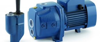
The check valve is not only suitable for water, but also for the pump. The reverse device is in demand in everyday life, as it allows liquids to flow into the house without delay, and is suitable for all types of pumps (deep, self-priming, submersible, surface) and pumping stations.
Use of a valve in combination with a pump. Source lobster-farm.ru
Pressure regulation, increased pressure and protection from emergency situations are the advantages of such a valve. The petal type is most often used. In this case, the diameter of the locking mechanism must correspond to the diameter of the pipe. This tightness of the connection is reliable and efficient during operation.
A check valve for a pump is indispensable in situations where the pumping system fails due to jumping pressure (decrease) in the water bed. Installing the product allows you to mix hot and cold water, prevent damage to the pumping system, eliminate the risk of pressure loss, and also block the outflow of liquid.
The body of the product is often made of brass or stainless steel. In the middle of it there is a spring-loaded plastic or metal plate with a rubber seal.
The check valve for the pump has a mechanism in the form of a cone or ball with a spring of minimal rigidity. The unit is installed before or after the pump. Cast iron or plastic connections are secured using a special adapter.
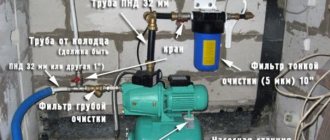
For a deep-well pump, it is also recommended to install a primary filter. For a surface pumping station, the fittings are attached to the suction pipe of the pressure blower, immediately behind the ratchet.
Plastic model in section. Source heat.guru
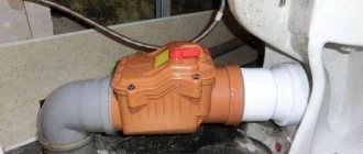
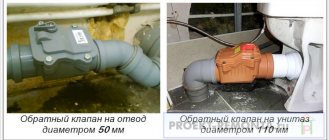
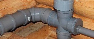
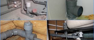
Return valve for sewerage
To prevent the flow of waste from being disrupted and circulating in the opposite direction, experts recommend installing a check valve on the sewer pipe. Such a valve will become an indispensable assistant in everyday life for all types of premises, as well as in production, since at the right time it will close the hole in the outlet sewer pipe.
Sewage return valve. Source orgtorg.org