Design Features
The difference between the 1341 turret lathe and universal type lathes is the absence of a tailstock and a lead screw. This is compensated by the presence of a caliper and a head with a turret arrangement of the tool. The head is used by placing a set of cutting tools in its sockets.
Fastening their various types in each of the sockets is possible using specific multi-tool holders. Adjustment (using a holder) ensures that the size specified in the drawing is obtained.
The type of machines includes turret heads with an axis of rotation:
- horizontal (1341);
- vertical.
The vertical axis of the head requires additional installation of a transverse support.
Adjustment of the tool stroke is provided by adjustable cams, which automatically switch off the feed. The presence of replaceable tools reduces processing time.
Design and purpose of the main components of the turret lathe model 1341
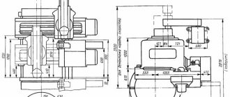
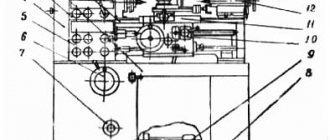
The appearance and main components of the turret lathe, presented in the laboratory work by model 1341, are shown in Figure 1.37.
Rice. 1.37. Turret lathe model 1341 ( a
) and its turret (
b
)
The machine has a horizontal axis of rotation of the turret head. It can process both bar and piece workpieces. The maximum diameter of a rod-shaped workpiece is 40 mm, and a piece workpiece is 400 mm.
The machine bed consists of a base 1
and the upper part
2
, on which are fixed: a headstock
3
with a gearbox and a spindle
5
, an electrical cabinet
10
, a bracket
7
with a tracing ruler for turning cones, a command device
12
for automatically changing the spindle speed and the tool feed rate.
There is a support on the longitudinal guides of the upper part of the frame 9
, carrying a turret
8
having a horizontal axis of rotation, a rear drum of stops
11
and a drum
13
with adjustable cams.
The cams, by placing them in a certain position when setting up the machine, provide the required switching sequences and the required values of the rotation speed of the spindle 5
of the machine and the feed of the support
9
for each of the tools located in the turret.
Here, on the frame, there is a circular feed limiter 15
(Fig. 1.37,
a, b
), ensuring that the circular movement of the turret is turned off.
16
is fixed on the left side of the machine bed. The working movements on the machine are: rotation of the spindle (main cutting movement Dg
), the movement of the longitudinal feed of the support
DSpr
and the circular movement of the feed of the turret
DScr
around the horizontal axis of rotation (used when it is necessary to create transverse feed movements
DSop
of the cutting tool (Fig. 1.37,
b
)).
Threading work on the machine is performed using taps and dies installed in the turret head, as well as a threaded comb attached to the tilting mechanism 6
. This mechanism ensures that the thread comb is pressed against the workpiece and imparts movement to the tool in the longitudinal direction with a feed equal to the pitch of the thread being cut.
In conditions of mass production, the turret lathe model 1341 has higher productivity than a screw-cutting lathe that is similar in power and characteristics of processed workpieces. This is achieved by the following design features of the machine.
Turret 8
on its end surface it has 16 holes (sockets)
17
(Fig. 1.37,
b
), the axes of which lie on a circle with diameter
D.
The top point of this circle is at the height of the machine spindle axis. One or more tools can be secured in each turret socket using auxiliary tools (tool holders, adapter bushings, drill chucks). All tools are installed in the turret when setting up the machine to process a batch of workpieces. Due to the large number of tools, setting up the machine takes quite a long time. However, this allows you to produce complex shaped parts without changing tools and reduces wasted time. For the same reason, using the machine when processing small batches of workpieces turns out to be unprofitable.
On the model 1341 machine, there is no need to spend time on adjustments and control of the resulting dimensions when moving from processing one workpiece to another. This is achieved by having devices with stops on the machine and installing (adjusting) the stops in a given position when preparing the machine for operation. The stops are located on the rear stop drum 11
, front drum
16
, on the turret
18
(Fig. 1.37,
a
,
b
).
The system of stops also includes a circular feed limiter 15
with a retractable pin
19.
Each socket
17
of the turret with a cutting tool corresponds in the system of stops to one or two (for transverse movement of the tool) stops, which, when setting up the machine, are installed in such a way that they ensure repetition of the execution by this tool one or more sizes on each blank of the manufactured batch.
Rear drum stops 11
serve to automatically shut off the movement of the longitudinal feed of the turret caliper. This is necessary to ensure the specified longitudinal dimensions on the workpiece when making transitions to turning external or internal surfaces and working with an axial tool. The diametrical dimensions obtained by longitudinal turning ensure adjustment of the extension of the cutters from the tool holders.
Front drum stops 16
fixes the position of the longitudinal support (the position of the tool relative to the workpiece in the longitudinal direction) when cutting with tools operating with a circular feed movement (cutting the end, turning grooves or shaped surfaces, cutting the workpiece).
When performing a specific transition to the corresponding stop of the drum 16
, the caliper is moved manually.
To turn off the circular feed movement and obtain a given diametrical size of a groove or shaped surface, adjustable stops 18
, which are installed on the turret (Fig. 1.37,
b
).
Saving time on a turret lathe in relation to processing workpieces on a screw-cutting lathe is also achieved by the fact that changing the spindle speed and feed rate to perform subsequent transitions is carried out simultaneously with changing the cutting tool due to the joint rotation of the turret head and the one mounted on it. command apparatus 12
with drum
13
. On this drum, when setting up the machine, by means of a certain arrangement of cams, a program for switching spindle speeds and feed values is typed.
Spindle speeds and feed speeds on the 1341 machine are divided into two ranges. On technological transitions, where it is necessary to switch from one range to another, the time spent increases, since such switching, performed manually by a switch on the control panel of the headstock of the machine, requires some additional time in relation to automatic switching.
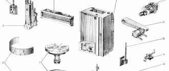
Reducing the time spent directly on removing chips when working on a turret lathe is also achieved by using multi-tool holders (Fig. 1.38), which ensure simultaneous processing of several surfaces of the workpiece in one working stroke of the caliper. The processing time at the transition with the simultaneous use of several tools is determined by the duration of processing of the longest surface being processed in the direction of feed movement. The cutting mode parameters in this case are assigned according to the most loaded tool.
The design features of the machine outlined above, aimed at increasing processing productivity in mass production conditions, led to a limitation of its technological capabilities in relation to the similar characteristics of a screw-cutting lathe. Thus, due to the absence of a tailstock, processing of shafts in the centers is impossible here, the length of the processed workpieces is limited, and long conical surfaces cannot be made. Due to the absence of a lead screw and a kinematic chain of thread feeds, the possibility of cutting precise threads and threads with a deep profile on the machine is excluded.
Rice. 1.38. Multi-tool setups
Components of model 1341
On the 1341 turret lathe, parts are processed in automatic and semi-automatic modes. Semi-automatic mode is used when processing piece workpieces. They are secured manually with three chuck jaws. In automatic mode, a steel rod is used, fixed with a collet-type chuck. The rod is secured by a hydraulic device.
Kinematic diagram of turret lathe 1341
The most important components of the 1341 machine include:
- lower and auxiliary beds;
- boxes: speeds;
- innings;
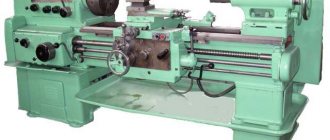
Appearance of machine 1341
RETURN LATHE 1341
The 1341 machine is a universal turret lathe. It can be rod or cartridge, and it can be used to perform work that requires the sequential use of various cutting tools (rough and finishing turning, drilling, boring, countersinking, reaming, threading, etc.).
Machine 1341 refers to turret machines with a horizontal axis of the turret head. The axis of rotation of the head is located 100 mm below the spindle axis and parallel to it. The turret has sixteen holes in which the cutting tool is secured using holders. This machine does not have a side (transverse) support. The turret head receives longitudinal and transverse (circular) feeds. The 1341 machine has devices that distinguish it from most turret lathes: a) a command device that automatically turns on the rotation speed and feed required for each transition when the turret head is turned; b) hydraulic mechanism
Figure 63. General view of the machine 1341
feeding and clamping of the rod, allowing the use of rods with a diameter deviation of 1 mm, as well as clamping piece workpieces with a diameter deviation of up to 8 mm in a three-jaw chuck; c) a copy ruler that allows you to process conical surfaces; d) a thread-cutting device that allows you to cut threads using threaded reels (copiers) with a pitch equal to or 2 times smaller than the pitch of the installed copier.
Settings
The machine is set up by starting a series of identical parts. It provides:
- development: part manufacturing technology;
- setup cards;
- spindle speed;
Basic elements of beds
The following is fixed to the main or lower frame:
- cast trough for coolant;
- auxiliary frame with guides for placing and moving the caliper;
- gearbox with spindle;
- gearbox;
- electrical cabinet;
- thread cutting device;
- copying device:
- container for oil used by the hydraulic drive;
- spindle and pump electric motors;
- box for collecting shavings.
General view of the turret lathe 1341
A carbon ruler is mounted on a bracket on the auxiliary frame. The folding stop is located on the right side of the caliper. It is designed to shut off the supply. Its transition to the working or neutral position is carried out using the handle.
Caliper
The caliper moves along the guides of the auxiliary frame using a rack and pinion.
The support contains:
- turret;
- command apparatus;
- stop drum;
- apron.
The head is attached to a shaft located on the caliper. The shaft rotates on ball bearings. The tool is secured into the head holes using holders. The holders provide rigidity of fastening, accuracy of installation and adjustment of the tool.
The same shaft is used to attach the command device and the stop drum. The head rotates after each working stroke, feeding the next tool to the processing zone. The command device ensures automatic activation of the required spindle speed and feed values corresponding to this type of tool.
Behind the command device there is a stop drum, which ensures automatic stop of the caliper when the required amount of tool movement is reached. The feed is switched off by cams installed in the grooves of the drum when they reach the folding stop.
Turret lathe 1341
Through the action of the cams, the activation of the specified electromagnetic clutches in the gearboxes and feeds is ensured. This allows you to obtain the spindle speed and feed values specified for this operation.
REVOLVER LATHE 1341;
The 1341 machine is a universal turret lathe.
It can be rod or cartridge, and it can be used to perform work that requires the sequential use of various cutting tools: rough and finishing turning, drilling, boring, countersinking, reaming, threading, etc. The 1341 machine belongs to turret machines with a horizontal axis rotation of the turret head. The axis of rotation of the head is located 100 mm below the spindle axis and parallel to it. The turret has sixteen holes in which the cutting tool is attached using holders. This machine does not have a side (transverse) support. The turret head receives longitudinal and transverse (circular) feeds.
The 1341 machine has devices that distinguish it from most turret lathes:
a) a command device that automatically turns on the rotation speed and feed required for each transition when turning the turret;
b) a hydraulic rod feeding and clamping mechanism, which allows the use of rods with a diameter deviation of ±1 mm, as well as clamping piece workpieces with a diameter deviation of up to 8 mm in a three-jaw chuck;
c) a copy ruler that allows you to process conical surfaces;
Rice. 124. General view of machine 1341
d) a thread-cutting device that allows you to cut threads using threaded reels (copiers) with a pitch equal to or 2 times smaller than the pitch of the installed copier.
Characteristics of the machine (Fig. 124). The maximum diameter of the processed rod is 40 mm; largest diameter of the workpiece clamped in the chuck: above the frame - 400 mm, above the caliper carriage - 380 mm; number of spindle rotation speeds—8 (60–2000 rpm); number of cross feeds -8 (0.03-0.48 mm/rev); number of longitudinal feeds - 16 (0.05 - 1.6 mm/rev); maximum length of thread to be cut is 50 mm; overall dimensions 3000 X 1200 X 1560 mm.
Movements in the machine. The main movement - rotation of the spindle (Fig. 125,a) is carried out from an electric motor (N = 4.5 kW, n = 1440 rpm) through a gearbox. Various spindle speeds are activated by switching four electromagnetic clutches M1-M4 and block B1.
Kinematic chain equation for minimum spindle speed:
rpm
The spindle is braked when stopping by simultaneously turning on the M3 and M4 clutches with the main motion drive electric motor running and the cell clutches turned off. When clutches M3 and M4 are engaged simultaneously, two gears are engaged from shaft III to shaft IV with different gear ratios, as a result of which the spindle is braked.
The longitudinal feed of the turret support is carried out from the spindle V through a series of intermediate gears, a feed box and a rack and pinion pair. Equation of the kinematic chain of minimum longitudinal feed:
Various feed stages are activated by switching four electromagnetic clutches M5-M8 and blocks B2 and B3. Electromagnetic clutches are switched either automatically from the cams of the command device, or manually using a handle. Blocks B2 and B3 are switched by handles.
Mechanical longitudinal feeds are activated by the M9 clutch, which transmits rotation from the worm wheel z = 33 to the gear wheel z = 25. Longitudinal movements of the turret support are manually carried out by steering wheel 1 with the M9 clutch turned off.
Transverse (circular) feed is carried out from the machine spindle to the running shaft along the same kinematic chain as with longitudinal feed, and then through a couple of
bevel gears, a bevel reversing mechanism (z = 22, z = 22, z = 22), a worm pair and a gear drive to the turret, during rotation of which a transverse (circular) feed occurs. To carry out transverse (circular) feeding, you need to turn on the M10 gear clutch with the handle and the M11 electromagnetic clutch with the switch.
Equation of the kinematic chain of the minimum transverse (circular) feed:
where R is the radius of the circle of the centers of the tool pockets in mm (for this machine R = 100 mm).
Transverse feeds of the turret head are manually carried out by handwheel 2 with the middle (off) position of the M10 gear coupling and the M11 electromagnetic clutch on.
Quick rotation of the turret to the next working position is carried out manually. To do this, you need to turn off the M11 clutch and manually rotate handwheel 3. In this case, the turret head lock is released in advance.
The thread-cutting device is designed for cutting external and internal threads of various pitches using cutters or combs using a copier 4 (Fig. 125.6).
From the spindle via a kinematic chain with a gear ratio
or the rotation is transferred to a replacement copier. With a gear ratio i2 = 1, the pitch of the thread being cut is equal to the thread pitch of the installed copier 4, and with a gear ratio - half of this pitch.
To cut the thread, you need to lower the lever 5 until the screw of this lever stops in the bar 6. Together with the lever 5, the caliper 7 and the lever 8 with the threaded jaw 9 and a weight attached to it rotate. In this case, the threaded comb mounted on the support takes the position required for cutting threads, and the threaded jaw 9, moving along the thread of the copier 4, will move the rod 10, lever 5 and support 7 in the axial direction, ensuring longitudinal feed of the tool per step of the thread being cut .
The amount of longitudinal movement of the caliper 7 is limited by a stop, which is attached to the lever 5. As a result of the action of the stop, the lever 5 and the jaw 9 rise above the thread of the copier 4 and the rod 10, under the action of the spring 11, returns again to the right position. Thread cutting occurs in several passes. Before each subsequent pass, the thread comb must be fed in the transverse direction.
The copy ruler is designed for longitudinal or transverse copying. To do this, a special holder with a roller is attached to the turret head, which rests on the surface of the copy ruler. The copying ruler is installed at the required angle to the horizontal and secured in this position.
Longitudinal copying is carried out with longitudinal feed of the turret support. In this case, the holder roller moves along an inclined ruler and rotates the turret head along with the cutter around its axis, imparting a transverse feed to it. The roller is pressed against the surface of the copy ruler by the cutting force. When the cutter simultaneously performs longitudinal and transverse feeds on the part, a conical or other shaped surface is formed.
For cross-section copying, the copying ruler is replaced by a T-shaped copying ruler. During transverse copying, the transverse feed is turned on, and the longitudinal movement of the caliper occurs under the action of the copying ruler due to the fact that the roller moves along its T-shaped part.
Stop drum. To automatically switch off the longitudinal feed, the machine has a stop drum 15 with sixteen (according to the number of positions of the turret) T-shaped grooves and six annular grooves. In each of the T-shaped grooves, a cam 12 can be attached (Fig. 125, e), which serves to turn off the longitudinal feed of the turret caliper in its left position. When installing each tool into the working position, the caliper feed is turned off using the cam 12, which is located at this time on the underside of the stop drum. Screw 13 of cam 12 stops the caliper using a folding stop 14.
At the end of the stroke of the revolving support to the left, the cam 12 of the stop drum, which is currently in the lower position, rests with a screw 13 against the folding stop 14 and stops the support in this position. In this case, the rotation of the rack and pinion gear z = 16 of shaft XIII, gear wheels z = 68 and z = 25, coupling M9 and worm wheel z - 33 stops, and the worm k = 1 continues to rotate on shaft XI. The rotating worm rests with its turns against the teeth of a stationary worm wheel z = 33 and moves along the splines of the XI shaft to the left. Compressing spring 37, through a special device, it turns off the M9 clutch and, therefore, turns off the longitudinal feed.
To activate the feed switching mechanism, handle 16 must be turned toward you. In this case, the axis 17, using the key 18, will rotate the stop 14 to the position shown in the diagram, and the ball 19, under the influence of the spring 20, will enter the seat 21, holding the stop 14 in the upper working position.
Spindle assembly
Spindle speed and feed rates are adjusted for control modes:
- Automatic - a command device that is configured in advance to perform the technological process. Its design allows you to give a control impulse to the electromagnetic clutches used to switch gears (located in the gearbox).
- Manual - using the toggle switches located on this box.
The spindle unit provides feeding/fastening of the rod using a hydraulic device using a collet.
Clamping/unfastening of bar stock is carried out automatically, piece workpiece is done manually. The part obtained from the bar is cut off, and the turret is returned to the starting position to adjust the length of the other part along the stop.
1P365, 1P371 Turret lathe. Purpose, scope
1P365 turret lathe 1365 in mass production
and was replaced by a more advanced model
1M365
.
Universal turret lathes 1P365 and 1P371 are designed for high-performance processing of various parts made of cast iron, steel and non-ferrous metals with tools made of hard alloys and high-speed steel, parts from piece workpieces (forgings, stampings, castings, etc.) with a diameter of up to 500 mm and from rod with a diameter of up to 80 mm.
1P365 machines are designed for processing piece workpieces in a chuck with a maximum processing diameter of 500 mm over the bed, the production of which requires a number of sequential transitions: turning, drilling, boring, reaming, threading, etc. in mass production conditions.
The machines can perform roughing and finishing turning, boring, drilling, countersinking, reaming and threading with special devices.
Design features and operating principle of the 1p365 machine
Turret lathes 1P365 and 1P371 have a turret support with a hexagonal turret head with a vertical axis of rotation. Bridge type transverse support with front square head and rear tool holder for one tool. Several cutters can be installed in a special tool holder.
The workpiece is secured in a conventional self-centering or pneumatic chuck. The entire set of cutting tools necessary for this operation is installed in a six-position turret and in a four-sided tool holder of the caliper.
On the 1P365 , a part can be processed in six positions. Parallel operation of tools installed in the turret and tools installed in the tool holder of the caliper is possible.
The tool and caliper travel limiters (stops) are installed in such a way that the workpiece receives the specified dimensions after processing.
The layout of the units is generally accepted for this standard size of universal turret machines. All gearbox and feed box controls are hydraulic. The choice of spindle speeds and feed rates on all models is preselective.
Switching spindle speeds and feed rates occurs when the gears are slowly turned.
The machine bed has a rigid structure with flat guides. It is mounted on two pedestals, on which a trough is installed to collect chips and coolant. The trough has two tanks: one for hydraulic oil and lubricant, the other for coolant. The electric motor of the main drive of the machine is mounted in the left cabinet of the frame. The rear wall of the frame has two windows for free release of chips.
Copy
The 1341 turret lathe has mechanisms used for thread cutting and copying.
They use a thread cutting mechanism on a copier thread blank using a thread comb. This technology involves multiple passes to obtain a complete thread profile. The device is located in the gearbox housing. Its drive is driven by gears from the spindle.
Another copier has a copying ruler, which is used for longitudinal and transverse copying. In this case, conical and shaped surfaces are obtained. Shaped surfaces are obtained by installing a curved template instead of a carbon ruler.
In the longitudinal direction of copying, the support moves to the spindle assembly, and the turret rotates, repeating the profile of the copier.
Equipment technical parameters
The dimensions of parts manufactured on the 1341 machine are determined by its parameters. These include dimensions (mm):
- workpieces: when using a cartridge – 400;
- above the caliper – 380;
- round – 40;
The dimensions of the machine are 3.0 * 1.2 * 1.6 m. Its weight is 2200 kg.
Electrical diagram of turret lathe 1341
The electric motor that rotates the spindle has a power of 5.5 kW. The number of speeds used by the machine is 8 (from 60 to 2000 rpm). In addition, there are electric motors:
- hydraulic drive for clamping and advancing the rod (1.1 kW);
- cooling pump (0.125 kW).
The caliper moves 560 mm.
Technical characteristics of the machine 1P365
| Parameter name | 1E365BP | 1P365 | 1P371 |
| Basic machine parameters | |||
| Accuracy class according to GOST 8-82 | N, P (1E365BP) | N | N |
| The largest diameter of the workpiece above the bed, mm | 500 | 500 | 630 |
| The largest diameter of the workpiece above the transverse slide, mm | 330 | 320 | 420 |
| Center height, mm | 250 | 250 | 315 |
| Distance from the end of the spindle to the turret, mm | 270..1000 | 275..1000 | 320..1400 |
| Spindle | |||
| Spindle hole diameter, mm | 80 | 80 | 125 |
| Diameter of the processed rod clamped in the supply pipe (rod version), mm | 65 | ||
| Diameter of the processed bar with front clamping (bar version), mm | 80 | ||
| Chuck diameter, mm | 250 | ||
| Number of spindle speeds | 13 | 12 | 12 |
| Spindle speed limits, rpm | 24..1500 2 ranges | 34..1500 | 20..893 |
| Spindle speed limits (reverse rotation), rpm | 67 | 34..1500 | 19..818 |
| The end of the spindle is flanged according to GOST 12595-72 | 1-8C | 1-8C | 1-8C |
| Maximum torque on the spindle, not less than, Nm (kg*m) | 123 | 260 | |
| Turret caliper | |||
| Number of tools in turret | 6 | 6 | 6 |
| Diameter of the hole for the tool in the turret, mm | 95N7 | 95N7 | 125N7 |
| Maximum longitudinal movement of the turret caliper, mm | 730 | 725 | 1080 |
| Number of feed stages | 13 | 13 | 13 |
| Speed range of longitudinal feeds of the turret caliper, row 1, mm/rev (number of feeds) | 0,05..0,80 (9) | 0,09..1,35 (9) | 0,09..1,35 (9) |
| Speed range of longitudinal feeds of the turret caliper, row II, mm/rev (number of feeds) | 0,10..1,60 (9) | 0,18..2,70 (9) | 0,18..2,70 (9) |
| Speed range of longitudinal feeds of the turret caliper, row III, mm/rev (number of feeds) | 0,20..3,20 | — | — |
| Speed of rapid longitudinal movement of the turret caliper, m/min | 7,5 | 6 | 6 |
| Number of turret support stops | 6 | 6 | 6 |
| Movement by one division of the dial, mm | 0,2 | 0,2 | 0,2 |
| Movement per one revolution of the dial, mm | 45 | 45 | 45 |
| Cross caliper | |||
| Number of cutters in the tool holder | 4 | 4 | 4 |
| Number of cutters in the rear tool holder | 1 | 1 | No |
| Maximum movement of the transverse support longitudinal/transverse, mm | 730/ 310 | 725/ 310 | 1080/ 410 |
| Number of stages of longitudinal feed of the transverse caliper | 13 | 12 | 12 |
| Speed range of longitudinal feeds of the turret caliper, row 1, mm/rev (number of feeds) | 0,05..0,80 (9) | 0,09..1,35 (9) | 0,09..1,35 (9) |
| Speed range of longitudinal feeds of the turret caliper, row II, mm/rev (number of feeds) | 0,10..1,60 (9) | 0,18..2,70 (9) | 0,18..2,70 (9) |
| Speed range of longitudinal feeds of the turret caliper, row III, mm/rev (number of feeds) | 0,20..3,20 | — | — |
| Number of stages of transverse feed of the transverse caliper | 13 | 12 | 12 |
| Speed range of transverse feeds of the transverse caliper, row 1, mm/rev | 0,025..0,40 | 0,045..0,7 | 0,045..0,7 |
| Speed range of transverse feeds of the transverse caliper, row II, mm/rev | 0,05..0,80 | 0,09..1,35 | 0,09..1,35 |
| Speed range of transverse feeds of the transverse caliper, row III, mm/rev | 0,10..1,60 | — | — |
| Speed of rapid longitudinal movement of the caliper, m/min | 7,5 | 6 | 6 |
| Speed of fast transverse movement of the caliper, m/min | 3,5 | — | — |
| Number of longitudinal movement stops | 5 | 5 | 5 |
| Number of cross movement stops | 2 | 2 | 2 |
| Movement of one dial division longitudinal/transverse, mm | 0,2/ 0,05 | 0,2/ 0,05 | 0,2/ 0,05 |
| Longitudinal/transverse movement of the dial per one revolution, mm | 45/ 4 | 45/ 10 | 45/ 10 |
| Electrical equipment of the machine | |||
| Number of electric motors on the machine, kW (rpm) | 3 | 2 | 3 |
| Main drive electric motor, kW (rpm) | 15 (1465) | 13 (1450) | 22 (1460) |
| Hydraulic drive electric motor, kW (rpm) | 2,2 (1430) | — | 1,5 (930) |
| Cooling pump electric motor, kW (rpm) | 0,125 (2800) | 0,125 (2800) | 0,125 (2800) |
| Dimensions and weight of the machine | |||
| Overall dimensions of the machine (length, width, height), mm | 4400 x 1525 x 1800 | 3430 x 1500 x 1655 | 4230 x 1850 x 1680 |
| Machine weight, kg | 5200 | 3900 | 6300 |
- Turret lathes 1P365, 1P371. Operating manual, 1982
- Volkevich L.I., Kuznetsov M.M., Usov B.A. Automatic machines and automatic lines, 1976
- Zazersky E.I., Mitrofanov N.G., Sakhnovsky A.G. Handbook for a young operator of automatic and semi-automatic lathes, 1987
- Itin A.M., Rodichev Yu.Ya. Setup and operation of multi-spindle semi-automatic lathes, 1977
- Kamyshny N.I., Starodubov V.S. Design and adjustment of automatic and semi-automatic lathes, 1975
- Lisova A.I. Construction, adjustment and operation of metalworking machines and automatic lines, 1971
- Pozhitkov A.Ya., Safro I.D. Setting up single-spindle automatic lathes. Reference manual, 1978
- Pronikov A.S. Metal-cutting machines and automatic machines, 1981
- Feshchenko V.N. Processing on turret lathes, 1989
- Fomin S.F. Construction and adjustment of turret lathes, 1976
Bibliography:
Related Links. Additional Information
- Classification and main characteristics of turning
- Selecting the right metalworking machine
- Multi-start thread. Methods for cutting multi-start threads on a lathe
- Graphic signs for lathes
- Friction clutch of a screw-cutting lathe
- Methodology for checking and testing screw-cutting lathes for accuracy
- Directory of lathe manufacturing plants
- Directory of factories producing metal-cutting machines
- Directory of lathes
- Articles on the topic
Home About the company News Articles Price list Contacts Reference information Interesting video KPO woodworking machines Manufacturers
Documentation for the machine
The manufacturer of the turret lathe 1341 is the Berdichev machine tool. The equipment is supplied with technical documentation. One of the fundamental documents is the passport, which is a guide for the turners and mechanics who operate it.
Download the passport (operating instructions) of the turret cutting machine 1341
The passport provides for reflection of the following points:
- requirements for packaging and transportation;
- purpose and principle of operation of the machine;
- operational and technical characteristics;
- compliance with the requirements during commissioning;
- Availability of specifications: for machine control;
- bearings;
- electrical equipment;
- hydraulic mechanisms;
Machine passport 1V340F30
This operating manual “ Passport of the machine 1V340F30 ” contains information necessary both for the maintenance personnel of this machine and for the employee directly involved in working on this machine. This manual is an electronic version in PDF format of the original paper version. This documentation contains a Passport and a Manual (instructions) for operating the 1V340F30 turret lathe.
CONTENT
General information about the product
- Purpose and scope
Basic technical data and characteristics
- Machine Specifications
- Machine mechanics
- Technical characteristics of electrical equipment
- Technical characteristics of the hydraulic equipment and lubrication system of the machine
- Technical characteristics of the numerical control device
Safety instructions
- For service personnel
- When transporting and installing the machine
- When preparing the machine for operation
Product composition Design and operation of the machine and its components
- List of controls
- List of graphic symbols indicated on the remote control and signs
- Kinematic diagram of the machine
- Main movement
- Feed movement
- Node design
- bed
- Main drive
- Clamping and material feeding mechanism
- Spindle head
- Revolver caliper
- Cutting support
- Drive of longitudinal feeds of the turret caliper
- Transverse feed drive of the turret caliper
- Lock block
- Racks
- Unloading mechanism
Electrical equipment
- General information
- Electrical power supply system
- Basic electrical data
- Brief description of the operation of the machine's electrical automation
- Instructions for initial start-up of the machine
- Local lighting
- Signaling
- Locks
- Protection
- Instructions for necessary adjustments
- Thyristor drive system
- Features of working with CNC "Electronics NTs31-01"
- Practical programming tips
- Instructions for using electrical equipment
- Safety instructions
- General requirements
- Machine connection
- Safety precautions when servicing the machine
- Instructions for carrying out preventive repairs of the machine and electrical equipment
- Instructions for safety measures for working with CNC "Electronics NTs31"
- Instructions for safety measures when setting up the main drive and high-torque feed drives
Hydraulic system of the machine
- Tank
- Pumping unit
- Hydraulic control unit
- Hydraulic diagram of the machine 1V340F30
- Purpose
- Circuit operation
- Clamping-unclamping of the product
- Cutting caliper
- Unloading mechanism
- Turret caliper
Lubrication system
- Installation procedure
- Unboxing
- Installation
Features of disassembly and assembly when repairing a machine
- Disassembling the spindle assembly
- Disassembling the clamping and material feeding mechanism
Adjusting tension belts Spare parts materials
- Bearing layout
Acceptance information Storage Operating instructions
- Regulation
- Adjusting the support gap outside the machine
- Adjustment of the clamping mechanism and material feeding
Warranty obligations Sketches of accessories
download the passport of the 1V340F30 turret lathe in normal quality using the link below.
conclusions
- Turret lathes provide a reduction in technological time when using turret heads with a set of tools.
- Setting up and correct sequence of tool installation allows you to reduce the transition time from one processing operation to another, increasing labor efficiency.
- Machines 1341 allow you to produce parts of complex shapes, thanks to the presence of different types of tools.
- Model 1341 provides normal precision in manufacturing parts.