General provisions
1.1 This instruction is intended to ensure high-quality laying, installation and commissioning of optical cables produced by Incab LLC (hereinafter referred to as the optical cable).
1.2 The purpose of this instruction is to provide conditions for uninterrupted operation of the optical cable throughout its entire service life.
1.3 The instructions are mandatory for all organizations involved in the laying, installation and operation of optical cables. Organizations installing optical cable must have appropriate licenses.
Basic regulatory documents
2.1 Guidelines for the construction of linear structures of trunk and intrazonal cable communication lines. .- M. 1986
2.2 Guidelines for the construction of local network structures. /Ministry of Communications - M. 1996.
2.3 Manual for the operation of line-cable structures of local communication networks. - M. 1998
2.4 RD 45.120-2000 Technological design standards. Urban and rural telephone networks.
2.5 R 50-601-40-93. Recommendations. Incoming control. Basic provisions. – M. 1993
2.6 Installation and electrical measurements of line-cable communication structures. KTE24-1-97. – M., 1997
2.7 Rules for commissioning communication structures. Approved by order of the Ministry of Communications 09.09.2002. – St. Petersburg: 2002
2.8 Rules for electrical installations. In the 7th edition.
2.9 RD 45.190-2001 Elementary cable section of a fiber-optic transmission line. Standard acceptance test program.
2.10 Labor protection rules when working on cable communication lines and wire broadcasting (radio) POT R O-45-005-95
What it is
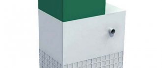
First of all, such a system is special underground communications, united into one network of containers, as well as channels where various types of cables are located.
These are pipes where they are directly laid and wells, using which they are inspected, replaced or other manipulations are carried out.
In some cases, cables are laid openly, so no piping is used. Here they are replaced by the basements of various structures, tunnels and the collectors themselves. The cable lines themselves are strengthened using special devices.
Such communications are needed to ensure proper protection of wires from the impact of earth, asphalt, and various atmospheric phenomena on them. At the same time, to repair or replace cables, there is no need to destroy the road surface or remove soil.
However, in our country, cable ducts laid in the same way as the pipeline are more popular.
To install them, trenches of the required size are dug in advance. At the same time, installation can also be carried out using trenchless technology, when the cables are located above the ground. The advantage of this option is that there is no need to disturb the integrity of the soil.
Various cable duct options have certain differences in size and shape, as well as the materials used for their manufacture. So, wells can be made of reinforced concrete, brick, or even plastic. Such systems use pipes made of concrete, fiberglass, asbestos and even plastic.
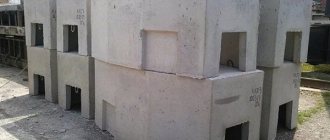
It is worth noting: the most popular options from the above are plastic and asbestos. Sometimes, instead of pipes, special blocks are used, which are called multichannels.
Incoming control
3.1 The following is a list of recommended incoming inspection tests.
3.1.1 Quality of cable winding. Check the quality of winding of the finished cable on the receiving drum. The winding of turns should be even. The take-up drum must not have any visible damage.
3.1.2 Cable appearance. Check the appearance of the cable visually for defects.
3.1.3 Construction. Carry out cable cutting in accordance with paragraph 7 of these instructions. Check the presence of structural elements stated in the specification for the cable.
3.1.4 Total number of OBs. Check that the actual number of optical fibers matches that stated in the cable data sheet.
3.1.5 Cable marking. Check the presence and quality of markings on the cable.
3.1.6 Construction length of the cable. Check that the actual cable length corresponds to the value in the passport (by marking).
3.1.7 External diameter of the cable. Check that the actual outer diameter of the cable matches the value stated in the cable passport.
3.1.8 Attenuation coefficient. Measure the attenuation coefficient of optical fibers at wavelengths of 1310 and 1550 nm (for multimode OF at a wavelength of 1300 nm), its value should not exceed the declared value.
3.1.9 Length and integrity of the agent. The fiber length must correspond to that indicated in the passport. Integrity must not be compromised.
3.1.10 For a cable with metal armor, electrical resistance of the “armor-ground (water)” circuit GOST 3345-76
Basic requirements for transportation and storage
4.1 During transportation, drums should not lie on the cheek and should be securely fastened. When fastening drums, it is prohibited to pierce the cheek boards and drum casing with nails and staples.
4.2 The optical cable must be transported only on the manufacturer's drum.
4.3 When loading (unloading) drums, it is necessary to use special equipment to prevent impacts and mechanical damage to the drums. It is prohibited to throw drums off the vehicle or roll them down hills.
4.4 After transportation, drums must be checked for damage and integrity of protective devices.
4.5 During storage, drums must be protected from mechanical influences, as well as from sunlight, precipitation and dust. The drums should not rest on the cheek. It is not allowed to install drums on top of each other (Fig. 1). Storage temperature: from minus 60 ºС to 70 ºС. The ends of the optical cable during storage must be protected using special sealing heat-shrinkable caps.
4.6 The drum casing is removed only after the start of work, after installing the drum on the device for winding the cable from the drum, with the permission of the responsible work manager.
Rice. 1. Storing optical cable reels
Before laying
5.1 Preparation of cable ducts for laying optical cable includes: installation of fences, preparation of wells, preparation of cable ducts, preparation and cleaning of cable ducts and, if necessary, laying of an auxiliary pipeline (polyethylene pipes).
5.2 Work in cable ducts for laying cables must be carried out in strict compliance with the requirements of the current “Occupational Safety and Health Rules when working on cable communication lines and wire broadcasting”, the main of which are: fencing open wells and work areas, checking wells for the presence of hazardous gases, ventilation of wells, taking precautions in the presence of cables with remote power supply voltage and wire broadcasting cables in wells. Personnel who have completed a training course in technological rules and work methods are allowed to carry out work.
5.3 In accordance with safety requirements, fences - barriers - are installed near the wells being opened on both sides. On the roadway, fences should be installed on the side of traffic at a distance of at least 2 m from the well hatch. In addition, warning signs must be installed at a distance of 10–15 m from the fence facing traffic. In case of poor visibility, additional light signals must be installed. Before starting work in wells located on the roadway, it is necessary to notify the local traffic police authorities about the place and time of the work.
5.4 To prevent accidents and damage, wells must be opened using appropriate devices, for example, lid lifters, lifting pliers. Under no circumstances should picks, shovels, hammers, crowbars, files or other metal tools be used. Firmly frozen lids can only be dislodged using wooden tampers without metal edging or a hot defrost device. The use of metal tools to remove snow and ice from manholes on wells is permitted only if this does not create a spark. Due to the risk of gas explosion, defrosting using an open flame is prohibited.
5.5 Before workers lower into the well, it is properly ventilated. To determine the presence of gas in the sewer, it is necessary to use a gas analyzer. No work should begin until the sewer is free of gas. If gas is detected, the work manager must be notified immediately. In the wells in which you are going to work, it is necessary to check the absence of gases: methane, propane and carbon dioxide. At least one channel (preferably the upper one) is temporarily opened, and after 10–15 minutes, a check is made again for the absence of harmful gases. If the well is being descended for the first time, a worker must remain outside, even if no gas was detected. A worker descending into a well should be secured with a rescue rope. When descending, do not step on cables, couplings or cable fastenings.
5.6 Channel selection
5.6.1 Laying optical cables in cable ducts should be carried out, as a rule, in free channels and located, if possible, in the middle of the block vertically and at the edge horizontally. No more than six optical cables can be laid in a free channel. It is not allowed to use a channel occupied by unarmored optical cables laid without protective polymer pipes for laying armored optical cables. The laying of unarmored optical cables in a cable duct occupied by cables with metal conductors and optical armored cables must be provided in pre-laid protective polyethylene tubes. Optical cables with armor made of fiberglass rods, steel wires and tapes with a protective polyethylene sheath on top of the armor can be laid both through free and occupied channels without being pulled into a polyethylene pipe.
5.6.2 It is allowed to lay several cables or protective polyethylene tubes in one channel, provided that the total cross-sectional area of the cables and (or) pipes does not exceed 0.6 of the channel area.
5.6.3 When laying optical cables in cable structures together with power cables, optical cables and power cables must be laid in separate channels; in the case when the cable structure does not have a dedicated channel for laying optical cables, the placement should be made only under or only above the power cables; however, they should be separated by a partition.
Dividing partitions must have a fire resistance rating of at least 0.25 hours.
5.7 Cleaning the channel.
5.7.1 If, as a result of penetration of groundwater into the canal, the canals in some places are filled with sand, clay, silt, etc., the canals must be cleaned. For cleaning, special steel scoops should be used.
5.7.2 It is recommended to remove ice formed in the channel using steam from a mobile steam generator. If cleaning the channels does not give positive results, then this section of the sewer should be opened and repaired. If necessary, inserts are made from sections of new solid or split pipes.
5.7.3 In the process of preparing the cable duct for cable laying, the permeability of the channels is checked. To do this, the test cylinder is connected with a carabiner to a special brush. The diameter of the test cylinder should be: 92 mm - for asbestos-cement and concrete pipes with a diameter of 100 mm, 82 mm - for asbestos-cement and concrete pipes with a diameter of 90 mm, as well as polyethylene pipes with a diameter of 100 mm.
5.7.4 If the test cylinder and brush pass through the channel with great difficulty, then they should be removed from the channel. It is advisable to replace the blank wire with a rope. The rope is attached on one side to a test cylinder, on the other side to a special brush. By dragging the cylinder and brush several times back and forth through a difficult place, the channel is cleared of contaminants.
Instead of a metal brush, a sand trap, a scraper on a steel tube, or a brush can be used.
Channels made of plastic pipes must not be cleaned with sharp-edged tools (such as steel wire brushes).
Cleaning tools and cable pulls are usually pulled through the duct manually by several people. If the cleaning device gets stuck, it is pulled back with a winch. If contamination is very high, multiple passes may be required and possibly flushing of the cable duct.
It is recommended to carry out comprehensive cleaning using a steel scoop. After cleaning the channel, the cylinder and brush are removed from the initial well. A blank wire is attached to the brush and again pulled through the channel along with the wire.
5.7.5 Cleaning of occupied cable channels should be carried out in ways that prevent damage to previously laid cables.
5.7.6 If subsidence of asbestos-cement pipes is detected at the joints (displacement of centers), then under no circumstances should a cable be laid in them. It is necessary to take measures to eliminate pipe subsidence and only then begin laying the cable.
5.8 Preparation of the channel when laying without protective pipes.
5.8.1 To lay a cable in a cable duct channel, you must first lay a steel wire with a diameter of 3 mm in it - make a channel blank. The channel is prepared in three ways: with metal sticks 1 m long, screwed together into a whip; polyethylene tube, up to 150 m long; glass rod, enclosed in a polyethylene shell, with an outer diameter of 11 mm and a length of up to 150 m, wound on a special vestibule, which ensures ease of working with the rods, preventing its spontaneous unwinding.
5.8.2 Preparing channels with metal sticks is done by pushing them into the channel, increasing them by screwing. When the first stick comes out of the adjacent well, a blank steel wire with a diameter of 3 mm is attached to its tail tip and the sticks are pulled out, unscrewing one at a time. On straight sections of the route or when preparing free channels, it is recommended to pass the sticks without unscrewing them through several wells while this movement is possible.
Sticks are recommended for use when preparing difficult-to-pass channels. When working with sticks, you should avoid spinning them in the channel. If unwinding has occurred, then to remove the string of sticks, you should use a special funnel to catch and screw the loose string into the channel.
5.8.3 Preparation of channels with a polyethylene tube is carried out by pushing, if possible, through all transit wells. In difficult sections of the route, workers provide auxiliary tightening of the tube. The blank wire should be attached to the tail tip and pulled along with the tube. If advancing the tube becomes impossible due to obstacles in the canal, it is recommended to turn the tube clockwise and counterclockwise several times while simultaneously pushing it into the canal.
5.8.4 The most effective way is to prepare channels using ultrasonic testing devices. In this case, the glass rod is pushed into the channel, unwinding it from the vestibule through the transit wells together with the blank wire attached to the tail tip (with the rod being tightened in the transit wells). If the mass of the optical cable is less than 0.3 kg/m, it is allowed to pull it into the channel with a glass rod.
5.9 Preparation of the channel when laying in protective pipes.
5.9.1 The protective polyethylene tube is laid from a coil installed at the well on a mobile vestibule, or from a coil manually. The end of the tube, equipped with a tip, is inserted into the channel and pushed forward along it along the entire length of the span(s). If there are transit wells, the tube is tightened.
If advancement of the tube becomes impossible due to obstacles in the channel, the tube must be rotated several times around its axis while simultaneously pushing.
5.9.2 In each well, the polyethylene tube is cut with a hacksaw, leaving a margin of 25 cm from the end of the channel. They do it as follows. At the entrance of the last well, an anti-theft device is installed on the tube, which is a stop that prevents the tube from moving when it is wired and laid (taking into account its direction).
Next, the pipe is fed back through the channel, cut off at the inlet of the next well and pushed back through the channel. Next, the tube is cut off at the outlet of the previous well and again pushed through the channel. This is done in every transit well.
5.9.3 If it is possible to lay the cable through transit wells without tightening, it is allowed not to cut the tube in these wells. In this case, it is necessary to provide a supply of pipe for laying it on the console.
5.9.4 Simultaneously with cutting the tube, one anti-theft device is installed at the channel inlet and outlet for the period of cable laying. In cases where the preparation of a laid polyethylene tube and laying of a cable are not carried out immediately, but after some time, during which the wells can be filled with water, to prevent sand, clay, and silt from entering the laid tubes, they are temporarily protected in each well with polyethylene caps with a winding around them joint with 5-7 layers of adhesive plastic tape.
5.9.5 The polyethylene tube is prepared using galvanized steel wire with a diameter of 3 mm or steel cable. If the inner surface of the tube is coated with a solid lubricant, then such a pipe must be prepared using means that will prevent damage to the solid lubricant. This is done in two ways - with a steleplastic rod or with a pneumatic drill. When laying a cable weighing up to 0.3 kg/m, it is allowed to prepare the tube with fiberglass rod.
5.9.6 Preparing a protective pipe with a pneumatic boring machine is recommended for spans from 80 to 150 m. This method can be used for preparing only clean, free channels and auxiliary pipelines from polyethylene tubes. Harvesting work using a pneumatic device is carried out by two workers. A rope winch and a charged cylinder of compressed air are installed at the head well (a compressor can be used). A torsion compensator is connected to the rope, and then the piston of the pneumatic harvesting device is attached. The piston is inserted into the prepared channel. An end plug is installed at the channel entrance, through which a rope is passed and a pneumatic line is connected. The assembled device is inserted all the way and the rubber seal is manually compressed to the maximum. Open the cylinder valve and set the operating pressure to 0.4–0.8 MPa using the pressure gauge. Then the lever of the pneumatic valve is sharply pressed, while air is supplied into the channel through a flexible hose. Under the influence of compressed air, the piston moves, pulling the rope into the channel. The end of the shot is determined by the weakening of the rope. After this, the pneumatic valve lever is released and the valve is closed. Then, using a rope, a wire or cable is pulled into the pipe.
Construction of telephone sewer
Construction of turnkey cable ducts, repair of channels of existing telephone ducts, restoration of damage (broken, not passed, silted, clogged) of telephone ducts, installation, repair, cleaning of telephone wells of various types, construction and restoration of telephone inputs, excavation work on cable routes, restoration of landscaping - all this work is one of the main directions of our company.
Having our own specialized construction equipment (excavators, manipulators, dump trucks), experience and appropriate qualifications allows, in conditions of fairly high competition, to successfully participate in commercial tenders, as well as in government procurement under Federal Law-223, Federal Law-44.
As a full-cycle Contractor , LLC "GUP KOMSTEK" carries out not only construction and installation work , but also the supply of all necessary components for the construction and repair of cable telephone sewer systems , such as pipelines, wells, road slabs, blocks and other related products and materials, as well as the supply of non-metallic bulk materials (sand, crushed stone, gravel).
LLC "GUP KOMSTEC" carries out the construction of line-cable communication structures (LCS) not only in the interests of the majority of leading telecom operators, such as PJSC MGTS, PJSC Rostelecom, KP MPTC, PJSC VimpelCom, JSC Voentelecom, PJSC Megafon, PJSC MTS and many others, but also at their own expense, for the subsequent provision of space in line-cable communication structures for the placement of communication cables.
LLC "GUP KOMSTEK" has developed an internal set of measures for the construction of telephone cable ducts, which is divided into three stages (preparatory, main and acceptance).
The preparatory stage includes:
- provision of design and estimate documentation and its incoming control
- development of a work execution project (WPP)
- in-situ tapping (marking) of cable duct construction routes
- registration of permits (warrants) and permits for work ,
- organizing the supply of materials, equipment, structures and finished products to the construction site with their incoming inspection at the site
- organization of an on-site warehouse for issuing and storing equipment, materials, non-standard products
- preparation of vehicles and mechanisms
- formation of units by labor force, in accordance with the calculation of its needs
- formation of tools, equipment, small-scale mechanization and measuring equipment
- finding and preparing housing for workers (if the construction site is remote).
- preparation of the construction site (fencing work areas, installing information signs, etc.)
The main stage (construction and installation work) includes:
- Carrying out earthworks (loosening the soil, digging and filling trenches and pits for the construction of communication cable ducts , installing horizontal directional drilling ( HDD ) using a trenchless method for horizontal wells through roads, railways and other communications, loading and transporting the remaining soil, delivering sand , crushed stone and gravel. When developing soils in trenches and pits using an open mechanized method, GUP KOMSTEK LLC uses its own special equipment (JCB backhoe loaders, 3СХ 14M2WM), which allows us not to be dependent on the availability of special equipment rental market, but to cooperate with the Official dealer of the world's leading machine-building plants, the Lonmadi company provides full technical support at every stage of work.
- Construction of underground communication cable ducts in accordance with SNIP and GOST (laying pipes and communication cable ducts, installation (assembly and installation) of cable telephone wells (inspection devices).
pipelines are usually built (installed) from chrysotile cement (asbestos cement) , polyethylene ( HDPE ) and steel pipes , from which 1 to 48 channels (holes) are formed.
One of the main criteria for the use of various types of pipes for laying underground cable ducts is the vertical load that they can withstand without collapsing or deforming at a depth of 0.4 - 2.0 m . Installed pipes are subject to permanent and temporary loads. The permanent load is the soil pressure of backfilling the trench and the mass of the pipes themselves with the cables pulled into them, and the temporary load is the collision of vehicles on the route, which is a fairly common occurrence at construction sites.
Minimum permissible depth of communication cable ducting pipelines
| Types of pipes (blocks) | Minimum distance from the street surface to the top pipe, m | |
| under the pedestrian part of the streets | under the roadway | |
| Asbestos-cement, polyethylene | 0,4 | 0,6 |
| Steel | 0,2 | 0,4 |
The cable drainage pipeline must be laid with a slope of at least 3 - 4 mm per 1 m of length from the middle of the span towards the wells to ensure the drainage of water entering the channels (from the pipeline to the wells).
, in addition to pipelines includes reinforced concrete or plastic inspection devices ( telephone wells ) , which are designed for tightening (laying), installation (couplings, cross-connects) and monitoring (searching for breaks, damage, troubleshooting) communication cables (fiber optic, main low-frequency, telephone, main high-frequency, main coaxial).
Depending on the number of channels, they are classified into standard (up to 24) and special (special type) (more than 24). They have a rectangular, oval or octagonal shape. According to their purpose and design, wells are divided into walk-through KKS (on straight linear sections of the sewer system); corner KKSu (at places where the route turns) and branching ones KSSr (at places where the route branches). wells , mostly made of brick, are located directly next to the telephone exchange
delivery and installation of cable communication manholes (CCM) using our own crane from our warehouse located in Podolsk. The presence of a renewable supply of pipes, cable wells and related materials ensures that there is no downtime due to the lack of materials during work and allows for mobilization (entry to the site) in the shortest possible time .
At all stages of the construction of communication cable ducts, technical supervision of SUE KOMSTEK LLC carries out internal quality control of construction and installation works, which is determined by the compliance of their indicators with the requirements of the project and regulatory documentation, which allows reducing the number of re-deliveries to the Customer to a minimum. Checking the technological discipline and quality of work during execution and after completion of a certain production operation is accompanied by the signing of acts for hidden and other types of work with representatives of the Customer.
The acceptance stage (putting the facility into operation) includes:
- Registration of as-built documentation is an important and labor-intensive stage that completes the construction of any engineering network, which falls on the production and technical department (PTO) of our organization.
- Development of a test program and methodology (TMP), which contains data on the technical device and a manual describing the process of testing and checking the telephone sewer system; the procedure is designed to monitor the compliance of the technical condition with respect to design parameters. The PMI is the main guiding document for conducting acceptance tests.
- Acceptance and commissioning of completed telephone cable duct construction . The facility acceptance procedure ends with the construction participants signing the acceptance certificate for the completed facility and thereby opening a new stage of construction - laying communication cables into the constructed telephone sewer.
The cost of a complex of works for the construction of telephone sewerage
| Basic average prices (price) for the construction of turnkey cable ducts, reporting of existing telephone ducts, restoration of damage (broken, not passed, silted, clogged) of telephone ducts, installation, repair, cleaning of telephone wells of various types, construction and restoration of telephone inputs, excavation work on cable routes | |||||||
| Name | Unit measurements | Min. units for calculation | Cost in rubles including VAT | ||||
| 1. | Construction, restoration and repair of telephone sewerage (with the cost of materials, asbestos-cement or polyethylene pipes). | Taking into account the cost of obtaining permits, gravel, sand, polyethylene and metal. cuffs, concreting, removal of construction waste, landscaping. | |||||
| 1.1. | Restoration, repair of telephone sewerage - lawn | p.m. | 10 p.m. | 2100,00 | |||
| 1.2. | Restoration, repair of telephone sewer - sidewalk | p.m. | 10 p.m. | 3000,00 | |||
| 1.3. | Restoration and repair of telephone sewerage – roadway | p.m. | 10 p.m. | 4200,00 | |||
| 1.4. | Elimination of soil subsidence on the telephone sewer system | p.m. | 1 p.m. | negotiable | |||
| 1.5. | Construction of telephone sewer system 1-6 holes, with a number of channels up to 6 | p.m. | 10 p.m. | 4800,00 | |||
| 1.6. | Construction of telephone sewer system 6-12 holes, with the number of channels up to 12 | p.m. | 10 p.m. | 5700,00 | |||
| 1.7. | Construction of telephone sewer system 12-24 holes, with a number of channels up to 24 | p.m. | 10 p.m. | 7600,00 | |||
| 2. | Installation, installation of telephone wells, including the cost of the well | Taking into account the cost of obtaining permits, gravel, sand, concreting, removal of construction waste, landscaping. | |||||
| 2.1. | Installation of reinforced concrete reinforced concrete wells KKS-1 | well | 1 PC. | 55 000,00 | |||
| 2.2. | Installation of reinforced concrete reinforced concrete wells KKS-2 | well | 1 PC. | 65 000,00 | |||
| 2.3. | Installation of reinforced concrete reinforced concrete wells KKS-3 | well | 1 PC. | 75 000,00 | |||
| 2.4. | Installation of reinforced concrete reinforced concrete wells KKS-4 | well | 1 PC. | 80 000,00 | |||
| 2.5. | Installation of reinforced concrete reinforced concrete wells KKS-5 | well | 1 PC. | 85 000,00 | |||
| 2.6. | Installation of reinforced concrete reinforced concrete wells KKSs (special type) | well | 1 PC. | negotiable | |||
| 3. | Replacing the cover of a telephone well (without the cost of covering) | Taking into account the cost of obtaining permits, gravel, sand, concreting, removal of construction waste, landscaping. | |||||
| 3.1. | Replacing a well cover on a lawn | PC. | PC. | 22000,00 | |||
| 3.2. | Replacing a well cover on a sidewalk or roadway | PC. | PC. | 26000,00 | |||
| 4. | Raising and lowering the hatch, replacing the hatch. | Taking into account the cost of obtaining permits, gravel, sand, concreting, removal of construction waste, landscaping. | |||||
| 4.1. | Lifting and replacing a hatch on a lawn | PC. | PC. | 8500,00 | |||
| 4.2. | Raising or replacing a manhole on a sidewalk or roadway | PC. | PC. | 11000,00 | |||
| 5. | Asphalting, restoration of paving slabs and tartan covering of the territories of linear structures | Taking into account the cost of obtaining permits, the cost of materials, and removal of construction waste. | |||||
| 5.1. | Asphalting of areas of linear structures | 1 sq. m. | 2 sq. m. | 1400,00 | |||
| 5.2. | Restoration of paving slabs in areas of linear structures | 1 sq. m. | 2 sq. m. | 750,00 | |||
| 5.3. | Restoration of crushed stone and mastic asphalt concrete pavement of the territories of linear structures | 1 sq. m. | 2 sq. m. | negotiable | |||
| 5.4. | Restoration of tartan covering of the territories of linear structures | 1 sq. m. | 2 sq. m. | negotiable | |||
| 6. | Restoration of cable (Leningrad) input | Taking into account the cost of obtaining permits, pipes, gravel, sand, concreting, asphalt or restoration of paving slabs, removal of construction waste, landscaping. | |||||
| 6.1. | Restoration of cable (Leningrad) input | 1 input | 1 input | 8500,00 | |||
| 7. | Cleaning a telephone well from soil (earth, sand, silt) | Taking into account the cost of obtaining permits and removing construction waste. | |||||
| 7.1. | Cleaning a telephone well from soil (earth, sand, silt) | 1 cu. m. | 1 cubic meter | negotiable | |||
| 7.2. | Cleaning telephone sewer channels from soil (earth, sand, silt) | 1 cu. m. | 1 cubic meter | negotiable | |||
| 8. | Performing a telephone sewer report | Taking into account the cost of obtaining permits, gravel, sand, polyethylene and metal. cuffs, concreting, asphalt or restoration of paving slabs, removal of construction waste, landscaping. | |||||
| 8.1. | Performing a report on telephone channel 1 channel | p.m. | 1 p.m. | 2300,00 | |||
| 9. | Preparation of telephone sewer reports | Taking into account the cost of obtaining permits, obtaining a geological basis, developing a working design, coordination with the fire inspection authority, opening an order, submitting the ID to the fire authority. | |||||
| 9.1. | Preparation of telephone sewer reports | PC. | 1 channel | negotiable | |||
| 10. | Excavation work on cable routes | Taking into account the cost of materials w.t. bricks, concrete tiles, asphalt, paving slabs, polyethylene pipes, asbestos-cement pipes, polyethylene cuffs, etc. | |||||
| 10.1. | Soil development by manual or mechanized methods. (Excavation of trenches without securing slopes in soil group 1-3) | p.m. | 1 p.m. | According to the TSN-2001 estimate | |||
| 10.2. | Cleaning the trench from stones and construction debris | p.m. | 1 p.m. | According to the TSN-2001 estimate | |||
| 10.3. | Filling the bottom of the trench with sand or soft (loose) soil, a layer at least 10 cm thick (carried out if necessary, in accordance with the technical specifications for laying cables in the ground) | p.m. | 1 p.m. | According to the TSN-2001 estimate | |||
| 10.4. | Laying a bed in trenches made of bricks or concrete tiles (performed if necessary, in accordance with the technical specifications for laying cables in the ground) | p.m. | 1 p.m. | According to the TSN-2001 estimate | |||
| 10.5. | Installation of pipelines made of polyethylene or asbestos-cement pipes with connections using polyethylene cuffs up to 2 holes, with a blank for tightening the cable. | p.m. | 1 p.m. | According to the TSN-2001 estimate | |||
| 10.6. | Filling the trench manually or mechanized | p.m. | 1 p.m. | According to the TSN-2001 estimate | |||
| 10.7. | Loading soil onto dump trucks manually or mechanized | m3 | 10 m3 | According to the TSN-2001 estimate | |||
| 10.8. | Transportation of soil | m3 | 10 m3 | According to the TSN-2001 estimate | |||
| 10.9. | Reclamation of the excavation site. (restoration of lawn, asphalt pavement, paving slabs, etc.) | m2 | 1 m2 | According to the TSN-2001 estimate | |||
The cost of a complex of construction and installation works, including the cost of materials, for the construction of cable telephone sewerage is determined by a well-drawn up estimate , which is carried out strictly according to design data, which will most objectively help determine the cost of all necessary costs, as well as avoid both overestimation and underestimation of prices in in general.
Local estimate for the construction of a telephone sewer system (sample estimate):
LSR No. 1 base, current prices October 2019
Specialists of the Estimate Department of State Unitary Enterprise KOMSTEK LLC work in the Smeta.ru program and develop estimate documentation (depending on the financing of the facility) according to the regulatory frameworks FER, TER, TSN, the resource method GESN, at 1984 prices, at commercial prices.
In the case of mass construction of a turnkey telephone sewer system, it is possible to average all the work, materials, as well as other additional costs and derive the average price for the construction of a telephone sewer system per meter . But there will still be a gradation of prices according to some additional criteria. For example, the cost of building one or two holes (1-2 holes) telephone sewer system will differ from the cost three to four holes (3-4 holes) telephone sewer system , since the volume of purchases of materials increases significantly, thereby increasing the volume of work, and the price per meter of construction will increase accordingly.
The quality of the preparation of estimate documentation for the construction of a telephone sewer allows us to guarantee the protection and approval of estimates in expert organizations ( in the examination) , such as the FAU "Glavgosexpertiza of Russia", the State Autonomous Institution of Moscow Mosgosexpertiza, the State Autonomous Institution of the Moscow Region "Mosoblgosekspertiza".
Cable pulling
6.1 Laying of a cable with a polyethylene sheath is carried out at an ambient temperature of not lower than –30 0C. Laying a cable with a flame retardant sheath during group or single installation, at an ambient temperature not lower than –10 0C. When laying, it is critical to maintain the minimum bend radius of the cable. When laying the cable, the tension should not exceed the maximum permissible tension. The axial twist of the cable should be no more than 3600 over a length of 4 m.
6.2 Depending on the topography of the route, determine the first well from which to begin laying the cable. If the route is straight, has no more than one or two corner wells, and there are no bends or declines, then in one pull you can tighten the entire construction length of the cable in one direction. If the route is not straight, has more than two corner wells, etc., it is necessary to determine the first well and lay the cable from this well in two directions. It is desirable that this be a corner well.
6.3 The kit for laying an optical cable in a sewer must necessarily include the following main devices and accessories that ensure high-quality installation:
- universal winch for preparing channels, tightening cables with an adjustable tensile force limiter;
- device for unwinding cable from a drum;
- flexible guide pipe for introducing cables through the well hatch from the drum to the sewer channel;
- a set of devices for directing the passage of the workpiece (cable, wire) and cable through the manhole hatch (hatch bending rollers);
- internal horizontal spacer and cable block for internal rotation of the cable in the corner well (according to the number of corner wells);
- funnels directed into the cable drainage pipe to prevent damage to the cable and ensure the required bending radius at the inlet and outlet of the channel (two pieces per well);
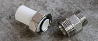
- cable stocking with a tip or a tip for pulling the cable by the central power element and the polymer sheath of the optical cable;
- torsion compensator to prevent axial twisting of the cable being laid;
- intermediate winch with a force limiter for auxiliary cable tightening in transit wells.
6.4 When laying OK in auxiliary polymer pipes, an anti-theft device is also required to prevent the auxiliary tube from moving when preparing it and laying the cable.
6.5 The end of the optical cable is sealed using a cable stocking with a tip or a cable lug for pulling on the central power element and the polymer sheath.
Before work, you need to check the integrity of the twisted lines in the stockings, and also whether there is dirt in the tip.
6.6 The quality of work on laying optical cables in sewers significantly depends on the winch with which the cables are tightened. The following requirements apply to a driven winch:
- it should be possible to smoothly control the speed of cable extension, usually from 0 to 30 m/min;
- the winch must have a dynamometer and a cable tension recorder;
- the winch must be equipped with a cable tension limiter, which automatically turns off the drive when a predetermined traction force is reached.
6.7 Before leaving for the cable laying route, preparatory work is carried out: they check the completeness and functionality of the mechanisms and devices. The end winch must be adjusted to a force less than the maximum permissible tension established for the cable. Adjust the intermediate winches to a force not exceeding 700 N. It is advisable to check and adjust the winches in the presence of a customer representative with a protocol drawn up. Before laying the optical cable, all mechanisms, devices, cable drums, fences, ladders, etc., are transported along the route and installation begins.
In Fig. Figure 2 shows a schematic diagram of laying a cable in a cable duct.
Rice. 2. Schematic diagram of laying an optical cable into a cable duct. 1 — device for winding cable from a drum, 2 — flexible guide pipe, 3 — guide funnels, 4 — cable block, 5 — optical cable, 6 — cable lug with torsion compensator, 7 — billet wire (cable), 8 — hatch bending rollers , 9 - end winch.
6.8 The device for unwinding the cable from the drum is installed at a distance of 1.5–2.0 m from the hatch of the first well, from which cable laying begins. A frame with a corrugated pipe is installed on the well hatch to enter the cable into the sewer channel. The drum with the cable (after removing the casing) is placed on the side of the laying route so that the cable comes out from above. The drum should rotate freely by hand. The end of the cable is freed from the attachment to the drum, as well as from the protective cap.
On the opposite side, hatch-bending rollers are installed on the exit well hatch, and an end winch is installed 2–3 m from the hatch.
Always ensure the stability of the winch and cable reel. An unstable surface needs to be strengthened, for example, installing a winch on a wooden flooring made of boards.
In all transit wells, one anti-theft device and one safety funnel are installed on a polyethylene pipe laid in a channel at the inlet and outlet of the channel. If the installation will be carried out without a polyethylene pipe, then funnels are installed in the channel, the diameter of which corresponds to the diameter of the channel.
In all corner wells, a horizontal spacer and a cable block are installed.
6.9 The end of the cable from which installation begins is cleaned by sealing it in a cable stocking with a cable lug or cable lug. In each case, the cable is pulled by the central strength element and the sheath. The connection of the torsion compensator with the cable (wire) is carried out using ordinary twisting, on which a winding of 3-4 layers of adhesive plastic tape is applied. The twist should not protrude beyond the dimensions of the tip and the torsion compensator.
6.10 The cable is laid using a winch with a tension limiter, rotating it evenly without jerking. The winch pull must not exceed the maximum permissible tensile load specified in the cable specification. On the opposite side, the cable is unwound from the drum manually. Unwinding of the drum by cable tension is unacceptable. If, due to the complex terrain of the route, the traction force of the winch is not enough to pull the cable, then tightening is done in the transit wells.
6.11 During installation, it is necessary to ensure that the cable passes through the corner wells; the cable must pass through the center of the rotary wheel and be fixed with pressure rollers. It is necessary to monitor the operation of intermediate traction winches in transit wells; in the absence of intermediate winches, auxiliary lifting should be done manually with a force of no more than 700 N. It is recommended to prepare workers in advance to perform this work. When pulling the cable by hand, it is forbidden to rest your feet against the walls of the well or its fittings. The cable must not be kinked. It is also necessary to ensure that a loop does not form in front and that the cable goes evenly into the opposite channel. To ensure synchronization of optical cable tightening, service radio communication is required to issue commands.
6.12 On difficult sections of the route and in the presence of large construction lengths of the cable, its laying is carried out in two directions from one of the transit wells, located approximately on a third of the span length. It is desirable that this be a corner well. First, it is advisable to lay a large length in one direction, then unwind the remaining cable on the drum, lay it in a figure eight near the well and then lay it in the other direction. If possible, the cable can be unwound in large loops along the route and then laid. The cable should not be dragged along the ground.
6.13 When a cable appears in the last receiving well, move the end winch to a distance of 20–25 m and continue to pull the cable out of the well along the hatch bending rollers, thereby ensuring a supply of cable for laying out and installation.
6.14 After laying the cable, its end near the tip (stocking) is cut off and sealed with a polyethylene cap.
Laying telephone cable in the ground
Underground installation of telephone cable lines has some advantages over other installation methods. For example, the likelihood of mechanical damage is much lower, less influence of electromagnetic interference, aesthetic component (no cable bundles on buildings, no poles needed, etc.).
When laying a telephone cable in the ground, it is necessary to comply with the requirements of PUE, VSN and SNiPs, which clearly regulate the basic principles of this installation method:
- the minimum depth for laying communication cables is 70 cm. If the cable line crosses a road, residential area, or other spaces with dense buildings or traffic, then the trench is deepened to 115 cm;
- freezing of soil to the specified depths is not allowed;
- to protect against root germination, add earth or sand (10-20 cm) to the bottom of the trench;
- communication cables are laid without bends, fasteners and without “tension”;
- A signal tape is stretched along the entire length of the route or signal poles are installed;
- installation of cable lines is carried out at ambient temperatures down to minus 10-50 C;
- For additional protection, asbestos-cement or PVC pipes can be used.
If special equipment is available, trenchless underground installation of telephone cable is possible.
A little more detail about underground cable routes in this video.
The following brands of telephone cables are often used for installing underground communication lines:
- TB - a cable product armored with steel tapes in a lead sheath with a paper insulator;
- TPPepB - cable insulation is made of PET, shielding is made of aluminum polymer tape (TPpPB - version without screen);
- TPPepBbShp - the cable product is protected by an external hose extruded from PET;
- KSPP, KSPZP - insulator and shell made of PET, tape screen made of aluminum polymer (KSPpZPB - armored version).
Layout of cables
7.1 Optical cables are laid out in the shape of transit wells, starting from the middle of the span in both directions, using the reserve stretched out in the last well (20–25 m), laid them on the console of the corresponding row in the streams closest to the bracket (preferably in the first console place) and secured dressing. The laid out cable should not intersect with other cables running in the same row or obscure the channel openings.
7.2 Since optical cables are not very rigid and can sag when laid on consoles, it is advisable to place them in halves of polyethylene pipes or polyvinyl chloride tubes pre-laid on consoles.
7.3 The cable reserve left in the well for mounting the coupling is rolled up into rings with a diameter of at least 1 m, laid against the wall and attached to the brackets. The cable reserve required for installation of the coupling must be 8 m from the channel at both ends of the cable.
7.4 After laying out the cable, remove all guide funnels and other devices. Then control measurements are made of the attenuation of the optical fiber, which must be within the established kilometer norm. After checking the laid length of the cable, the polyethylene caps at its ends must be restored.
What problems does cable duct solve?
- Protect the laid cable from the negative influence of the atmosphere, earth and hard road surfaces;
- Gives access to replacement, repair or sale of additional branches of telephone or electrical lines, without resorting to opening the soil or damaging the road surface.
What types of sewer systems are divided into?
- For installation of pipes, special trenches can be pre-prepared. To do this, a certain layer of soil is removed.
- Using the trenchless drilling method allows you to lay underground pipes without removing the top layers of soil.
In addition, such sewerage systems are distinguished by such parameters as cross-sectional size and the shape of the wells and pipes themselves. And, of course, the classification takes into account the material used to manufacture the elements of such a sewer system.
Concrete, plastic or brickwork can be used for wells. Pipes can be made from: asbestos, concrete, plastic, fiberglass, steel or hemp. The most commonly used materials are asbestos and plastic. In some cases, pipes are replaced with plastic blocks assembled from several sections. Such blocks are called multichannels.
Cable cutting
8.1 Cable cutting must be carried out by trained and certified personnel. It is necessary to use only a special set of tools for installing optical cables.
8.2 The length of the groove is indicated in the special instructions for installing couplings. To carry out incoming inspection, the length of the cutting section is no more than 300 mm.
8.3 The cutting of DPL brand cable must be carried out in the manner described below.
8.3.1 Using a roller knife (or stripper), perform a transverse opening of the outer sheath of the cable along with the tape armor.
8.3.2 From the point of transverse opening to the end of the cable, using a plow knife, make a longitudinal cut of the sheath and armor (preferably two oppositely located).
8.3.3 Using pliers, remove the outer sheath of the cable along with the armor.
8.3.4 To carry out grounding, make a transverse and longitudinal cut of the shell at the required length, spray it with a flame or a stream of hot air so that the shell comes unstuck from the armor, and remove the shell from the armor with pliers.
8.3.5 Using a roller knife, perform a transverse opening of the inner cable sheath.
8.3.6 From the point of transverse opening to the end of the cable, use a plow knife to make a longitudinal cut of the inner sheath (preferably two oppositely located).
8.3.7 Use pliers to remove the inner sheath of the cable.
8.3.8 Remove the winding thread from the section of the cable free of sheaths.
8.3.9 Using gasoline or special liquid D-Gel, remove the intermodular hydrophobic filler.
8.3.10 Unwind the optical modules.
8.3.11 Remove the central power element, leaving the length necessary for installing the cable into the coupling.
8.3.12 Opening optical modules in order to remove optical fibers should only be done using a precision tool that prevents damage to the optical fibers, for example, a special stripper. Make a cut on each optical module.
8.3.13 Carefully pull off the module shell.
8.3.14 Remove the hydrophobic filler with a special liquid D-Gel.
8.3.15 Wipe the fibers with isopropyl alcohol.
Installation of inspection wells
Such inspection wells are installed in main sewers in the same way as in conventional sewers.
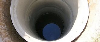
They look like containers that have a hard bottom and are closed with a hatch on top. In this case, a neck is also installed between the well itself and the hatch. The internal walls have special holes where pipes with cables are inserted. The majority of tanks of this type are equipped with two hatches at once. And, if the outer hatch can be removed by anyone, then to open the inner hatch you will need a special secret key.
In total, depending on the location of the cable, the wells differ in:
- checkpoints;
- station;
- dividing.
If we talk about walkways, they are most often used on straight sections or on those that have a horizontal deviation of no more than 30°. The second option is mounted where the network bends. And dividing, based on the name, are installed at those points where separation into several channels occurs.
During the construction of cable ducts, inspection wells of various sizes are installed in different places.
This is important: the wells inside must have enough space to be able to manipulate the cables.
The materials themselves used for the manufacture of such elements also depend on their depth. For example, in case of installation close to the surface, it is recommended to use plastic products, and in case of recess - reinforced concrete.
Installation of couplings
9.1 Installation is carried out using optical couplings produced by Svyazstroydetal.
9.2 Installation is carried out in accordance with the instructions for installing optical couplings. Upon completion of installation, measure the attenuation in each fiber of the installed cable. When laying in a cable duct, the mounted coupling, together with the technological supply of the optical cable, is installed on a bracket on the wall of the cable duct.
9.3 During installation of couplings, it is necessary to avoid contact of optical fibers with an unprotected body in order to prevent injury from glass particles of optical fibers.
Description of cable duct
Cable duct installation
Cable ducting is a system of channels located underground and containers that contain telephone and sometimes electrical cables. The cable duct consists of the following elements:
- pipes designed to protect wires;
- wells installed to check the integrity of cables and carry out work to replace, insulate or increase their work potential.
But cables can be laid without the use of special pipelines; for this, already laid trenches, free basements or collectors are used. Fasteners are used to secure such lines.
Laying cables in sewers in practice
Fiber optic cable outside buildings within populated areas is laid in most cases in telephone sewers. It is based on round pipes with an internal diameter of 100 mm made of asbestos cement, concrete or plastic. Telephone sewerage is laid at a depth of 0.4 to 1.5 m from separate blocks hermetically joined together. After 40-100 m, inspection wells are placed on the route, on the walls of which consoles for cable laying are mounted. The difference between the technology for laying electrical and optical cables in telephone ducts is that the pulling force of the latter should not exceed the permissible value, and cable torsion is not allowed.
Cable laying in a telephone sewer is usually carried out in a free channel, where during construction a wire is left for pulling. In its absence, the passage of channels is carried out using a channel preparation device, which is an elastic fiberglass rod with a diameter of 10 mm and a length of up to 150 m, wound on a drum with a diameter of about 1 m. The rod is pushed into the channel to the adjacent well. Next, attach the end of the cable to the tip of the rod and pull it back. For fastening, you need to use a special tip, which is fixed on the cable by its strength element and armor covers and must be equipped with a torsion compensator. Pulling should be done smoothly and without jerking.
If there are sharp turns on the route, a rotary roller is installed in the well. In its absence, the cable is pulled out of this well in a loop, and further installation is carried out as from the starting point of the route. Often, to save construction time, the cable is sorted by hand directly in the well, directed into the sewer pipe.
Requirements for laying pipelines in cable ducts
For pipelines laid in cable ducts, a number of requirements must be observed. Firstly, the inner surface of the pipeline must be smooth, and the pipeline itself must be durable, frost-resistant, waterproof and resistant to groundwater.
For distribution and trunk networks, in areas where small-channel blocks are used, it is required to use polyethylene pipes with an internal diameter of 55-58 mm. In other cases, pipelines should be made of concrete and asbestos-cement pipes with an internal diameter of 90-100 mm and 100 mm, respectively, as well as using recycled polyethylene pipes with an outer diameter of 63 mm and 110 mm. The pipeline must not have a harmful effect on the cable sheath.