Why is chamfering necessary?
Processing the ends of sheets or pipe walls is needed for:
- Good penetration and reliable connection of welding seams
- Reducing welding time
- Preventing injury to employees from sharp corners of the product
- Simplifying the upcoming installation of the metal structure being erected
- To avoid manual sanding of sheet or pipe edges
If chamfering is not performed, then in products whose thickness exceeds 5 mm, the welding seam may come apart over time and the structure will lose strength.
Brief instructions for installing laminate flooring yourself
If you are installing laminate flooring yourself, and you have no experience in this work, then choose direct installation. When performing work, follow the following rules:
Start laying the laminate from the farthest and brightest corner of the room.
There should be a gap of 1 cm between the edge of the laminate and the wall. For its construction, it is most convenient to use pieces of plywood 10 mm thick. They are inserted during installation and removed upon completion of work.
To improve sealing, the lock ridge can be lubricated with latex sealant.
Detailed instructions: How to lay laminate flooring with your own hands.
Panel trims can only be used if their length is more than 30 cm.
The final row of planks almost always requires adjustment. Saw off the plank on the side that will be adjacent to the wall. Subsequently, this place will be covered with a plinth. It will also hide the technological gap.
Useful article? Add to your bookmarks!
We advise you to study - Which heating radiators are best to choose for an apartment with a central heating system
Chamfer angle
Chamfer angle
from the edge of a sheet or pipe is selected based on the design features of the product or the assigned welding task. As a rule, the standard chamfer angle for metal sheet profiles is 45°, for pipes – 37.5°.
There are three ways to cut an edge from rolled metal:
- Y-shaped way;
- X-shaped;
- J-shaped (another name is “glass” chamfer);
- Also, in the technical literature you can find another letter designation:
V, K and U-shaped chamfer .
Features of different types of chamfers
- The most common methods of edge removal in production are the Y-shaped method and the X-shaped one.
- For a high-precision weld (for example, on products of complex design), a chamfer with a curved surface is used.
- J-shaped chamfer is performed using special automatic chamfers. This method creates a larger weld pool than other methods.
Other types of edge cutting
(butt type of connection with a broken edge) is not used so often in production.
Chamfer as a structural element of a part
Often during the manufacturing process of parts it becomes necessary to carry out additional processing of the internal and external edges. It is carried out at a given angle. The surface resulting from this processing is called a chamfer.
Chamfering is used to solve the following problems:
- technological (ensuring the best connection of two parts);
- technical (giving the product the required shape);
- ergonomic (ensuring the most convenient and safe use of the product);
- improving the decorative and aesthetic properties of the finished product.
This treatment is used in many areas: mechanical engineering, in preparation for welding work, in the manufacture of furniture and interior decorative products. The choice of methods depends on the tasks assigned and always corresponds to the design documentation.
Why chamfering is necessary
Finishing the ends of parts, the edges of holes, the outside of bushings, and bolts is necessary to solve problems determined individually in certain types of processing.
In the manufacture of metal products:
- runaway undercuts are eliminated using a chamfer;
- reduction of time for installation of the structure;
- increasing the reliability of fastening elements (explains the need to chamfer the bolted connection);
- reduces the risk of injury during assembly work;
- the speed and accuracy of assembling individual structural elements of components and mechanisms increases.
Before carrying out welding work:
- obtaining a reliable welded joint (better heating of the seams and adhesion of the solder occurs);
- compliance with safety regulations and reduction of injuries;
- The time required to carry out the welding operation is reduced.
Chamfering in furniture production allows you to:
- eliminate the consequences of cutting elements of furniture products during woodworking;
- give the necessary aesthetic appearance to each element of furniture (wooden product);
- prepare the surface and edges of the part for decorative processing;
- create holes for secret fastening of individual furniture elements with the subsequent use of decorative plugs and inserts.
To select the necessary parameters, a special table has been developed that allows for the necessary processing.
Chamfer angle
This parameter is determined by the design features of the manufactured part, assembly or assembly as a whole. The chamfer angle is determined by accepted standards and specifications. The value of this indicator depends on the selected material and the purpose of the specific structural element. For metal products, the state standard establishes the following values:
- metal sheets - 45°;
- pipes and cylindrical products 37.5°.
In accordance with the requirements of GOST, the possible value of the chamfer leg size is determined. The value of this parameter varies from 0.1 mm to 250 mm depending on the shape and size of the part.
For structures made of wood or synthetic materials, the angle values are determined by the requirements for a particular product. They are specified in the design documentation, where the minimum and maximum angle values and leg size are set.
Types of chamfers
This type of processing refers to the resulting surface shape. It is cut in several ways. These methods are designated by the Latin letters “Y”, “X” and “J”. In some literature and reference books on metalworking you can find other designations “V”, “K”, and “U”. These designations indicate the method for obtaining the required cut.
The most common are the first two methods. These types of chamfers are produced using standard metal-cutting tools on various processing machines: turning, milling, combined, CNC machines.
They also obtain chamfers for threads according to GOST. Currently, developed methods and equipment make it possible to obtain standard chamfer sizes.
In most cases, the procedure and rules for obtaining chamfers, geometric dimensions, and rules for drawing on drawings are determined by the established GOST 10549-80.
It sets valid values for the following parameters:
- thread run parameters;
- permissible undercut dimensions;
- the size of the permitted grooves at the outlet of the thread cutting tool used;
- chamfer sizes depending on the diameter and type of thread applied (metric or inch, pipe, conical, trapezoidal);
- For external threads, the run-off and undercut dimensions are established.
To obtain a more complex type of chamfer “J”, special chamfer removers are used. This type is most often used during preparatory work before welding. Thanks to this shape, a larger volume weld pool is obtained, which helps to obtain a stronger and higher-quality seam.
In some cases, other individual edge cutting forms are used. In this case, the procedure for their implementation is given in other standards or technical specifications. For example, Standard No. 5264 of 1980 provides rules for making a joint with a broken bevel.
Manufacturing methods
The methods used to make edges depend on the following conditions:
- purpose of the chamfer being prepared;
- the material from which the structural element is made;
- the equipment used.
According to the method used, the following types of edge preparation are distinguished:
- mechanical cutting;
- oxygen gas;
- air-plasma.
To cut bevels on metal products, various metalworking equipment equipped with special tools is used. With its help you can obtain the required chamfer size for the thread. The use of special cutters and milling tools allows chamfering of holes.
Particular attention is paid to preparing the edges of the transition from one shaft diameter to another. This transition is called a fillet. It is quite common in mechanical engineering. The design of fillets with shafts is carried out in various ways in compliance with established standards.
As already noted, special chamfer removers are used for more accurate edge removal. They allow you to obtain a given angle and leg length.
Designation on drawings
A graphic representation of the future structure, component or assembly is depicted on the drawings in accordance with the Unified System of Design Documentation. It determines the order and rules for applying graphic images, symbols and designations for each element. It is a competent drawing that allows the manufacturer to understand how and with what tool the processing should be carried out.
For chamfers in the drawing they indicate:
- bevel width;
- bevel angle value (its value is measured relative to the main axis of the part or the entire unit)
The designation of these parameters is made in the metric system of measurements. All linear dimensions are indicated in millimeters, and angular values in degrees. In accordance with the requirements of the ESKD, dimensions are applied in certain places, indicating which element of the part or mechanism it relates to.
If there is not enough space inside the part to indicate the parameters of the internal chamfer, the values are placed outside the product, with a mark indicating which surface the dimension relates to. This mark is made with an arrow directed towards the required side of the part.
On the shelf, which is graphically connected to the arrow, the value of the angle of the chamfer being removed is indicated (for example, 45°).
When displaying a symmetrical sample (at the same angle or the same leg), it is allowed to specify one value. Often, drawings indicate two linear dimensions that characterize the parameters of the chamfer being removed.
If you find an error, please select a piece of text and press Ctrl+Enter.
Features of the chamfering process
To cut edges on a metal product, special units are used - bevelers.
, differing in cutting method into three types (air-flame, mechanical and oxygen-gas equipment).
The edge cutting process is as follows:
- Using clamps, the chamfer is attached to the edge of a sheet or the inside of a metal pipe.
- Next, the required sharpening angle is set.
- When the machine is turned on, the cutting head is brought to the workpiece and the chamfer cutting process occurs.
- After finishing the work, the cutter returns to its original position.
- After chamfer cutting, the working surface of the product is considered prepared for further welding work.
When cutting a chamfer, a welding container (bath) is formed, where the hot welding composition is collected. A chamfered edge has a certain dullness of about 3-5 mm. When the container is filled with welding compound, the blunted area melts itself. Thanks to this, the required seam tightness is achieved and additional reliability is created.
Which laminate is better, with or without chamfer?
The description of the type of chamfers, their strengths and weaknesses does not answer a simple question: which laminate is better, with or without a chamfer? Let's try to compare the main selection criteria:
- price. The advantage is natural for a laminate without a chamfer. After all, to form a bevel, additional technological operations are required. If we compare specific figures, the laminate of the middle price segment is 50-150 rubles/m2 more expensive, premium class – by 500-600 rubles/m2;
- moisture resistance is definitely higher for lamellas with beveled edges - interlocking joints and cuts are necessarily treated with protective compounds. For laminate without chamfer, such treatment is carried out only for moisture-resistant flooring;
- design, without discussion, is better for planks with beveled corners;
- the service life is approximately the same, but there is a nuance: by the end of its service life, a laminate without a chamfer has a shabby appearance, while a laminate with a chamfer retains its original appearance;
- role in the interior. Laminate without chamfer performs passive functions when developing the design of each room - it is selected to match the furniture, walls and design style. With a chamfer - it dictates the style direction. At the same time, using a variety of layouts, it can visually change the size of the room.
As we can see from a brief analysis, only the price is attractive in a laminate without a chamfer. Otherwise, it is inferior in all respects to panels with a chamfer.
Edge cutting methods
Currently, two methods of edge removal are used in production: thermal and mechanical.
.
Mechanical chamfer
is considered the highest quality, since this method is performed on special equipment - beveling machines (edge cutters), milling machines, edge splitters and other devices. The advantages of this method are as follows:
- After chamfering, the product retains its structure and does not lose its physical and chemical properties.
- The mechanical method ensures high tightness and reliability of future welds
- Save time.
Thermal method
– air-plasma chamfer and gas-flame chamfer. Air-plasma cutting of edges allows you to obtain a chamfer appearance close to the factory (or mechanical chamfer). However, it requires a perfectly smooth surface of the sheet or pipes at a certain angle. In many industries, this type of chamfering is the main one due to its efficiency and high speed of processing products. It is performed using special plasma cutting equipment.
Gas-plasma chamfering
does not require special conditions for implementation and is characterized by low cost. But the quality of the cut is lower than with the mechanical or air-flame method. Often such chamfer cutting requires additional machining. This method is used for artisanal processing of used pipes. When using the thermal method of chamfer cutting (gas-plasma and air-plasma chamfer cutting), due to overheating, a section appears in the metal product with altered physical and chemical properties (thermal influence zone). This negatively affects the tightness and reliability of future welds and the strength of the structure itself.
Mechanical chamfering preserves the properties of the product and does not affect the quality of future welding work. Mechanical chamfering method
is a kind of guarantor of the quality of processing of metal products before welding. The only “disadvantage” of this method is the high cost of the units and the complexity of the work.
You can find out the cost of mechanical bevel removers by calling ☎
Hello to all DIYers!
When planing wooden blocks and narrow boards, it is almost always necessary to remove small chamfers from the ribs in order to blunt them to one degree or another. However, to do this you have to hold the plane obliquely, at about a 45-degree angle, which is not always convenient, especially when working with electric planes.
You can get out of this situation if you make a special device in the form of a long longitudinal angle into which the processed block would be placed and thus the edge from which you need to chamfer would be on top.
In addition, such a device could also be used for planing faceted and round wooden blanks (for example, handles for garden tools: shovels, forks, rakes, etc.), which are very inconvenient to plan on a flat surface.
I thought about making such a device just when I was planing blanks for shovel handles (see my article “”), since with such a device my work would have gone much easier and faster.
As a result, I decided to make this device, for which I needed the following accessories:
Materials and fasteners:
Two wooden planks 2 cm thick, 4 cm wide, and 6 cm, and 2 m long. Wooden plank 2 cm thick, 5 cm wide, and 50 cm long. Wood screws 4x50 mm.
Tools:
Drawing and measuring tools (pencil, tape measure and square). Awl. A jigsaw with a file for curved cutting. Electric drill-screwdriver. Metal drill with a diameter of 4 mm. Spherical cutter for wood. Screwdriver bit RN2, for driving screws. Sandpaper.
Urban planning[edit]
Many city blocks in Barcelona, Valencia and various other cities in Spain and street corners (curbs) in Ponce, Puerto Rico are sloped. The chamfer was conceived as a beautification and modernization of urban space in the mid-19th century Eixample district of Barcelona, or Expansion District, where buildings follow the bevel of sidewalks and streets. This innovative design opens up wider vistas, provides pleasant pedestrian areas and ensures better visibility when cornering. Additionally, one could consider making the turn somewhat more comfortable by presumably drivers not having to slow down as much when making the turn as they would if the angle were a 90 degree square,[ edit
], although In Barcelona, most sloping corners are used as parking spaces or loading/unloading areas, leaving traffic flowing like regular 90-degree street corners.
- Sloped sidewalk street corner in historic Ponce, Puerto Rico
- The Great Gate (Darwaza-i Rauza) is the gate to the Taj Mahal, with the beveled corners of the tower.
- A sloping building and street corner in Barcelona's Passeig de Gràcia. Here the building is sloped, but the sidewalk/street has taken on a conventional 90-degree layout, eliminating a loading area or parking spaces.
- The original design of the Barcelona quarter, Eixample, with chamfered building and street corners and gardens that never came into being.
Operating procedure
First, we mark a 6 cm wide plank and drill along its entire length, with 5 or 6 holes for screws on one side.
On the opposite side of the plank, we countersink these holes for the screw heads using a spherical wood cutter.
Then we insert screws into these holes and screw our plank to the end of another 4 cm wide plank.
As a result, we get this wooden corner 2 m long.
After that, using a jigsaw, we cut out such a blank from a short strip.
It will serve as a stopper for planed workpieces, and at the same time, as a support for our device. We also mark this blank and drill three holes in it for screws.
And then, using screws, we screw this workpiece to the end of our corner device.
From the remaining piece of the plank we cut out two more blanks like this with a jigsaw.
We will screw them to the back of our device, where they will serve as additional supports.
At the very back of the device, we drill two holes for screws on each side.
We also countersink the upper parts of these holes with a spherical wood cutter in order to recess the screw heads.
Now we screw our blanks with screws.
All elements of the device, and especially the ends, are treated with sandpaper.
And now our device is ready! This is what the back looks like.
And so the front part.
Now it will be possible to process bars using this device. For example, I put a blank block for a shovel handle into this device - rear view.
And this is the front view.
But the block is not square, but rectangular in cross-section. Now it will be quite easy to chamfer from such bars.
But I put a purchased handle for a shovel, round in cross-section, into the device.
Such round workpieces will now also be very convenient to process in this device. Moreover, it will be possible not only to plan them, but also to carry out other types of processing, for example, drilling holes in them or sawing them.
Well, that’s probably all! Goodbye to everyone and have easy-to-use devices!
Usually, when planing wooden blocks or narrow boards, it is often necessary to remove small chamfers from the edges of the workpiece in order to reduce the sharpness of the corners and also make them more beautiful. To do this under normal conditions, you have to hold the workpiece with the plane at angles of about 45 degrees, which is not particularly convenient, especially when you are working with an electric plane, which is many times heavier than a manual one. This problem can be solved using your own special device, which will look like a longitudinal corner, where the block will be placed, which will be processed in the future, and its edge will be located at the top, which is convenient for processing.
This arrangement of the workpiece in a homemade device will also help for planing faceted and round bars, as well as wooden handles, which are inconvenient to process on a flat surface. The author of the homemade product thought about making such a device, since the need for it arose when he was planing blanks for shovel handles, because with such a device the work was completed faster, and it was also much more convenient to work this way.
In order to make this device, you need:
Two wooden planks 2 cm thick, 4 cm wide, and 6 cm, and 2 m long. Wooden plank 2 cm thick, 5 cm wide, and 50 cm long. Wood screws 4x50 mm. Drawing and measuring tools (pencil, tape measure and square). Awl. A jigsaw with a file for curved cutting. Electric drill-screwdriver. Metal drill with a diameter of 4 mm. Spherical cutter for wood. Cross (curly) bit RN2, for driving screws. Sandpaper.
When all the materials and tools are available, then you can begin the most interesting part, this assembly process.
Step one.
The first step is to decide on the dimensions; you can use the dimensions given here, but if your workpiece is large, then simply increase the size of all the components to the required size.
Using a pencil, we mark a plank 6 cm wide, then using a screwdriver and a drill, we drill holes along its entire length, on one side there are 5 or 6 holes for screws, as a rule, the more, the better, and more reliable. Step two.
Having positioned the plank on the opposite side, using a countersink installed in a screwdriver chuck, we increase the dimensions for the screw heads, using a spherical wood cutter.
After we have enlarged the holes for the caps, we insert screws into these holes and screw our plank to the end of another 4 cm wide plank. What should happen at this stage can be seen in the photo, this is the so-called wooden corner, its length is 2 m, made for so that there is a reserve in length used in processing workpieces, thereby increasing the range of application, since you do not have to combine the sizes of either small or large devices, and it is easier and more practical to make one, but longer. Step three.
Using a jigsaw, we cut out a smaller piece from a board, which will be the supporting part, with which the device will be held on a flat surface, this process requires sufficient precision and accuracy; for better accuracy, use a special corner stand on the jigsaw, which will help in creating even cuts.
When working with a jigsaw, be extremely careful and do not forget to wear safety glasses and gloves, protecting yourself from accidental contact with sawdust and wood dust, as well as protecting yourself from the tool slipping out of your hands. Step four.
The previous workpiece, whose role is to hold our corner part, must be drawn, the lines should correspond to an angle of 45 degrees, as on the main part, for a better match, attach the future support and outline it with a pencil.
To secure it, you need to drill holes for the screws, in this case there will be three of them, which is quite enough, we select the drill according to the diameter of the screws so that the thread passes without difficulty. Step five.
Then we tighten the screws with a screwdriver, that is, we screw this workpiece to the end of our corner device, try not to overdo it with the tightening force, so as not to damage the support and form a crack in it.
The remaining part of the strip will also be useful; we make the same blanks from it using a jigsaw; you will need two of these. We supplement the corner with two more supports, which will make it much more stable, and it will also acquire a larger workload, which is also important when processing. We screw them in the same way as the first support. Step six.
The back of the device must be drilled on each side; we use a screwdriver with a drill whose diameter is equal to the thickness of the screw; for strength, we make two holes on each side to prevent rotation.
The location of the holes, as in the previous stages, must be processed with a spherical wood cutter in order to recess the screw heads and thereby eliminate accidental snagging. Step seven.
Armed with a screwdriver and a bat attachment for driving screws, we tighten the screws into the workpieces. Next, we move on to more precise processing, for this we will use sandpaper, as usual, we start with coarser paper, gradually reducing the grain size as we approach the finish of sanding. With this our homemade device is ready, now let’s look at it from all sides for a full assessment. This is what the back looks like. And so the front part. After you make such a device, you will be able to process bars without any difficulties or inconveniences, be it a wooden handle or a workpiece with square edges.
A chamfer is the surface of a product that is formed during the processing of rolled products or pipes by bevelling the end edge of the material. The chamfer is necessary to prepare the edges of sheets, beams and pipes for welding.
The main types of chamfer are:
- "Gas"
. This is the cheapest type of pipe bevel due to its low quality. However, this type is one of the most common. This chamfer is removed using. The “Gas” chamfer can also be made in the field. Its surface usually has characteristic grooves, which are formed from a gas stream (propane or acetylene). - "Plasma"
. Externally, this type of chamfer is practically no different from “mechanics”. It can also be classified as an air plasma cutter, a compressor, and a compressor that forces the cutter to move strictly in a circle when setting a specific bevel angle. - "Mechanics"
. This is a factory chamfer, of the best quality. For chamfering “mechanics” and are used. In the pipe market, this bevel is mainly used due to the high quality of the bevel.
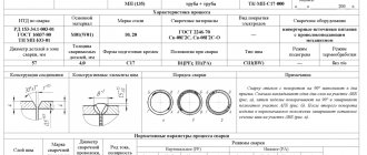
What is the purpose of chamfering? When welding workpieces, metal penetration occurs, which subsequently ensures that the edges are connected to each other. If the metal thickness is more than 3-5 mm, obtaining a complete and high-quality connection becomes difficult. To obtain high-quality penetration, this type of processing is carried out: it allows you to create a so-called weld pool, which is filled with a welding compound during the welding process. It is important to remember that the edge prepared for welding is an edge with a chamfer and bluntness (see the figure and its symbols below).
Types of chamfers (methods of cutting edges).
There are three main methods for preparing edges for welding: Y-shape, X-shape, and J-shape. Sometimes in some sources they are designated by the letters: V, K and U, respectively. Here and below, the above methods will be designated by the letters: Y, XJ Most often, Y-shaped cutting of edges is carried out, but there is also an X-shaped method. In special cases, when there is an increased requirement for the quality of the weld, a J-shaped chamfer is used, that is, a chamfer with a curved surface (not to be confused with a curved edge!).
In addition to the main methods of processing Y, X. J edges, there are a number of edge preparations. They are not so rare, and their description cannot be found everywhere. For example, GOST 5264-80 describes the butt type of connection with a broken edge braid; symbol – C14.
The diagrams above show several examples of processing methods:
1: example of Y-shaped chamfering method;
2, 3, 4: examples of the X-shaped chamfering method;
5: Y-shaped processing of the ends of two pipes with their subsequent connection;
Methods for chamfering.
There are two ways to remove a chamfer: mechanical and thermal (Table 1). Mechanical chamfering is carried out using milling, edge splitting and edge planing machines. For thermal chamfering, gas cutting machines (stationary or portable) are used, which perform plasma or oxy-fuel cutting. However, the more preferable method is mechanical, since it eliminates changes in the physical and chemical properties of the material as a result of overheating. As is known, during heat treatment a so-called thermal influence zone is formed. The thermally affected zone is the carburization of the edge due to overheating of the material, which impairs weldability and increases the fragility and brittleness of the edge. But, despite these disadvantages, the thermal method is quite common due to its simplicity and speed of application, and the relatively low cost of equipment.
Table 1
. Advantages and disadvantages of thermal and mechanical chamfering methods.
Table 1 states that thermal chamfering can be done quickly and cheaply. Of the processing methods described above, mechanical is still preferable, since it allows you to protect the metal from overheating and from subsequent changes in physical and chemical properties. In the West, by the way, this method is called cold-cutting, that is, a type of processing in which there is no thermal effect on the metal, and therefore there are no changes in the chemical and physical properties of the metal.
Video material:
1.
Pipe cutting with a gas cutting machine CG2-11G, simultaneous chamfering of the pipe is carried out by tilting the cutter at the required angle.
2.
Chamfering a 76x6mm pipe using the Mongoose-2MT machine
3.
Chamfering a pipe using a TT series chamfer, as well as cutting a pipe with chamfering using a split pipe cutter P3-SD
The group offers for supply equipment for chamfering pipes and metal using all of the above processing methods (gas, plasma, mechanical).
For technological, ergonomic, and more often for aesthetic purposes, a chamfer is used to process the edges of products. Any person has heard this short word more than once in his life, often without knowing its meaning. So, chamfer - what is it and where can it be found? How important is this detail?
Chamfer designation in the drawing
The dimensions of the chamfers in the drawing, at an angle of 45°, are marked with dimension lines or on the shelf of a leader line; if its size on the scale of the drawing is 1 mm or less, the chamfer is displayed as shown in the image below on the right side.
Designation of a chamfer on the drawing at an angle of 45°
Chamfers with an angle not equal to 45° are indicated by linear and angular dimensions or two linear dimensions.
Designation of a chamfer with an angle not equal to forty-five degrees
A chamfer is nothing more than an element of a part. The word chamfer owes its origin to the French word “ faccete ,” which means beveled parts of corners, edges, etc. The main part of chamfers is intended to blunt sharp corners in order to ensure the safety of subsequent technological operations or operation of products and mechanisms.
On technical drawings, chamfers and their geometric parameters are indicated in cases where it is necessary to clearly indicate its presence due to a technical solution. In other cases, chamfers or other edge shapes are not specified, but must be blunted .
Mainly, as mentioned above, chamfers are intended to ensure safety during further interaction between a person and the products of his production activities, but in some cases they are needed as decorative elements introduced by designers into the composition of the product.
Bevels are very often used in the woodworking industry. The presence of chamfers here, combined with roundings that turn into fillets and back, combine very well with flat surfaces and give the product a finished appearance. Even the presence of a simple chamfer on any part visually gives it volume, not to mention shaped chamfers with changing cutting trajectories and inclination angles.
When finishing mirrors, decorative chamfers are made along the edges, in the form of small bevels of the edges. These kinds of edges are obtained as a result of grinding with a special diamond tool, on machines designed for carrying out such types of work, with abundant cooling. Edges processed in this way are called “ beveled ”. When making doors, or any other parts of the interior, glazing elements are used in the form of small tiles of a given size with a bevel. In combination with noble wood, they create a composition that gives a special solemn look and an atmosphere of comfort.
There are chamfers with a fairly gentle bevel, which allow the parts to perform functions that ensure guaranteed engagement or engagement with the mating components of assemblies and mechanisms.
In internal combustion engines, gas timing is an important determining part of the operation of the system as a whole. To realize the conditions of gas exchange, the inlet and outlet openings must open and close strictly in a certain order and ensure effective gas exchange. The timely supply of the combustible mixture and the release of exhaust gases is carried out by valves, which are driven by the kinematic elements of the mechanisms. One of the components of the valve is the sealing chamfer; it is entrusted with the important function of guaranteed shutoff and ensuring the unhindered release of gases.
For high-quality metal welding, when connecting steel sheets exceeding the cross-sectional size of six or eight millimeters, technological chamfers are usually removed. There are two ways to prepare edges for welding - heat treatment or mechanical. Recently, edge preparation is most often used by the chipping method, in which the metal is displaced under the influence of tangential stresses. Such operations are performed by special machines with a system of guide rollers and a gripping round tool driven through a gearbox from an electric motor. The use of such mechanisms can significantly speed up preparatory work. The edge processing machine, "SNR - 12" from Spain, is an effective tool of this type.
Chamfer - what is it?
First of all, this is the bevel of the edge of the corner of the material. It is used for technological purposes in mechanical engineering and metalworking to improve the quality of the weld. In the same area you can find a chamfer on the mounting hole, which serves to reduce the likelihood of injury from sharp edges. The same method of preparing holes can be seen in the production of furniture, only in this case it is used for fastening parts flush (when the heads of bolts and screws are not visible).
For aesthetic purposes, chamfering is also used when laying floors. Thanks to this method of edge processing, cracks that form due to changes in temperature and humidity are not noticeable.
Popular manufacturers of chamfered laminate
Many manufacturers supply high-quality laminate to the construction markets of the CIS countries. Among them are:
"Quick Step". The Belgian company is known for its own development of the Uniclick locking connection and a wide range of quality products for any consumer needs;
"Balterio". The chamfer and texture of the lamella, thanks to unique technology, most realistically imitate natural wood.
Tarkett. An international company (headquartered in France) has its production facilities in many countries. There are production facilities in Russia. The laminate produced here has a large assortment, two types of locks (T-lock and 2-lock) and a long warranty period - up to 25 years.
Products of this brand are also available from China. Characterized by an affordable price and not always high-quality chamfers (different milling depths);
"Pergo" The Swedish company has been working in the flooring market for a long time. The highlight of the product is its unique antiseptic coating. Therefore, it is used mainly in places where sterile cleanliness is required: healthcare, children's rooms in apartments and houses;
"Egger" The German company has patented the LocTec latch and a unique resin impregnation, which makes it possible to maintain the moisture-proof properties of the edge bevels throughout the entire period of operation. Famous for the white and light raw color of the laminate, which predominates in the model range;
"Kronostar". According to reviews from consumers and specialists, the company's products have the best price/quality ratio, and therefore demand in Russia is constantly growing;
"Kronotex". German quality with a long warranty period (30 years) speaks for itself;
Kronospan. The company produces premium products. Therefore, not everyone can afford it. The high cost is justified by the corresponding quality characteristics;
"Classen". The product has been developed for the harshest operating conditions. Therefore, it easily withstands the effects of adverse factors present in the installation areas;
"Kronoflooring". The company's products have a stylish design that allows you to choose a texture for many types of flooring: parquet, solid boards, tiles, porcelain stoneware. The slats have increased strength, the melamine film has antibacterial additives.
As you can see from the list above, you can choose a laminate to suit every taste and pocket.
Wooden floors
When laying floors with wooden boards, you need to take into account many nuances. This includes the quality of the material, the degree of drying, and the conditions under which the surface will be used. While the first two questions can be easily determined in advance, the operating conditions of the floor cannot always be reliably predicted. In this case, a chamfer is used. What this is is explained above. It will not only make the floor look neater and more beautiful, but will also help to avoid visible gaps between the boards, which are sure to appear over time.
When working with solid wood, the question may arise: “How to make a chamfer?” Moreover, a woodworking machine is not entirely suitable for this. First of all, the material is sanded clean (this will be impossible to do later). For chamfering, use an edge cutter on a bearing. This allows you to achieve ideal quality of the processed surface even with slight curvature of the boards.
Welds
Experienced professionals will tell you that when making welds, a chamfer is necessary. That this will not only ensure high quality connections, but will also greatly facilitate their work.
When joining two sheets of steel, a chamfer is used to circumvent the limitation on the depth of weld penetration of the seam. Structurally, this element can be made in two ways: with a straight and curved surface. In this case, the second method is more often used, since such a depression has a larger volume.
Laminate
Today, not everyone can afford floors made of solid wood and parquet boards due to the high labor costs and loss of time for repair work. You can increasingly find laminate floors on apartment floors. It is not only easy and quick to lay, but also has excellent performance and aesthetic qualities, in many ways not inferior to natural surfaces.
Currently, laminate flooring with a chamfer on the edge is more often purchased on the market. What is this and how does it affect the final result? First of all, it looks more representative, completely replicating the appearance of natural wood. Secondly, this minor nuance masks changes in the gaps between the boards that appear during the use of the floor.
Many consumers are still skeptical about such flooring. This is argued by the fact that a chamfer in a laminate is unacceptable, as this will allow dust and dirt to accumulate in the recesses and penetrate into the seams. This is not true, because modern material production technologies make it possible to make laminate flooring water- and dirt-proof over its entire surface. A high-quality lock will prevent debris from penetrating into the seams.
Pros and cons of chamfering
Slats with a beveled front edge have additional advantages compared to laminate without a chamfer . Among them:
- more respectable appearance - beautiful design and resemblance to expensive parquet;
- the ability to visually change the dimensions of the room using various schemes for laying laminate with a chamfer;
- the ability to harmoniously fit into any interior of an apartment or house. Especially in such as neoclassicism, loft, Provence, country;
- better protection of locking joints from direct contact with water, but only in the first years of operation. In the future, work is needed to restore the protective layer;
A laminate with a chamfer will withstand such a puddle for ten minutes without consequences.
Consequences of short-term contact with water of laminate without chamfer.
- reducing the load on the edge edge during horizontal vibration, as a result of which it retains its original appearance for a long time;
The shabby look of regular laminate flooring.
- absence of protruding corners (they are cut off) when individual planks are deformed (a common occurrence for flooring made from laminated panels), and, consequently, damaged slats.
Damaged corners of the slats.
- the ability to visually hide slightly loose joints due to a weakened lock.
There are also disadvantages. What would it be like without them, dear ones:
- thinning of the protective layer of the chamfer, which requires regular floor care;
- more difficult cleaning - debris from the recesses does not want to be removed with a simple broom. Need a vacuum cleaner;
- chamfer is contraindicated for rooms such as a bathroom, kitchen, toilet. Especially the kitchen, where splashes of fat caught in the recess will cause many unpleasant moments for the hostess.
How to choose a laminate according to certain parameters
When choosing, you should be guided by several parameters that will help you choose a product that meets the necessary criteria.
Among the most important characteristics of the material, it should be noted:
- Class;
- thickness;
- type of connection of panels, as well as substrate.
In order to find out whether a laminate with or without a chamfer is better, you need to familiarize yourself with the types of such elements and their operational features.
Material class
The laminate class is an indicator that can be used to determine the wear resistance of the product
It largely determines the properties of the material, and therefore it is necessary to pay due attention to it when choosing
The number corresponds to the number of revolutions during grinding, which continues until the coating is completely abraded. When studying which class of laminate is better, you should remember that material that can withstand up to 11 thousand revolutions is labeled as class 21-22. More resistant varieties that can withstand 11-15 thousand belong to classes 23 and 31.
Products of classes 32 and 33 are considered the most durable and durable, since they can withstand over 15 thousand revolutions.
On this topic:
Each class has its own characteristics, as well as a recommended scope of application:
- 21 - suitable for light loads, can be used for a bedroom, storage room;
- 22 is an excellent solution for a nursery or living room, as well as other residential premises;
- 23 - another type of laminate for residential premises, which is used in rooms with high traffic, for example in the hallway or kitchen;
- 31 - commercial variety, suitable for institutions with moderate load;
- 32 - used in reception areas, offices and other high-traffic areas;
- 33 is a particularly durable variety that can last more than 6 years. It is used in restaurants, bars, shops and other establishments.
Thickness, substrate type and connections
Another important parameter to consider when choosing a good flooring is the thickness of the laminate. Which one is better is quite easy to determine, since the larger this parameter, the more durable and stronger the selected material. For most tasks, the optimal solution is a coating with a thickness of 8-12 mm.
Professionals everywhere use the adhesive variety, which is affordable, but quite difficult to install. It is characterized by the absence of gaps between the panels, which avoids swelling of the coating due to moisture.
When figuring out how to choose a laminate for self-installation, you should take a closer look at products with a locking type of installation. The panels are not held together with glue, which makes them suitable for repair and also easier to install. At the same time, they are quite susceptible to moisture, and therefore it is strongly recommended to coat the panel joints with glue for greater tightness.