Pressure gauge. Types and device. Operation and application. Peculiarities
A pressure gauge is a compact mechanical device for measuring pressure. Depending on the modification, it can work with air, gas, steam or liquid. There are many types of pressure gauges, based on the principle of taking pressure readings in the medium being measured, each of which has its own application.
Scope of use
Pressure gauges are one of the most common instruments that can be found in various systems:
- Heating boilers.
- Gas pipelines.
- Water pipelines.
- Compressors.
- Autoclaves.
- Cylinders.
- Balloon air rifles, etc.
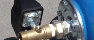
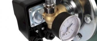
Externally, the pressure gauge resembles a low cylinder of various diameters, most often 50 mm, which consists of a metal body with a glass lid. Through the glass part you can see a scale with marks in pressure units (Bar or Pa). On the side of the housing there is a tube with an external thread for screwing into the hole of the system in which it is necessary to measure the pressure.
When pressure is injected into the medium being measured, the gas or liquid through the tube presses the internal mechanism of the pressure gauge, which leads to a deflection of the angle of the arrow that points to the scale. The higher the pressure created, the more the needle deflects. The number on the scale where the pointer stops will correspond to the pressure in the system being measured.
Pressure that a pressure gauge can measure
Pressure gauges are universal mechanisms that can be used to measure various values:
- Excess pressure.
- Vacuum pressure.
- Pressure differences.
- Atmospheric pressure.
The use of these devices allows you to control various technological processes and prevent emergency situations. Pressure gauges intended for use in special conditions may have additional housing modifications. This may be explosion protection, resistance to corrosion or increased vibration.
Types of pressure gauges
Pressure gauges are used in many systems where there is pressure, which must be at a clearly defined level. The use of the device allows you to monitor it, since insufficient or excessive exposure can harm various technological processes. In addition, excess pressure causes rupture of containers and pipes. In this regard, several types of pressure gauges designed for specific operating conditions have been created.
They are:
- Exemplary.
- General technical.
- Electric contact.
- Special.
- Self-recording.
- Ship's.
- Railway.
The reference pressure gauge is intended for checking other similar measuring equipment. Such devices determine the level of excess pressure in various environments. Such devices are equipped with a particularly precise mechanism that gives minimal error. Their accuracy class ranges from 0.05 to 0.2.
General technical ones are used in general environments that do not freeze into ice. Such devices have an accuracy class from 1.0 to 2.5. They are resistant to vibration, so they can be installed on transport and heating systems.
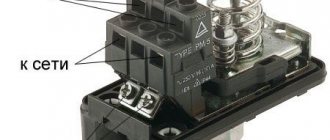
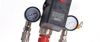
Electrical contact ones are designed specifically for monitoring and warning of reaching the upper limit of a dangerous load that can destroy the system. Such devices are used with various media such as liquids, gases and vapors. This equipment has a built-in electrical circuit control mechanism. When excess pressure appears, the pressure gauge gives a signal or mechanically turns off the supply equipment that pumps the pressure. Also, electric contact pressure gauges may include a special valve that relieves pressure to a safe level. Such devices prevent accidents and explosions in boiler rooms.
Special pressure gauges are designed to work with a specific gas. Such devices usually have colored cases rather than the classic black ones. The color corresponds to the gas with which this device can work. Also, special markings are used on the scale. For example, pressure gauges for measuring ammonia pressure, which are usually installed in industrial refrigeration units, are colored yellow. Such equipment has an accuracy class from 1.0 to 2.5.
Recorders are used in areas where it is necessary not only to visually monitor the system pressure, but also to record indicators. They write a chart that can be used to view pressure dynamics over any period of time. Such devices can be found in laboratories, as well as at thermal power plants, canneries and other food enterprises.
Marine gauges include a wide range of pressure gauges that have a weatherproof housing. They can work with liquid, gas or steam. Their names can be found on street gas distributors.
Railway pressure gauges are designed to monitor excess pressure in mechanisms that serve electric rail vehicles. In particular, they are used on hydraulic systems that move rails when extending the boom. Such devices have increased resistance to vibration. Not only do they withstand shock, but the indicator on the scale does not react to mechanical stress on the body, accurately displaying the pressure level in the system.
Types of pressure gauges based on the mechanism for taking readings of pressure in the medium
Pressure gauges also differ in the internal mechanism that results in taking pressure readings in the system to which they are connected. Depending on the device they are:
- Liquid.
- Spring.
- Membrane.
- Electric contact.
- Differential.
A liquid pressure gauge is designed to measure the pressure of a liquid column. Such devices operate on the physical principle of communicating vessels. Most devices have a visible level of the working fluid from which they take readings. These devices are one of the rarely used. Due to contact with liquid, their interior gets dirty, so transparency is gradually lost, and it becomes difficult to visually determine the readings. Liquid pressure gauges were one of the very first ones invented, but they are still found.
Spring pressure gauges are the most common. They have a simple design that is suitable for repair. Their measurement limits usually range from 0.1 to 4000 Bar. The sensitive element of such a mechanism itself is an oval tube, which contracts under pressure. The force pressing on the tube is transmitted through a special mechanism to a pointer, which rotates at a certain angle, pointing to a scale with markings.
The diaphragm pressure gauge operates on the physical principle of pneumatic compensation.
Inside the device there is a special membrane, the level of deflection of which depends on the effect of the pressure created. Typically, two membranes are soldered together to form a box. As the volume of the box changes, the sensitive mechanism deflects the arrow.
Importance and relevance of pressure gauge classes
When selecting a pressure gauge (the device is usually abbreviated as “DM”) for ordinary living conditions, users rarely pay attention to its error group.
As we have already said, accuracy is not particularly important for such purposes as monitoring mPa (bar, atm) in tires, when it is enough for the user to know the approximate value, or deviations of fractions of divisions or even several marks will not affect the overall picture and condition of the equipment. But high accuracy of readings is always desirable for boilers, heating, water supply, pumps of this equipment and for similar purposes.
And also the accuracy group is one of the parameters that must be paid attention to when the correctness of measurements is especially necessary. For housing and communal services, industry, production, for pressure-sensitive equipment, where a deviation of even one division leads to wear and tear of the equipment, accidents (central water supply systems, heating systems, boiler rooms).
What applies to equipment
Methodological recommendations for the development of state elemental estimate standards for equipment installation and commissioning
APPROVED by order of the Ministry of Construction and Housing and Communal Services of the Russian Federation dated February 8, 2021 No. 78/pr
Appendix 6 List of materials and products that are not subject to inclusion in the elemental estimate standards for installation and are taken into account as equipment 1. Reception devices and control devices (except for single-beam), devices and devices signaling facility fire and security alarm systems. 2. Pipeline shut-off and control valves (valves, gate valves, valves, taps) with a diameter of more than 200 mm, as well as valves with electric, pneumatic, hydraulic, electromagnetic drive, regardless of diameter. 3. Pipeline fittings and pipelines for water and steam from parts, assemblies and blocks with a nominal pressure of over 2.5 MPa for thermal and nuclear power plants. 4. Power and pressure tanks for oil-filled cables. 5. Incentive and water tanks for sprinkler and deluge automatic fire extinguishing systems. 6. Oil and air switches, load switches with drive in open and closed switchgears. 7. Automatic installation switches (automatic). 8. Fittings and fittings for ovens and dryers. 9. Parts, inserts, fittings and blocks with pipeline diaphragms with nominal pressure over 2.5 MPa for nuclear power plants. 10. Bells, local arrow control panels installed at traffic lights. 11. Fire alarm detectors (sensors) (except single action), security alarm detectors (except single action), requiring restoration work after activation. 12. Support and feedthrough insulators for open and closed switchgears, high-voltage support and feedthrough insulators and insulator boxes for the installation of electric precipitators for gas purification. 13. Electrical cables and wires of all brands and sections with finished, cut (according to the diagram) ends, supplied complete with equipment. 14. Distribution columns with switches, fuses or with plug sockets for current over 400 A. 15. Cast columns with remote manual drive for fittings with a diameter of over 200 mm. 16. Compensators with a diameter of over 200 mm. 17. Steel ropes for equipping equipment, supplied complete with equipment. 18. Capacitors and capacitor units for voltages above 100 V. 19. Condensation vessels supplied with diaphragms. 20. Pupinov coils for laying long-distance cable communication lines. 21. Crosses (switchboards). 22. Conveyor (conveyor) belts. 23. Oil (ointments) for filling tanks of oil pumping stations, centralized systems of thick and liquid lubricants, as well as crankcases, gearboxes and bathtubs (except for oil for flushing operations during installation). 24. Transformer oil for installation of transformers, choke transformers and reactors (except for oil used for flushing operations). 25. Turbine oil for filling control systems and bearing units of hydraulic turbines, as well as bearing units and thrust bearings of generators (except for oil for flushing operations during installation). 26. Materials loaded into chemical production equipment: mercury, catalysts (activated carbon, stainless steel rings and shavings, platinum, silver, aluminosilicate, vanadium, chromium, ferrous), reagents. 27. Filter materials for chemical water treatment equipment: anthracite, quartz sand, sulfonated carbon, activated carbon, anion exchange resin, cation exchange resin, Raschig rings. 28. Material resources for filling steam turbine and gas turbine units: oil, ivviol, silica gel, hydrogen, carbon dioxide, inhibited acid. 29. Couplings for oil-filled cables. 30. Tee couplings for cable lines up to 110 kV in mining workings. 31. Factory-made low-voltage complete devices (LVDs): switchboards, points, cabinets, boxes, consoles, control units. 32. Fire extinguishing composition and costs for charging cylinders for chemical fire extinguishing. 33. Car clothing. 34. Electric stoves. 35. Fuses of all types for electrical circuits with voltages over 1 kV or for currents over 400 A. 36. Protection devices installed in transformer and cable boxes, repair cabinets, relay cabinets and on signaling device cabinets: fuses, multiple-acting automatic current switches, arresters and equalizers. 37. Instrumentation, automation and computer equipment. 38. Devices and equipment for video surveillance systems. 39. Counterweights and weights for them for elevators, supplied complete with equipment. 40. Starters for currents over 400 A, as well as oil, magnetic and explosion-proof starters. 41. Explosion-proof manual starters and explosion-proof push-button control stations for mining operations. 42. Circuit breakers and switches for currents over 400 A. 43. Metal mesh for fencing, supplied in prepared form complete with equipment. 44. Relay and crossover cabinets, dispatch control racks. 45. Three-phase electric meters for power networks. 46. Pipes and pipeline assemblies (regardless of diameter) with nominal pressure over 2.5 MPa for nuclear power plants. 47. Input devices (boxes with a three-pole switch and capacitors). 48. Refrigerants, coolants and absorbents. 49. Dust separation cyclones. 50. Primary electric clocks of all types, secondary street clocks, digital electronic clocks, as well as other electrical clock equipment (software time relays, minute pulse broadcast relays, electronic stopwatches with timer output). 51. Busbars for alternating current voltage over 1 kV and direct current voltage over 1.2 kV. 52. Metal battery cabinets with batteries. 53. Factory-installed relay cabinets with plug-in relays. 54. Cabinets with switches for complete distribution devices. 55. Control and regulation cabinets and cabinets with high-speed automatic machines. 56. Laboratory shields with installed equipment. 57. Power switchboards (PSB) and cable cabinets. 58. Boards of line-input code lines. 59. Panels, cabinets, consoles, frames, frames for installing instruments and apparatus (except for those manufactured at construction sites or at enterprises owned by the contractor). 60. Panels, cabinets, boxes of all types with fuses, circuit breakers and switches for currents over 400 A, used on power networks. 61. Explosion-proof cable boxes. 62. Cable boxes for signaling devices, installed on supports.
Pressure gauge is equipment or material
WHAT IS EQUIPMENT AND WHAT IS MATERIALS, HOW TO DETERMINE THIS WHEN DRAFTING ESTIMATE DOCUMENTATION?
When drawing up estimate documentation, material resources are assigned to equipment on the basis of these equipment specifications, which are an integral part of the design documentation. Material resources are classified as construction materials based on specifications of structures, products, and other design documentation data.
The procedure for determining the estimated cost of construction of an object and drawing up estimate documentation based on standards for resource consumption in kind is established in the Instructions on the procedure for determining the estimated cost of construction and drawing up estimate documentation based on standards for resource consumption in kind, approved by the resolution of the Ministry of Architecture and Construction of the Republic of Belarus dated 11/18 .2011 No. 51.
The basis for determining the cost of construction of an object is:
• design assignment issued by the customer, developer;
• design documentation, defect reports for current repair facilities;
• decisions made by the customer, developer and provided for in the design documentation (clause 7 of the above-mentioned Instructions).
When developing design documentation at any design stage, developers determine the necessary equipment, structures, products and materials. At the same time, as part of the design documentation, equipment specifications are filled out in the form established by GOST 21.110-2013 “System of design documentation for construction. Specification of equipment, products and materials" (approved by Resolution of the State Committee for Standardization of the Republic of Belarus dated March 12, 2015 No. 13 (https://tnpa.by/#!/DocumentCard/307505/451624)). The equipment specifications provide the amount of information sufficient for the customer to complete the entire equipment procurement procedure (part one of clause 4.15 of TCP 45-1.02-295-2014 “Construction. Design documentation. Composition and content”, approved by order of the Ministry of Architecture and Construction of the Republic of Belarus dated March 27 .2014 No. 85 (https://tnpa.by/#!/DocumentCard/315341/434817)).
The procedure for determining the estimated cost of equipment, furniture and inventory when determining the estimated cost of construction and drawing up estimate documentation is established by the Methodological Recommendations on the procedure for determining the estimated cost of equipment, approved by Order of the Ministry of Architecture and Construction of the Republic of Belarus dated 05/08/2012 No. 144 (hereinafter referred to as the Methodological Recommendations).
The document is partially displayed. The full text of the document is available for free. If you have paid access, click Login. To obtain paid access, click Buy.
Manometer - a device for measuring pressure
Very often in life, and especially in production, you have to deal with such a measuring device as a pressure gauge.
A pressure gauge is a device for measuring excess pressure. Due to the fact that this value can be different, the devices also have varieties. There are many areas of application for these devices. They can be used in the metallurgical industry, in any mechanical transport, housing and communal services, agriculture, automotive industry and other industries.
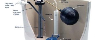
Checking pressure based on water flow
The second way to determine pressure is to perform calculations using data on the amount of water flowing from the tap. In addition to this data, you will also need:
- Find out the configuration of the pipeline and determine what material it is made of;
- Calculate the pipe diameter;
- Determine the intensity of liquid leakage;
- Determine the degree of opening of the tap.
To calculate the pressure, you will need a 3-liter measuring container and a stopwatch. Place the container under the tap and note the time during which it is completely filled with water.
It is possible to determine the approximate pressure after the operation, but the results obtained will be very inaccurate. Indeed, in any case, the jar will be completely filled in less than 10 seconds, which is why the resulting pressure value will be significantly less than according to the regulations. However, you should always start from the fact that a 3-liter container will be completely filled with water in 7 seconds or less. In this case, the pressure inside the pipeline will be closest to the regulated one.
Types and design of the device
Depending on the purposes for which the devices are used, they are divided into different types. The most common are spring pressure gauges. They have their advantages:
- Measuring quantities over a wide range.
- Good technical characteristics.
- Reliability.
- Simplicity of the device.
In a spring pressure gauge, the sensing element is a hollow, curved tube inside. It can have a cross-section in the form of an oval or an ellipsoid. This tube deforms under pressure . It is sealed on one side, and on the other there is a fitting with which the value in the medium is measured. The end of the tube, which is sealed, is connected to the transmission mechanism.
The design of the device is as follows:
- Frame.
- Instrument arrows.
- Gears.
- Axis.
- Leash.
- Gear sector.
A special spring is installed between the teeth of the sector and the gear, which is necessary in order to eliminate backlash.
The measuring scale is presented in Bars or Pascals. The arrow shows the excess pressure of the medium in which the measurement is being taken.
The principle of operation is very simple. The pressure from the medium being measured enters the tube. Under its influence, the tube tries to level out, since the area of the outer and inner surfaces has different sizes. The free end of the tube moves, and the arrow rotates at a certain angle thanks to a transmission mechanism. The measured value and the tube deformation are in a linear relationship. That is why the value that the arrow shows is the pressure of a certain environment.
How to read labels, calculations
The more insignificant the deviations of the DM, the lower the number in its class designation (numerical expression). The range varies, but the most common is 0.4–4.
GOST 2405 defines how it is recommended to designate the device:
Relationship with dimensions
Device type according to class. exact usually associated with the diameter of its graduated part (with the dial). This refers to mechanical devices with an arrow-pointer running along the divisions painted on a given segment.
More details according to GOST 2405:
The same document contains data on the connection between the dial and accuracy classes:
There are also drawings of scales and graduation options:
The diameters of the scales of pressure meters are usually within the following range (in mm): 40, 50, 63, 80, 100, 150, 160, 250.
The values may be different and depend on the standard size according to the agreed specifications with the licensing authorities.
The larger the scale diameter, the smaller the deviations and the lower (better) the accuracy class. The pattern can be traced from the table (see above), for example, a device with Ø50 has groups 2.5 and 4, and a DM with Ø250 has the best (high) accuracy of readings and characteristic smaller values of error groups.
So, the lowest accuracy is for products with a dial Ø40–50, the highest is for standard sizes with a dial Ø160–250.
Dependence on measuring range
Errors depend not only on the classes, but also on the measurement range for which the pressure gauge is designed.
The limits of the pressure gauge's capabilities in terms of the measured value can be any - different manufacturer decisions are allowed. For standard instruments they are extended. But the most standard, statistically average are the following:
Recommended measurement ranges are indicated in GOST R 8.905 in table. adj. A.
How to calculate and determine the class (error) of pressure gauges
Initial data: we have a DM with a range of 10 mPa, group KL 1.5. This means that the greatest possible error of the meter should not be higher than the test result. You can calculate it using the following algorithm:
10×1.5/100=0.15 mPa
You can also find out the maximum deviation as a percentage, this method is consistent with the above formula (0.15 in the example described above is 1.5%). This can be done simply by looking at the class marking number. The number means the following: the greatest error in the pressure gauge readings will be 2.5% of its measurement range.
How to Determine If a Pressure Gauge Is Out of Class
To check whether the level of error is within the assigned class, it is necessary to compare the experimental product with the reference one.
Order:
- Take 2 devices: the reference and the one being tested.
- Measurements are taken with two meters under similar conditions, especially temperature.
- Record the readings. They look at how the readings differ, draw a conclusion about the magnitude of the deviation, and whether it is within the permissible error for the assigned class.
- Carry out the above several times and find the maximum deviation.
The above procedure allows you to assign the meter to a certain accuracy class. In a similar way, manufacturers verify products at factories, but to make the results official, the algorithm is more complex, taking into account many factors, with additional tests. Displayed in journals, procedural acts, certified by seals, signatures of responsible persons, regulated by GOSTs and other regulatory documents. An example of groups of such norms:
We have already described how to calculate the percentage of deviation; here it is also performed as the last step of the verification procedure. For example, the scale range of the test sample was 300 bar, revealing deviations of 3 bar from the reference device. Let's calculate the % error:
3×100/300=1. The result does not exceed 1.
Accuracy class for the above case is 1. If the figure is higher, even by a fraction, then this is the next group.
Types of pressure measurement systems
There are many different pressure gauges for measuring low and high pressure. But their technical characteristics are different. The main distinguishing parameter is the accuracy class. The pressure gauge will show more accurately if the value is lower. The most accurate are digital devices.
According to their purpose, pressure gauges are of the following types:
- Self-recording. They contain a mechanism that allows you to draw a graph of the device’s operation on paper.
- Railway. Used in railway transport.
- Ship's. Used on sea and river vessels.
- Reference. They have a high accuracy class. That is why they are used for testing, adjusting and checking other pressure measuring instruments.
- Special. Used to measure the value of various gases. Depending on what gas they are intended for, they have different body colors and marking letters: for measuring flammable gases - red, for non-flammable gases - black, yellow ammonia (A), white acetylene (Ac), blue oxygen (K).
- Electric contact. They have an electrical alarm that allows you to regulate the measured environment. These devices are divided into two types: based on an electrical contact attachment and with microswitches.
- General technical. Designed to measure pressure in various environments. They can measure excess and vacuum pressures.
Based on the principle of operation, the following types are distinguished:
For which pressure gauges are accuracy classes established?
All pressure gauges positioned as products that meet the standards of GOSTs and other quality regulations have class. exact Let us briefly list the types of devices.
The simplest mechanical pressure meter:
The most common group of DMs is mechanical, also known as deformation, analog.
Mechanical products can be tubular (with a tubular arch-spring, usually single-turn).
This arch is a so-called Bourdon tube, not quite a spring in the traditional sense, but a springy (elastic) arch. The bracket, through the articulation of the levers, at the end of which there is a toothed part, transmits the influence of the measured phenomenon to the pointer gear, moving it along the scale. The mechanism can be supplemented with a regular flat spring.
Strain gauges are also sometimes called "direct gauges".
Analogue DMs include membrane devices, where the main sensitive element is a membrane that responds to pressure. There are also bellows devices, they can be called an improved modification of the latter: the sensitive part is a corrugated (accordion-like) box (chamber), that is, a bellows.
Mechanics include liquid and deadweight pressure gauges. The former have a sensitive element - liquid in the flask, the latter have a special system of counterweights, piston joints.
Deadweight piston products are usually used as exemplary, reference devices:
A separate group of pressure gauges is electrical contact gauges (ECM); they can be mechanical or digital (the latter are usually always like this).
Mechanical ECMs are actually the same spring products, but they have electrical leads for transmitting data to associated control and other equipment.
The third large separate group of types of pressure gauges are digital or electronic. The sensitive elements here are special sensors or the same arc-shaped bow (bracket), spring, membrane, but the readings are interpreted by a microcircuit, which also displays them on the LCD display in numbers, like in calculators.
DMs are also divided into pointer ones and those with results displayed on an LCD display.
There are also the following types of pressure meters:
- exemplary (reference for verification, testing of other such devices);
- highly accurate. Typically these are electronic devices;
- axial, radial.
Below is an example of an exemplary mechanical pressure gauge (the scale is much expanded and, accordingly, especially accurate):
The division into types is not particularly significant for the issue under consideration; the presence of an error class does not depend on the type of device. If this parameter is not specified, it means that the device is not reliable, it is the simplest and cheapest, it is not for serious equipment, not for purposes requiring a certain precision, and its use is extremely undesirable for important tasks.
Types of measuring instruments
Instruments for measuring pressure are divided into the following types:
- Thrust and pressure gauges are pressure and vacuum gauges that have extreme measurement limits of no higher than 40 kPa.
- Traction gauges are a vacuum gauge that has a measurement limit of (-40) kPa.
- A pressure gauge is a pressure gauge of low excess pressure (+40) kPa.
- Pressure and vacuum gauges are devices that are capable of measuring both vacuum and excess pressure in the range of 60–240,000 kPa.
- A vacuum gauge is a device that measures vacuum (pressure that is below atmospheric pressure).
- A pressure gauge is a device that is capable of measuring excess pressure, that is, the difference between absolute pressure and barometric pressure. Its limits range from 0.06 to 1000 MPa.
Most imported and domestic pressure gauges are manufactured according to all generally accepted standards. It is for this reason that it is possible to replace one brand with another.
When choosing a device, you must rely on the following indicators:
- The location of the fitting is axial or radial.
- The diameter of the fitting thread.
- Instrument accuracy class.
- Case diameter.
- Limit of measured values.
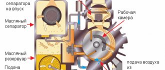
Ionization pressure gauge
Ionization pressure gauges are the most sensitive measuring instruments for very low pressure.
They make measurements indirectly by measuring those ions that are formed when gases are bombarded with electrons. The lower the gas density, the fewer ions will be formed. The calibration of the ionization pressure gauge is unstable. It depends on the nature of the gas being measured. But this nature is not always known. They can be calibrated by comparison with the values of the McLeod pressure gauge, which are independent of chemistry and more stable. Thermoelectrodes with gas atoms collide and regenerate ions. They are attracted to the electrode at a voltage that is suitable for them (this suitable voltage is called a collector). In the collector, the current is proportional to the ionization rate, which in the system is a function of pressure. This is how gas pressure can be determined by measuring collector current.
Most ion pressure gauges are divided into three types:
- Cold cathode.
- Hot cathode. An electrically heated filament produces an electron beam. In this case, electrons pass through the device and ionize gas molecules around them. The ions that are formed accumulate on the electrode with a negative charge.
- A device with a rotating rotor. It is distinguished by its high price and sensitivity.
Calibration of ion pressure gauges is very sensitive to the chemical composition of the measured gases, structural geometry, surface deposits and corrosion. Their calibration may become unusable if switched on in a very low or atmospheric pressure environment.
It is necessary to measure pressure in many industrial sectors, but different instruments are used for this. But regardless of this, this value is not determined by anything other than a pressure gauge.