The section provides information on individual elements of devices, fasteners, installation and clamping units, universal and universal-adjustment devices, calculations of clamping units, mechanized drives, seats, and passport data of metal-cutting machines. Calculation formulas are given for a wide range of clamping device designs.
The information is intended for design engineers and technologists of machine-building plants, design and technological organizations.
Machine tools.
Machine tools are one of the main elements of equipment for metalworking production, allowing the effective use of general-purpose machines in the production process. The use of fixtures makes it possible to specialize and configure machines for given processing processes, ensuring the fulfillment of technological requirements and economically viable productivity. Devices with mechanized control in many cases make it possible to automate the processes of securing and releasing parts, which in many ways brings machines with such devices closer to the operating conditions of specialized equipment. The costs of servicing and repairing devices are fully compensated by the economic effect of their use. Of course, from the above one should not conclude that under all production conditions, machines equipped with accessories can successfully compete with specialized equipment. The degree to which machines are equipped with devices and their choice in each case is decided by the conditions and production program.
Depending on the scale of production (serial, small-scale, individual and experimental) and technological factors, machine tools are divided into the following groups according to their purpose and design.
Universal devices.
Universal devices are designed for installing and securing workpieces of various shapes and sizes. Versatility is achieved by adjusting the installation and clamping elements of the device without changing them. Examples of universal devices include jaw and driver chucks, machine vices, dividing heads, and others. Universal devices are usually used in individual and pilot production. The costs of auxiliary time for servicing universal devices, especially those with manual control, are increased, but in the conditions of the above-mentioned productions these costs are not the main economic factor.
Universal adjustment (adjustable) devices.
Universal adjustment (readjustable) devices are designed for use in conjunction with replaceable adjustment devices, consisting of installation and clamping units. Setting up such devices is characterized by installing an adjustment device to secure a specific workpiece.
Each replaceable adjustment device is designed to serve one operation, although the possibility of using universal adjustment devices to equip several operations is not excluded.
Universal adjustment devices are used when frequent readjustment of machines is necessary. These devices can significantly increase the equipment efficiency of the technological process.
Universal group devices.
Universal group devices are a type of universal adjustment devices and differ from the first ones in that they are designed for installation of workpieces having similar configurations and processing processes.
Collapsible devices.
Prefabricated devices are assembled from standardized components and parts with the calculation of installation and fastening of workpieces of a specific configuration. Such devices are most often used in milling and drilling operations.
Special devices.
Special devices have permanent mounting bases and clamping elements and are designed for installing workpieces of the same shape and size. The designs of special devices should be developed on the basis of maximum use of standard components and parts.
Special devices are used in industries where, due to operating conditions, machines are assigned to a specific operation for a significant period of time.
Universal prefabricated devices (USP) belong to the group of special devices. Unlike conventional special devices, they are reversible, since they are assembled from standardized interchangeable parts and assemblies designed for repeated use. A device assembled from such elements is disassembled after use, and the components and parts are used in new configurations.
USPs are mainly intended for short-term or one-time use. Due to the high cost and some cumbersomeness of the assembled structures, the use of USP in large-scale and mass production is irrational.
To assemble the USP of the required structures, the plant must have a sufficient number of parts and assemblies of the corresponding names. It is believed that for the simultaneous assembly of 200 - 250 different devices, a kit consisting of approximately 20,000 finished parts and assemblies is required, in which:
- basic parts (plates and angles) make up 1%,
- body (supports, pads, prisms) 10%,
- installation and guides 17%,
- fastening and clamping 64%,
- other 6%,
- nodes 2%.
The developed range of parts and assemblies makes it possible to assemble machine tools, welding, control and other types of USP (see figure). To expand the scope of application, the USP may include special elements manufactured for specific operating conditions. The time required to assemble one USP for machining is no more than 2 - 3 hours.
USP parts are manufactured with tight tolerances of mounting surfaces, which ensures sufficient accuracy of installation of workpieces into fixtures. For example, T-shaped and key grooves of base (body) parts, squares, plan washers, which are used for installing fixing and clamping units and parts, are made according to the 2nd class of accuracy, with a deviation from parallelism of no more than 0.01 mm along the length 100 - 200 mm.
The accuracy of machining parts using USP corresponds to classes 2 - 3.
The use of wear-resistant steels for USP parts and proper heat treatment guarantee a long service life.
In a number of industrial areas, bases have been created where, at the request of enterprises, universal prefabricated devices of the necessary designs are assembled and rented out.
State standards have been developed for basic, housing, installation, guides and fasteners with a width of installation grooves of 12 mm (GOST 15185-70 and 15465-70, instead of MN 3655-62 - MN 3866-62), as well as for small-sized ones with a width of grooves 8 mm (GOST 14364-69 and 14607-69).
Main indicators of the USP kit.
| Parts and components | Brand become | Quantity per set in pcs. | Weight in kg | Manufacturing complexity in standard hours | ||
| one details | set | one details | set | |||
| Basic | 12ХНЗА | 200 | 31,4 | 6 280 | 80 | 16 000 |
| Hull | — | 2 000 | 2,7 | 5 400 | 16 | 32 000 |
| Installation | U8A | 2 800 | 0,1 | 280 | 1,5 | 4 200 |
| Guides | 20Х, У12А | 600 | 0,7 | 420 | 3 | 1800 |
| Clamping | 45 | 800 | 1,7 | 1 360 | 3,5 | 2 800 |
| Fastening | 12ХНЗА | 12 000 | 0,2 | 2 400 | 0,7 | 8 400 |
| Others | 1 200 | 0,9 | 1 080 | 3 | 3 600 | |
| Nodes | — | 400 | 5,9 | 2 360 | 27 | 10 800 |
| Total | — | 20 000 | — | 19 580 | — | 79 600 |
Accessories for jig boring machines
Jig boring machines are equipped with numerous devices, measuring and special cutting tools to perform high-precision work. These include a center finder with an indicator, an optical center finder, a center finder mandrel, an installation center, chucks, rotary dividing tables, etc.
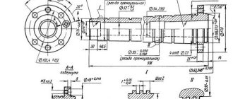
Universal tool holder
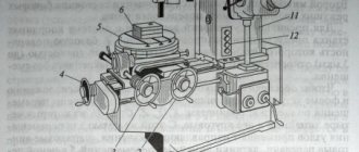
The universal tool holder (boring head) is designed for boring holes and trimming ends during spindle rotation and with automatic radial feed of the cutter.
The tool holder body is fixed in the machine spindle. The slide in which the cutter is secured can move in the housing along dovetail-type guides in the radial direction.
When trimming the end of the body, the tool holder rotates along with the machine spindle. The ring, connected to the ring by a handle, is kept from rotating. The ring contains pins, which, thanks to grooves and balls, can occupy two fixed positions: position E - on and position M - off. The sprocket, being in the tool holder body, rotates with it. When the machine spindle rotates, the sprocket, with its tooth, engages with the pin located in position E and rotates around its axis. The rotation angle of the sprocket axis per spindle revolution is determined by the number of engaged pins. The rotation of the sprocket is transmitted to a worm gear, the worm of which is made in one piece. The hub of the worm wheel is a nut into which a screw is screwed, which, when trimming the end of the part, is fixed in the slider. Consequently, when the worm wheel rotates, the slider will move radially along the stationary screw.
The pins are turned on (position E) and off (position M) when adjusting the tool holder manually, each pin separately, and to prevent the pin from falling out when turned on, there is a shoulder on the ring. There is an oiler at the end of the tool holder shank.
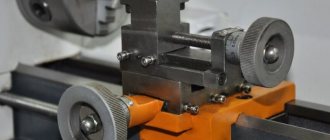
Centerfinder microscope
The microscope-centrefinder is designed to align the edge of the workpiece or any of its points with the axis of the spindle and to set the vertical plane of the workpiece parallel to the travel of the table or slide. The microscope body has a shank with which it is attached to the tapered hole of the machine spindle. The housing contains the optical part of the microscope, consisting of a lens, a prism (mirror), a grid with a crosshair and an eyepiece.
Scheme for aligning the position of the edge of the workpiece relative to the spindle axis. For this purpose, use a test square, which is placed on the workpiece and pressed by hand. The mark applied on the polished horizontal plane facing the microscope must coincide with the direction of the vertical plane of the square. The microscope is installed in the spindle of the machine. By observing the mark on the square through the eyepiece, one achieves an image in which the mark is located in the middle of the overlap. The vertical plane of the mark must coincide with the supporting surface of the square. A large set of various devices are attached to jig boring machines, such as a tool holder with precise feed, a universal tool holder, boring bars, etc.
Center finder with indicator
A center finder with an indicator is designed to align the holes of the workpiece fixed on the machine table with the spindle axis to align the perpendicularity of the end of the workpiece to the spindle axis to install a vertical plane or a generatrix of the cylindrical surface of the workpiece parallel to the table travel or slide.
Selection and preparation of devices.
| Group | Purpose | Degree of reversibility in the production cycle | Preparing fixtures for production |
| Special | Mass and large-scale production | Irreversible | Full design development, manufacturing and debugging |
| Collapsible | Serial production | Components, parts and housing in disassembled form are reversible (allow repeated use) | Assembly and debugging based on standardized components and parts. Partial modification of components is not excluded |
| Universal commissioning | Small-scale production | The main part of the devices is reversible. Replaceable adjustments for special purposes are irreversible | Development, manufacturing and setting up of adjustment devices |
| Universal group | |||
| Universal general purpose | Individual or pilot production | Reversible | Purchased in order of purchase |
| Universal prefabricated USP | Components and parts in disassembled form are reversible | Get rented |
Economic feasibility of equipping machine operations with devices.
The use of devices during machining is economically feasible if the conditions are met
E/Stotal≥1
where E is the amount of expected savings in the workshop cost of processing the part as a result of using the device;
Stotal—the cost of manufacturing and operating the device.
E=[PM(1+a/100)][T'CH'(1+a'/100)]n
where T and T' are the normalized labor intensity of the operation before and after equipping with the device in hours;
Ch and Ch'—tariff hourly rates of the worker before and after equipment in rubles;
a and a' are shop overheads before and after equipment;
n is the number of parts processed using the fixture.
The cost of manufacturing and operating the device can be determined by the formula
Stotal=Sizg+SremK
where Sizg is the workshop cost of manufacturing the device in rubles;
Srem - the cost of one repair during the period of operation of the device for a given batch of parts;
K—number of repairs during the billing period.
The economic feasibility of using USP in mass production is determined by the number of processed parts that is not recouped by the costs of manufacturing and operating a special device. This quantity is found from the inequality:
Accessories for jig boring machines
Jig boring machines are equipped with numerous devices, measuring and special cutting tools to perform high-precision work. These include a center finder with an indicator, an optical center finder, a mandrel-center finder, an installation center, chucks, rotary dividing tables, etc. A center finder with an indicator. It is designed to align the holes of the workpiece fixed on the machine table with the spindle axis to align the perpendicularity of the end of the workpiece to the spindle axis to install a vertical plane or a generatrix of the cylindrical surface of the workpiece parallel to the table travel or slide.
The center finder body is fixed to a ruler, which is installed in the spindle with a conical shank. When testing internal cylindrical surfaces, the probe is pressed against the surface being tested by the force of the indicator spring through a lever. When checking external cylindrical surfaces, the handle with the rod must be pulled out from the center finder body and rotated 90°. In this case, the spring will push the rod forward. The probe will be pressed against the controlled surface by spring force. When checking the ends, the probe is unscrewed and the indicator is secured with the measuring pin down. Alignment diagrams: shapes and locations of various surfaces: internal cylindrical, external cylindrical, horizontal and vertical. Microscope-centrifuge. It is designed to align the edge of the workpiece or any point thereof with the spindle axis and to set the vertical plane of the workpiece parallel to the travel of the table or slide. The microscope body has a shank with which it is attached to the tapered hole of the machine spindle. The housing contains the optical part of the microscope, consisting of a lens, a prism (mirror), a grid with a crosshair and an eyepiece. Scheme for aligning the position of the edge of the workpiece relative to the spindle axis. For this purpose, use a test square, which is placed on the workpiece and pressed by hand. The mark applied on the polished horizontal plane facing the microscope must coincide with the direction of the vertical plane of the square. The microscope is installed in the spindle of the machine. By observing the mark on the square through the eyepiece, one achieves an image in which the mark is located in the middle of the overlap. The vertical plane of the mark must coincide with the supporting surface of the square. A large set of various devices are attached to jig boring machines, such as a tool holder with precise feed, a universal tool holder, boring bars, etc.
The universal tool holder is designed for boring holes and trimming ends during spindle rotation and with automatic radial feed of the tool.
The tool holder body is fixed in the machine spindle. The slide in which the cutter is secured can move in the housing along dovetail-type guides in the radial direction. When trimming the end of the body, the tool holder rotates along with the machine spindle. The ring, connected to the ring by a handle, is kept from rotating. The ring contains pins, which, thanks to grooves and balls, can occupy two fixed positions: position E - on and position M - off. The sprocket, being in the tool holder body, rotates with it. When the machine spindle rotates, the sprocket, with its tooth, engages with the pin located in position E and rotates around its axis. The rotation angle of the sprocket axis per spindle revolution is determined by the number of engaged pins. The rotation of the sprocket is transmitted to a worm gear, the worm of which is made in one piece. The hub of the worm wheel is a nut into which a screw is screwed, which, when trimming the end of the part, is fixed in the slider. Consequently, when the worm wheel rotates, the slider will move radially along the stationary screw.