Modern types of welding open up many possibilities for the master, allowing professionals and amateurs to realize their ideas. Using argon arc welding, you can join dissimilar metals, and using a budget inverter, you can weld a fence in your dacha. But sometimes welding equipment and components for them are not enough for full-fledged work; it is important to learn how to make and understand welding drawings. In them you can find out all the comprehensive information about the metal that needs to be welded, its thickness, characteristics and locations of future joints.
A drawing is a full-fledged document issued for one specific part or an entire metal structure. It contains all the information a welder might need. Reading welding blueprints proficiently is a must-have skill for any welder looking to build a career in the profession. In our article you will learn what is needed to decipher seams in drawings and what signs are used for this, we will also give several examples.
Types of seams and their interpretation
GOST standards for manual arc welding and gas welding distinguish different types of welds and their interpretation. Types of welded joints are designated by letters for easier recording and saving space. There are a butt seam (denoted by the letter “C”), an end seam (also the letter “C”), an overlap (“H”), a T-weld (“T”) and a corner seam (“U”). Let's take a closer look at each type of connection.
A butt welded joint is made at adjacent ends, and the parts to be welded are in the same plane. This type of weld is the strongest and most durable; it is widely used when welding particularly critical metal structures. Before welding, it is necessary to carefully prepare the metal surface and make sure that all parts will be welded in accordance with the drawing.
The end seam, as the name suggests, is formed along the ends of the parts. The side surfaces of the parts are securely connected to each other. The end weld is often used when welding thin metals.
The overlap seam is less demanding on the quality of work than the previous ones. But at the same time, it does not have such good strength characteristics and tolerates loads less well. To make an overlap seam, place the parts parallel, but with a slight offset to the side and partially overlapping each other.
The T-welded connection is one of the toughest and most durable, but does not withstand bending loads well. To make a T-seam, place one part horizontally, the second vertically and weld with the first end facing the surface.
The fillet weld is not used as often as other types of joints. This seam is relatively reliable and durable. One part relative to another can be turned end-to-end and positioned at different angles, depending on the drawing.
All welded joints, regardless of their type, can be single-sided (or as they are called “SS”; this abbreviation is used in drawings around the world) or double-sided (abbreviated “BS”). Single-sided seams are obtained by welding on one side of the part, and double-sided seams are obtained by welding on both sides.
If you need to fusion weld parts, you will need to cut the edges. There are many forms of edge separation; they are characterized by different angles, gap sizes, and so on. The choice of cutting shape depends on the thickness of the metal and the welding method. We have provided some examples of the edge section in the image. You can use any one like in the picture below.
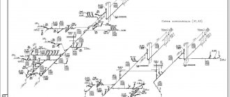
Reading drawings of metal structures
Construction cannot be started and carried out without designing and developing drawings according to which the manufacturing and installation of building structures will take place. In this publication we will share our knowledge and tell you how to read drawings of metal structures.
The first acquaintance with the drawings of metal structures begins with the general information indicated on the first sheet, which indicates the main data of the project and its content. There are always a lot of drawings in a project. Therefore, when we read drawings of metal structures, first of all, we pay attention to their numbers and names.
In addition, it is necessary to familiarize yourself with the general instructions, which indicate standards, GOSTs, SNiPs, SP, in order to determine which fasteners and parts will be used in the project, in what quantities, in what connections they must be installed, as well as under what conditions and with what composition anti-corrosion protection should be carried out. All this information becomes clear to the company specialists involved in the development of the project when we read the drawings of the metal structures.
- Before work on the drawings begins, it is necessary to confirm the economic and technical feasibility of construction using a feasibility study, called a feasibility study.
Our company employs highly qualified specialists who immediately determine the future effectiveness of the project. We work quickly and competently, and most importantly, we read not only our own drawings of metal structures, but also those provided by the customer for carrying out construction and installation work.
True, when we read the drawings of the customer’s metal structures, we encounter various problems. For example, the recommendations for anti-corrosion protection indicate that it should be carried out directly on the construction site. At the same time, Technical Supervision prohibits carrying out such work on a construction site, believing that anti-corrosion protection should be carried out in factory conditions. And metal structures that have not been processed at the construction site have nothing to do with it.
In order to monitor as clearly as possible the safety and durability of construction projects created from light metal structures (LMK or LSTK), it is necessary to understand all the nuances of design. We have said many times that designer mistakes can lead to unpredictable consequences. Information is collected on this site and presented in different sections. To avoid mistakes, we offer turnkey design of metal structures as an optimal cooperation scheme.
- The quality of our products is confirmed by certificates. We guarantee the durability and strength of construction projects erected by our specialists according to our drawings in any climatic zone of Russia in any weather.
We not only read drawings of metal structures, but also work on the project ourselves, including our own design developments, as well as drawings from which non-standard metal structures are manufactured that fit perfectly into the architectural appearance of the building.
In the construction industry, different options for prefabricated buildings are being considered. If this is a multi-storey multifunctional project, the drawings are developed taking into account the location of metal structures at different elevations. We read drawings of metal structures, both multi-story and single-story buildings, regardless of their functional purpose. Moreover, we do not waste time and money on our customers, but carry out our work at fixed prices in the shortest possible time.
- The most difficult thing in the drawings is the arrangement of fastening points for metal structures - beams, braces, trusses.
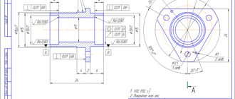
When we read the drawings of the customer’s metal structures, we immediately pay attention to the places where the metal structures of the columns come into contact with the metal structures of the beam. In the drawings in this case, only two numbers will be indicated in a circle, the upper one indicates the number of the node, and the lower number indicates the number of the sheet on which it is drawn.
There are many more points that we pay attention to when we read drawings of metal structures. You can find out more about the terms of cooperation with the customer from our consultants by phone. And after talking with specialists from the design and technical department, you can find out how we read drawings of metal structures. Call! We will be glad to communicate!
Illustration of welds in the drawing
Now let's move on to the conventional images and signs that characterize the seams in the drawings. Welded joints can be visible or invisible. If the seam is invisible, it is shown as a dashed line. If visible, use a solid line. An invisible seam is a seam that is located on the back side of a part, and a visible seam is a seam on the front surface. If the seam is one-sided and the welding is done with the seam facing up, then such a connection is also called a facial connection. If the seam is double-sided, then the connection that was made first is considered the front one. If the edges are symmetrical, then either side can be called the front side.
The one-way arrow shows where the seam line is. On the arrow itself there may be a special “shelf” where an auxiliary sign or letter designating a seam is indicated. Where should the symbols be located - under the “shelf” or above it? It also depends on the type of seam. If the seam is invisible, then under the shelf, and accordingly above it, if visible.
Auxiliary signs
In addition to arrows and letters, auxiliary symbols can be used to indicate welds. Below you can see the standard structure of the symbol, its “skeleton”, on which “muscles” should then appear in the form of letters or other signs.
Auxiliary characters include alphanumeric combinations that contain information about the type of seam and type of connection. This sounds pretty confusing, but here's a quick example: We have the designation C1 and it stands for "single-sided butt weld." C is a letter indicating the type of seam, and 1 is a number indicating the side of welding. Double-sided welding is indicated by the number 2.
Below you can see symbols of seams and joints for some welding methods.
Welding methods also have their own symbol. They are also marked with a letter, this is indicated in regulatory documents. Based on the standards, the welding process indicated on the assembly drawing is carried out.
Below you can see the main welding methods and their designations:
- Automatic submerged arc welding, without the use of flux pads and pads during operation (indicated by the letter “A”).
- Automatic submerged arc welding using a flux pad (“AF”).
- Gas shielded welding using tungsten rods and no wire (“IN”).
- Welding in a shielding gas environment using tungsten rods and using wire (INp).
- Gas shielded welding using consumable rods (“IP”).
- Welding with consumable rods in a carbon dioxide environment (“WW”).
Reading blueprints for dummies: step-by-step instructions
It takes years to accurately understand any design documents. Practice is especially important here: the more you work with them, the simpler and easier it becomes to understand them.
But I have good news for you: if you adhere to a couple of universal rules, you will not experience difficulties in the reading process.
- study the main inscription. It contains all the necessary information: name of the product, scale of the drawing, material of the product, etc.;
- analyze the drawing. Considering all the shapes and lines of the model will help you better imagine it in your head, notice all its features and nuances;
- Please note abbreviations and conventions. This is important because they may contain information that cannot be shown in a picture;
- combine separate parts of one drawing in your imagination. We are talking about complex structures. Be sure to consider each individual piece before combining;
- find a similar model among those you already know. This will help you better understand the element you will have to work with;
- try to determine the sizes of individual elements and the whole object. Dimensional numbers can be preceded by various signs - O (for the shape of a body of rotation), R (radius), □ (square section value), etc.;
- set the surface roughness. You don't need to do anything special. Just look for the corresponding sign (it may be in the upper right corner).
The drawing contains information about the design stage. Pay attention to the letters. P is a technical proposal, E is a sketch stage, T is a technical version, and O is a pilot batch. There are also letters A and B, which indicate an adjusted version based on the experimental batch data and a document made according to the option with the letter A, respectively.
Examples of symbols
To make it clearer for you and you can quickly understand all the notations, we will give several simple and illustrative examples. So, let's begin.
Example No. 1
In the picture above you see a butt seam in which one edge has a curved bevel. The connection itself is double-sided, made by manual arc welding. There is no gain on either side. On the front side the seam roughness is Rz 20 µm, and on the back side it is Rz 80 µm.
Example No. 2
Here you can see that the seam is corner and double-sided, it has no bevels or edges. This connection is made by automatic welding and using flux.
Example No. 3
Here we have a butt seam again, but without bevels or edges. The connection is one-sided, with a lining. The seam is made using heated gas and welding wire.
Example No. 4
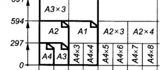
In the fourth example, the seam is a T-joint and has no bevels or edges. It is intermittent and performed using a bilateral method. The seam seems to be in a checkerboard pattern. The work was performed using RDS in a gas environment and using a non-consumable metal rod. The leg of the seam is 6 millimeters, and the length of the seam is 50 millimeters, in increments of 100 millimeters (indicated by the letter “Z”). t w is the length of the seam, and t pr is the length of the step of the intermittent connection.
Example No. 5
In our last example, the seam is overlapped and has no bevels or edges. It is also single-sided and is performed by manual gas-shielded arc welding using a consumable rod. The welded connection is made along an open line. The leg of the seam is 5 millimeters.