One of the most popular methods of joining metal parts using electric current is resistance welding. Despite the fact that it has been used for a century, its capabilities are still not fully exploited. The modes used when carrying out welding work impose strict requirements on the equipment, especially for such a device as a transformer for resistance welding, the characteristics of which determine the quality of the welded joints.
Principle of operation
The technological process of spot welding is quite simple.
The metal parts are pressed tightly against each other, and through short distances a high voltage current is supplied to them using electrodes. As a result, the metal is rapidly heated at the point of contact, and a molten core is formed. Since the parts to be connected are tightly compressed, a diffusion process occurs; after the current supply is stopped, the contact point of the electrodes cools down and the material crystallizes. The connection is so strong that when you try to break it, the metal next to it bursts, but the point of welding remains intact. Welding occurs due to the heating of the metal from a powerful electric pulse passing through it. PHOTO: svarka74.ru
Construction of a contact welding machine
Any equipment for contact welding, industrial or domestic, consists of two main (mechanical and electrical) and one auxiliary units.
Mechanical assembly includes:
- electrodes (in spot welding machines - clamping pliers, in seam welding machines - rollers);
- compression device;
- rotation drive (in seam units);
- compression and upset device (butt welding).
The electrical unit consists of:
- power transformer;
- output voltage regulator;
- secondary circuit;
- primary circuit breaker;
- welding cycle regulator.
Auxiliary blocks:
- pneumohydraulics, containing special filters, lubrication devices for moving parts, a compressed air supply system and pressure regulation;
- water cooling.
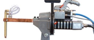
Construction of a homemade resistance welding machine PHOTO: electrikmaster.ru
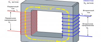
To obtain the required powerful discharge at low voltage, an induction type transformer is required. The correct ratio of windings (primary and secondary) gives an electrical impulse with sufficient power to melt the metal at the point of contact of the electrodes.
Clamping pliers consist of two graphite or copper contacts mounted on different levers and driven by a clamping device. Clamping mechanisms can have different drives:
- Mechanical. The device consists of a lever and a powerful spring, and the compression of the welded workpieces is carried out through the use of the operator’s muscular force. It is used in household factory and home-made units, but does not allow control of the compression force and has low performance.
- Pneumatic. Most often used in portable devices, it is easy to set up by adjusting the pressure in the compressed air supply system. Disadvantages include slow response and the inability to change pressure during the welding process.
- Hydraulic. An unpopular option, it is slow, like a pneumatic drive, but has a wide range of settings, which are realized through the use of adjustable bypass valves.
- Electromagnetic. It is used on both large industrial and manual household units. It is characterized by a high response speed; there is an adjustment for the compression of the workpieces during the working process, which allows for good welding of the metal.
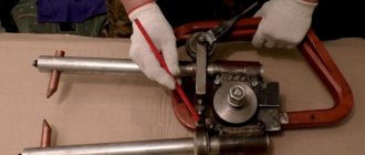
Mechanically driven welder PHOTO: info.zhratsushi.ru
Related article:
Installing electrodes on the welding machine
As already mentioned above, the electrode for resistance welding can be made from a copper rod or a tip from a professional soldering iron, if the power of the device is low. The wire from the device is connected to the electrode using a copper tip, which is connected to it by soldering.
Installing the bottom electrode
The tip is combined with the electrode using a bolted connection, which must be very reliable so that an increase in resistance at the point of unreliable contact does not lead to a loss of power of the spot welding machine. To make such a connection, holes of the same diameter are made in the electrode and tip.
The bolts and nuts with which the electrodes and lugs will be connected to the wires are best chosen from copper or its alloys, which have minimal electrical resistance. Elements of such connections, which greatly simplify the maintenance of the resistance welding machine, are not at all difficult to make with your own hands.
Transformer for welding
Diagram of a transformer for welding.
This structural element operates in arc mode with maximum power.
The transformers used in the design must withstand high current values during operation, the rated strength of which is 200 A. The current-voltage indicators of the transformer must fully comply with the special requirements that ensure the operating modes of arc welding. Some homemade transformer welding machines are simple in their design. They do not have additional devices for adjusting current parameters. Adjustment of the technical parameters of such a device is carried out in several ways:
- using a highly specialized regulator;
- by switching the number of coil turns.
The transformer of the welding unit consists of the following structural elements:
- magnetic circuit made of transformer steel plates;
- two windings - primary and secondary, this transformer component has terminals for connecting devices for adjusting operating current parameters.
Transformer winding diagram.
The transformer used in the welding machine does not have control devices that provide current regulation and limitation on the working winding. The primary winding of the welding transformer is equipped with terminals for connecting control circuits and devices that allow you to configure the welding device depending on operating conditions and parameters of the incoming current.
The main part of the transformer is the magnetic circuit. Most often, when constructing homemade welding machines, magnetic cores from a decommissioned engine or an old power transformer are used. Each magnetic circuit design has its own design nuances. The main parameters characterizing the magnetic circuit are the following:
- magnetic core size;
- number of turns of windings on the magnetic core;
- voltage level at the input and output of the device;
- current consumption level;
- the maximum current received at the output of the device.
These basic characteristics determine the suitability of the transformer for use as a device that promotes the formation of an arc, as well as a device that promotes the formation of a quality weld.
Inverter based
Resistance welding from an inverter is one of the alternative options for using an electronic device at home, the choice of which is determined by the special properties of the manufactured industrial samples of this equipment.
The operating principle of a contact point device based on an inverter is based on the same pulsed heating of the metal in the contact zone, followed by its melting and cooling. That is why its assembly in this case is completely identical to the manufacture of a microwave-based welding machine.
If you don’t have an old microwave device on your household, you can use any transformer suitable for these purposes with a power of at least 1 kilowatt.
The only difference between this option and the previously discussed one is the possibility of using non-rectified pulse current in the inverter circuit.
To securely fix the parts to be welded and prevent them from moving apart and forming a gap, the inverter device uses a special compression mechanism.
How is resistance welding carried out?
Everyone may need to do welding work at home during renovations. The inverter can be useful for installing metal parts or in a mini-workshop at home.
The operating principle of the inverter is as follows:
- the metal is heated by electric current;
- it then melts and solidifies after forming a weld;
- to secure the parts and protect them from moving apart, the parts are compressed by electrodes through which current flows.
To carry out home welding work, you need a powerful power source, and this can lead to overheating of household wires. Check the quality of your wiring in advance and replace it if necessary.
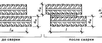
During spot welding, you need to connect two workpieces along adjacent edges. This will be required when installing small parts made of thin material, in particular, metal rods up to 0.5 cm thick.
Connection options
When resistance welding, surfaces can be joined in the following ways:
- continuous reflow;
- intermittent;
- resistance.
When working using melting, you need to connect parts or sheets of metal or heat them with current until melting occurs. This technology is relevant for the following types of work:
- processing of non-ferrous metal or low-carbon steel;
- installation of copper, steel or brass.
However, this method is not particularly popular due to the fact that there are strict temperature requirements, and also because there should be no impurities in the connecting areas.
When continuously melting workpieces, welding pliers and other clamps will be required. The parts are connected when the current is on. When the edges of the parts melt, precipitation will occur, and the current landing will turn off. Thin-walled pipelines are installed in this way, but it is also possible to connect workpieces that differ in structure. The key advantage of the method is efficiency. But there is a risk that metal will leak out along the welding seam and cause waste.
Intermittent reflow is performed with sequential tight or loose contact. Using clamping pliers, the welding line is closed in the area where the workpieces are joined so that the temperature rises to 900-950 degrees. This method is used if the initial power of the device for continuous reflow is insufficient.
Resistance welding solves the following problems:
- the surface for installation is prepared (the contours are cleaned and leveled);
- the edges of the workpieces are connected and secured with clamping parts;
- turns on the current source;
- the edges of the workpieces heat up and melt when the device is running;
- upsetting is performed and the current is turned on.
These types of welding processes differ little from each other in technology, but they differ in the current supply and fastening of parts.
To weld parts using the spot method for domestic needs, you can make the device yourself. Its key mechanisms are:
- clamp;
- device for supplying voltage to capacitors. In it, an electrode is attached to the low-voltage winding.
The second clamping wing is a support wing and can be mounted with large parts.
D.C
As you know, you can assemble a welding unit using either alternating current or direct current. Actually, for the latter, a direct current transformer (DCT) is assembled. We recommend manufacturing such a TFT for semi-automatic units and inverters.
Its advantage is that the arc is easily ignited and, most importantly, stable. A unit with such a transformer will be able to weld parts of any thickness and any type of steel, both stainless steel and cast iron.
Upgrading it into a TFT consists of connecting it to a secondary set of turns of wire - a rectifier. The latter is made using diodes.
The rectifier must use diodes with adequate cooling and its parameters must withstand a current of 200A. We recommend choosing type D161. Next we equalize the current.
We take two capacitors (C1, C2) with the following parameters: 15000 µF, voltage 50V.
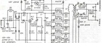
The assembly diagram is shown below. L1 – induction coil for current regulation. X4 – contacts for subsequent connection of the electrode holder. X5 – contacts for connecting ground.
The described scheme has been used for years and continues to show itself on the positive side. Convenient working scheme - use it!
Bottom line
The transformer is the central unit of any welding machine. Its main task is to reduce the voltage and simultaneously increase the current to the required value. Thanks to this, it becomes possible to connect metal products with each other.
The design of the welding transformer is quite simple. At the moment, you can find a large number of implementation schemes for this element on the Internet. So it can be assembled even at home. However, for this it is necessary to correctly calculate the welding transformer.
Areas of application
The area in which electric contact welding is used is quite large - it can also involve massive structures. For example, spacecraft, as well as miniature semiconductors and microcircuits. You can weld parts from almost any metal - high-alloy and low-carbon steels, stainless steels, various alloys. The point method is used in the production of cars, carriages, aircraft, batteries, construction and radio electronics. The thickness of the connected elements varies from a few micrometers to 3 centimeters.
Electric contact seam welding is used to produce moisture-proof containers. Seam welding produces durable joints in the instrument-making industry. Brackets and sheet parts are welded using the relief method. For example, for car body repairs, for attaching door hinges, for connecting fasteners. Electric butt welding has a rather limited scope of application due to the fact that it is difficult to ensure uniform heating of the joints.
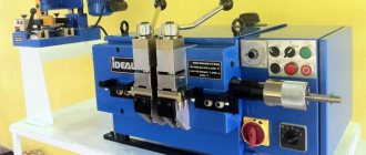
DIY spot welding machine
The welding machine operates on the principles of the Lenz-Juol law: electric current passing through a conductor releases heat, which is directly equal to the square of the current, time and resistance of the conductor. This means that at a current of 1000 A, on thin wires and poorly made connections, the losses will be 10,000 times greater than at 10 A.
Transformer
The main element of any equipment for spot welding is power, with an increased transformation effect (to obtain a normal welding current). It can be taken in a powerful microwave (from 1 kW and above), it powers the magnetron. Convenient for its availability and good characteristics. The transformer’s performance is sufficient for spot welding 1 mm steel sheets. To obtain more power, use 2 or more parts.
The performance of such transformers is up to 2000 V (in a microwave it doubles before being fed to the magnetron), you should not connect them to the network and measure the output characteristics. From this part we need a primary winding (which has a thicker wire and fewer turns) and a magnetic circuit.
The wires are cut with a chisel or a hacksaw (if it is welded and not glued), or they are picked out and drilled out (if the winding is packed very tightly, when knocking it out will destroy everything). When removing the secondary winding wires, try to act carefully so as not to damage the primary winding. There are also shunts in the transformer that limit the current; they also need to be cut off.
After carefully removing the necessary elements, the secondary winding of the transformer is updated. To achieve current ratings of 1000 A, you need to use a copper cable with a cross-sectional thickness of 100 mm² or more. This can be a bundle or stranded wire. If the external insulation prevents you from obtaining the required number of turns, then it is removed and replaced with fabric insulating tape. The wires should be as short as possible to avoid unnecessary resistance.
make more turns, so you will increase the power indicators
For example, if you have 2 transformers with a power of 0.5 kW, with an input voltage of 220 V, with a rated current of 250 A and an output voltage of 2V. By connecting the terminals of the secondary and primary windings, we get a device in which the rated voltage is 2 V, the output current is 500 A (the welding current will also double).
When creating a device, electrodes must be used in the secondary circuits of the device. That is, when using 0.5 kW transformers, they are connected together with wires with a diameter of 1 cm, and the ends are connected to the electrode. If you make a mistake when connecting the terminals of the secondary and primary windings, this will lead to a short circuit.
When you use two powerful transformers and you need to increase the voltage, but the size of the magnetron window does not allow you to add the required number of turns of wire, for this the secondary windings are connected in series. It is necessary to coordinate the direction of the turns, otherwise you can get antiphase, which will lead to an output voltage equal to zero (to correctly understand this point, conduct an experiment with thin leads).
To the primary windings of transformers
The first case indicates that the circuits of the primary and secondary windings are connected together by opposite terminals (the voltage on the primary winding is equal to half the input, which is converted in the secondary winding, where it is summed up and gives a double value). The zero value of the voltmeter shows that the voltage values on the secondary windings are opposite, which means that one of the pairs of windings is connected by the same terminal.
To increase the performance of your spot welding machine, you need to connect several transformers, but they should not exceed the network performance, otherwise the total voltage will drop when using it. Limit yourself to 1000–2000 A; for domestic conditions, this current strength is sufficient.
Electrodes
Copper rods are used as electrodes. The greater the thickness, the better, but its diameter should not be less than that of the wire. If you have a low-power device, then soldering iron tips will do.
The shorter the wire length
When using crimping, the fastening area is much smaller, which increases losses.
Control
On industrial devices it reaches 100 kg
The switch is connected to the primary winding circuit, otherwise it will add resistance, and its contacts will melt during operation.
If you use a lever clamp mechanism, then mount the shutdown button on it. It is very convenient to press the lever with one hand and control the work. The second hand controls the welding of parts.
Subtleties of upgrading a transformer from a microwave oven
To make a secondary winding, you need to wind 2-3 turns on the core, which will ensure an output voltage of about 2 V, and a short-term welding current of more than 800 A. This is quite enough for the effective operation of the spot welding machine. Winding this many turns can be difficult if the wire used has a thick layer of insulation. Solving this problem is quite simple: you need to remove the standard insulation from the wire and wrap it with electrical tape that has a fabric backing. It is very important that the wire used for the secondary winding has the minimum possible length, which will avoid an unreasonable increase in its resistance and, accordingly, a decrease in current strength.
The new secondary winding has taken its place
If you need to weld metal sheets up to 5 mm thick, keep in mind that this will require a spot welder with more power. To make it yourself, you need to use two transformers connected in one circuit. It is imperative to follow the appropriate rules when making such a connection. If you make a mistake and incorrectly connect the terminals of the primary and secondary windings of two transformers, a short circuit may occur. The correct connection of the windings, if there are no markings on their terminals of the same name, is checked using a voltmeter.
After correctly connecting the same terminals of two transformers, it is necessary to measure the value of the current that they jointly generate. As a rule, homemade transformers intended for spot welding machines, which are planned to be used in home workshops, are limited in current strength - no more than 2000 A. Exceeding this value will provoke interruptions in the electrical network not only in your home, but also in your closest neighbors . And this, naturally, will lead to conflicts. The value of the current produced by the connected transformers, as well as the presence of a short circuit in their circuit, is checked using an ammeter.
Another example of spot welding assembly is shown in the video below:
Types of transformers for welding
The technical characteristics of transformers must provide such technical properties that allow heating, melting and joining of processed parts with minimal losses.
The design includes several components:
Transformer core
- A core consisting of several plates made of steel. To assemble the magnetic circuit, plates made of electrical steel are used. One or more windings are installed on it. The voltage is adjusted using a screw pair that passes through the core and winding.
- The metal case is designed to protect the device from any damage. In addition, the transformer includes ventilation devices, handles and wheels for transportation.
The rated operating voltage is 220 or 380 volts and this allows them to be used in industrial facilities and households. The technical characteristics of the transformer allow working with metal workpieces of various shapes and sizes.
The transformer for contact welding consists of the same components as for traditional welding. This equipment operates under short but frequently repeated loads. This results in the windings experiencing severe dynamic loads. To compensate for them, spot welding transformers use an armor-type core and disk windings.
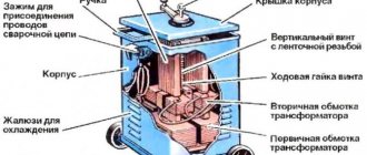
Transformer for contact welding TVK-75
The TVK-75 resistance welding transformer is intended for operation as part of electric welding equipment for spot welding, which are operated indoors under a number of conditions. The magnetic core in this transformer has a tape structure, and is pulled into a frame using studs. The windings of this transformer are disk. For the manufacture of the first winding, heat-resistant PSD cable is used.
Transformer for contact welding TVK-75
The second winding is assembled from separate disks and with the help of metal parts made of copper, they are assembled in a parallel circuit. To cool the secondary winding, running water is used, which moves through specially laid pipes. The windings are filled with epoxy resin. The voltage is regulated using switches that are installed on the welding machine. The main parameters of a transformer of this brand include the following:
Cooled with water, the device is manufactured according to insulation class F. Due to the use of Unicore technology, the transformer suffers minimal losses in the magnetic circuit. The manufacturer produces a transformer in the UHL4 climatic version.
Transformer for resistance welding TKS - 4500 Cascade
Transformer for resistance welding TKS - 4500 Cascade is used for welding parts made of low-carbon steels with a total thickness of up to 4 mm.
Calculation of a transformer for welding
The magnetic core and windings are responsible for creating the operating parameters of the device. That is, knowing what characteristics a transformer should have, you can calculate the parameters of the windings, core and cross-section of all wires.
To perform calculations, you need to take the following data:
DIY welding transformer
- Voltage on the first winding.
- Voltage on the second winding.
- Current strength on the second winding. The size of this parameter is determined by the type of electrodes and the dimensions of the workpiece.
- Core area. This parameter determines the reliability of the transformer as a whole. The optimal size can be considered from 45 to 55 square meters. cm.
- Core window area size. The optimal size is considered to be from 80 to 110 square meters. cm.
- Current density inside the winding. This parameter is responsible for the losses in the winding. For do-it-yourself devices, this characteristic is 2.5 - 3 A.
Design and operation of the control circuit
In a welding machine, the control circuit serves as a kind of time relay. When K1 is turned on for a given time period, the time during which the electrical pulse will affect the parts being welded is thus set. The control circuit includes electrolytic capacitors C1-C6, with a charge voltage of at least 50 volts, P2K switches with independent fixation, as well as KN1 buttons and two resistors R1 and R2.
The capacitance of the capacitors is: for C1 and C2 - 47 μF, C3 and C4 - 100 μF, C5 and C6 - 470 μF. The contacts of the KN1 button should be: one – normally closed, the other – normally open. When the AB1 circuit breaker turns on, the capacitors connected via P2K to the power supply and control circuit begin to charge. Using resistor R1, the initial charging current is limited, and therefore the service life of the containers is significantly increased.
The charging current at this moment flows through the normally closed contact of the KH1 button. After pressing this button, the normally closed contact group opens, after which the control circuit is disconnected from the power supply. Next, the normally open contact group closes, as a result of which the charged containers are connected to relay K1. At this moment, the capacitors are discharged and the connected relay is activated under the influence of current.
Since the normally closed contacts are in an open state, the relay cannot be powered directly from the power supply. The duration of the closed state of contacts 4 and 5 in the MTT4K switch and, accordingly, the duration of the welding pulse depend on the discharge time of the capacitors. After the capacitors are completely discharged, relay K1 is turned off and the welding process stops. To prepare welding for the next cycle, the KH1 button must be released. The discharge of the capacitors itself is carried out through a variable resistor R2, with the help of which the duration of the welding pulse is more accurately regulated.