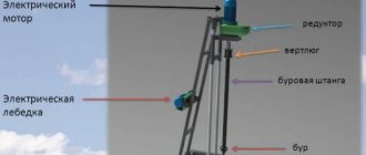
Operating principle and connection of a single-phase 220V electric motor
A single-phase motor operates using alternating electric current and is connected to single-phase networks. The network must have a voltage of 220 Volts and a frequency of 50 Hertz.
Electric motors of this type are used mainly in low-power devices:
Models are available with power from 5 W to 10 kW.
The values of efficiency, power and starting torque for single-phase motors are significantly lower than for three-phase devices of the same size. The overload capacity is also higher for 3-phase motors. Thus, the power of a single-phase mechanism does not exceed 70% of the power of a three-phase mechanism of the same size.
- Actually has 2 phases. but only one of them does the work, so the motor is called single-phase.
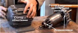
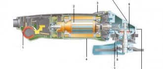
- Like all electric machines. A single-phase motor consists of 2 parts: stationary (stator) and moving (rotor).
- It is an asynchronous electric motor. on the stationary component of which there is one working winding, connected to a single-phase alternating current source.
The strengths of this type of engine include the simplicity of the design, which is a rotor with a squirrel-cage winding. The disadvantages are low starting torque and efficiency.
The main disadvantage of single-phase current is its inability to generate a magnetic field that performs rotation. Therefore, a single-phase electric motor will not start on its own when connected to the network.
In the theory of electrical machines, the rule applies: in order for a magnetic field to arise that rotates the rotor, there must be at least 2 windings (phases) on the stator. It is also required to shift one winding by a certain angle relative to the other.
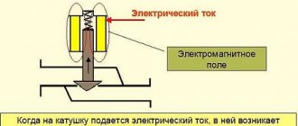
During operation, alternating electric fields flow around the windings:
- According to this. The so-called starting winding is located on the stationary section of the single-phase motor. It is shifted 90 degrees relative to the working winding.
- A current shift can be obtained by including a phase-shifting link in the circuit. Active resistors, inductors and capacitors can be used for this.
- 2212 electrical steel is used as the basis for the stator and rotor.
It is incorrect to call single-phase electric motors that are 2- and 3-phase in structure, but are connected to a single-phase power source through matching circuits (capacitor electric motors). Both phases of such devices are working and are turned on all the time.
Connection diagrams for single-phase electric motors
The question of how to connect a single-phase electric motor very often arises in practice due to the high popularity of using such units for solving various household problems.
The connection diagram for a single-phase electric motor is quite simple and requires taking into account only one fundamental point: to ensure its operation, a rotating magnetic field is necessary. If there is only a single-phase alternating current network at the time of starting the electric motor, it must be formed artificially through the use of appropriate circuit solutions.
Electric motor windings
Laying windings in the stator of a single-phase electric motor
The design of any single-phase electric motor requires the use of at least three coils. Two of them are stator structural elements connected in parallel.
One of them is working, and the second serves as a launcher. Their terminals are located on the motor housing and are used to connect to the network. The rotor winding is short-circuited.
Two of them will be connected to the network, the rest are used for switching.
You can visually identify the working and starting windings by the cross-section of the wire: for the first of them it is noticeably larger. You can measure the resistance with a tester by connecting it to the terminals: at the working winding its value will be less. As a rule, the resistance of the windings will be no more than several tens of ohms.
Features of torque formation
The magnetic field created by the motor coils has a phase shift of 90 degrees. This is usually achieved through a capacitor that is connected in series with the trigger circuit. Possible connection options are shown in the figure below.
Options for creating a phase shift
The trigger coil can operate continuously. A scheme based on its shutdown after reaching the rated rotor speed is also acceptable. The permanent connection of the starting winding complicates the design of the motor, but improves its performance. These differences do not affect the characteristics of connecting to the network.
A single-phase electric motor allows you to simply change the direction of shaft rotation to the opposite direction. To do this, the phase of the current coming from the network and flowing through the starting circuit is shifted to the opposite one. This procedure is implemented by simply changing the order in which the starting winding is turned on when it is connected to the working winding.
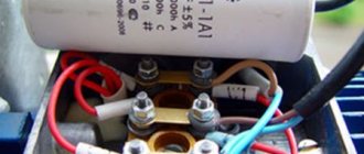
Capacitors
Source: https://ElectricVDele.ru/elektrooborudovanie/elektrodvigateli/shema-podklyucheniya-odnofaznogo-elektrodvigatelya.html
Main types of single-phase induction motors
Household appliances and low-power devices operate on single-phase alternating current; in addition, three-phase power supply cannot be provided everywhere. Therefore, single-phase AC motors have become widespread, especially in the USA. AC motors are often preferred due to their robust design, low cost, and maintenance-free operation.
As the name suggests, a single-phase induction motor operates on the principle of induction; the same principle applies to three-phase electric motors. However, there are differences between them: single-phase electric motors, as a rule, operate at alternating current and voltage 110 -240 V, the stator field of these motors does not rotate. Instead, each time the sinusoidal voltage jumps from negative to positive, the poles change.
In single-phase electric motors, the stator field is constantly aligned in one direction, and the poles change their position once in each cycle. This means that a single-phase induction motor cannot be started on its own.
In theory, a single-phase electric motor could be started by mechanically rotating the motor and then immediately applying power. However, in practice, all electric motors start automatically.
There are four main types of electric motors:
• induction motor with capacitor start / winding operation (inductance) (CSIR),
• induction motor with capacitor start/capacitor operation (CSCR),
• rheostatic starting induction motor (RSIR) and
• permanent split capacitance (PSC) motor.
The figure below shows typical torque/speed curves for the four main types of single-phase AC motors.
How to connect a 220V asynchronous motor
Since the supply voltages for different consumers may differ from each other, there is a need to reconnect electrical equipment. Making the connection of a 220-volt asynchronous motor safe for further operation of the equipment is quite simple if you follow the proposed instructions.
In fact, this is not an impossible task. In short, all we need is to connect the windings correctly. There are two main types of asynchronous motors: three-phase with a star-delta winding, and motors with a starting winding (single-phase). The latter are used, for example, in Soviet-designed washing machines. Their model is AVE-071-4C. Let's look at each option in turn.
- Three-phase
- Switch to desired voltage Increase voltage
- Voltage reduction
Photos of single-phase electric motors
Characteristics of electric motors: main parameters and explanation of the markings of modern electric motorsCapacitor for an electric motor: selection tips and rules for connecting a starting capacitor
DC electric motor: device and principle of operation. Main features of use and labeling
Read here! Do-it-yourself electric motor: instructions for assembling a homemade mechanism. Possible modifications and simplest models
Connection diagrams
For those who are a little unfamiliar with how asynchronous electric motors are connected to a three-phase network, I strongly recommend that you read my article Connecting a motor via a magnetic contactor. I assume that the reader knows how the electric motor turns on, why and what kind of motor protection is needed, so in this article I omit these questions.
In theory everything is simple, but in practice you have to rack your brains.
Obviously, turning on the Dahlander motor windings can be done in two ways - through a switch and through contactors.
Changing speeds using a switch
Let's first consider a simpler circuit - through a PKP-25-2 type switch. Moreover, these are the only schematic diagrams that I have come across.
The switch must have three positions, one of which (middle) corresponds to the engine being turned off. About the switch device - a little later.
Connecting a two-speed motor. Diagram on the control panel switch.
Crosses on the dotted lines of the SA1 switch position indicate the closed states of the contacts. That is, in position 1, power from L1, L2, L3 is supplied to the triangle (pins U1, V1, W1). Pins U2, V2, W2 remain unconnected. The engine rotates at the first, reduced speed.
When SA1 is switched to position 2, the pins U1, V1, W1 are connected to each other, and power is supplied to U2, V2, W2.
Switching speeds using contactors
When started using contactors, the circuit will look similar:
Scheme of switching on the motor at different speeds using contactors
Here, the motor turns on the contactor KM1 at the first speed, and KM2 at the second speed. It is obvious that physically KM2 must consist of two contactors, since it is necessary to close five power contacts at once.
Electric motor connection diagram
The connection diagram of the electric motor is largely determined by its operating conditions. For example, a star connection provides smoother operation, but results in a loss of power compared to a delta connection.
Sometimes it is necessary to connect a three-phase motor to a single-phase network. In any case, this issue must be considered in order. (Hereinafter, we will talk about the asynchronous electric motor as the most common one).
Figure 1 shows two diagrams for connecting motor windings.
- Star connection diagram.
The beginnings (or ends) of all windings are connected at one point, the remaining ends (or beginnings) are each connected to their own phase (L1, L2, L3). This circuit does not allow the electric motor to be used at full power, but has a lower starting current. - Connection of electric motor windings with a triangle.
In this case, the beginning of one winding is connected to the end of the other. The vertices of the resulting triangle are connected to a three-phase current circuit. Unlike a star connection, this circuit allows you to use the entire rated power of the motor, but has a higher starting current. - Connecting the motor to the network is the same, regardless of the method of connecting the windings, therefore, when talking about its various connections, I will use the electric motor designation given here so as not to once again complicate the understanding of the circuit.
The motor is connected to the network through an electromagnetic starter. Diagrams of such connections are given here.
The motor windings are connected to one circuit or another by appropriately installing jumpers in the terminal box. (See the corresponding pictures below the connection diagrams). For those who are accustomed to understanding everything thoroughly, the lower part of Figure 1.c shows a diagram of connecting the electric motor windings to the corresponding terminals.
It should be noted that the above applies to motors that have not undergone modifications (repairs) and have standard winding markings.
Otherwise, you need to independently find the windings, their beginnings and ends. Figure 2 explains how to do this.
- We call the windings. To do this, connect one multimeter probe in resistance measurement mode to any terminal (terminal), and use the other to sequentially check the rest. Points, the resistance between which is units or fractions of ohms (close to zero), are the terminals of one winding.
- We mark the found winding, similarly ring the remaining conclusions, and find the rest.
- We determine the beginnings and ends of the electric motor windings.
To do this, we connect any two in series and apply alternating voltage to them. For safety, it is better to limit it to 12-36 Volts. To the remaining one we connect a multimeter in AC voltage measurement mode. The presence of voltage indicates that the windings are connected in phase, that is, the end of one is connected to the beginning of the other. This option is exactly shown in the figure. The absence of voltage indicates that the windings are connected at their ends (or beginnings). We mark them accordingly. We repeat these steps for the remaining winding connected to any of the first two.
Connecting a single-phase asynchronous motor
To accelerate an asynchronous motor, it is necessary to create a rotating magnetic field. This is easily handled by a three-phase power supply, where the phases are shifted relative to each other by 120 degrees. But if we are talking about how to connect a single-phase electric motor, then a problem arises: without a phase shift, the shaft will not begin to rotate.
Inside a single-phase asynchronous motor there are two windings: starting and working. If a phase shift is provided in them, the magnetic field will become rotating. And this is the main condition for starting the electric motor. The phases can be shifted by adding resistance (resistor) or an inductive coil. But the most commonly used capacitors are starting and/or running capacitors.
With starting capacity
In most cases, the circuit only includes a starting capacitor. It is active only when the engine is starting. Therefore, the method is good when the launch promises to be difficult, otherwise the shaft will not be able to accelerate due to the small initial torque. After acceleration, the starting capacitor is turned off and operation continues without it.
The connection diagram for a motor with an auxiliary tank is shown in the figure above. To implement it, you will need a relay or at least one button, which you will press for 3 seconds while starting the motor. The auxiliary capacitor, together with the auxiliary winding, is included in the circuit only for a while.
This arrangement provides optimal starting torque if minor AC surges occur during startup. But there is also a drawback - when operating in nominal mode, the technical characteristics drop. This is due to the shape of the magnetic field of the working winding: it is oval, not circular.
With working capacity
If the start is easy, but the work is hard, then instead of a starting capacitor you will need a working capacitor. The connection diagram is shown below. The peculiarity is that the working capacitance, together with the working winding, is constantly connected to the circuit.
The circuit provides good performance when operating in nominal mode.
With both capacitors
A compromise solution is to use auxiliary and working tanks simultaneously. This method is ideal if the AC motor is already started with a load, and the work itself is difficult for it. Look, the diagram below is like two diagrams (with working and auxiliary capacitance) superimposed on each other. When starting, the trigger will be turned on for a few seconds, and the second drive will be active all the time: from start to shutdown.
Capacity calculation
The greatest difficulty for beginners is calculating the capacitance of capacitors. Professionals select them empirically, listening to the engine during startup and operation. This is how they determine whether the drive is suitable or whether they need to look for another one. But with a small error in most cases, the capacity can be calculated as follows:
- For a working drive: 0.7-0.8 µF per 1000 watts of electric motor power;
- For the starting capacitor: 2.5 times more.
Example: you have a 2 kW asynchronous single-phase electric motor. This is 2000 watts. This means that when connecting with a working capacitance, you need to stock up on a 1.4-1.6 µF drive. For the starting one you will need 3.5-4 uF.
Connecting a single-phase synchronous electric motor
Despite the complexity of the design of synchronous motors, they have many advantages over asynchronous ones. The main thing is the low sensitivity to voltage surges leading to a sharp decrease or increase in current. No less significant is the fact that synchronous motors can operate even with overload, not to mention the optimal mode of reactive energy and shaft rotation at a constant speed. However, connecting is a labor-intensive process, and this is already a disadvantage.
Overclocking method
You cannot start a single-phase synchronous motor by simply applying power to its windings. Because at the moment of switching on, the direction of the supply current in the stator windings corresponds to figure (a). At this time, a pair of forces acts on the rotor, which is still at rest, which will try to rotate the shaft clockwise. But after half the period in the stator windings, the current will change its direction. Therefore, a pair of forces will already act in the opposite direction, turning the shaft counterclockwise, as in figure (b). Since the rotor has great inertia, it will never move.
To make the rotor rotate, it is necessary that it has time to make at least half a revolution so that a change in the direction of the current does not affect its rotation. This is possible if the shaft is accelerated with the help of outside forces. This can be done in two ways:
- Manually;
- Using a second engine.
Only low-power synchronous electric motors can be accelerated with your own hand strength. And for medium- and high-power units you will have to use a different motor.
When accelerating with an external force, the rotor begins to rotate at a speed close to synchronous. Then only the excitation winding turns on, and then the stator winding.
Asynchronous start of a synchronous motor
If metal rods are placed in the tips on the rotor poles, and they are connected to each other on the sides by rings, then the motor must be started asynchronously. These rods play the role of an auxiliary winding that an asynchronous motor has. In this case, the excitation winding is short-circuited using a discharge resistor, and the stator winding is connected to the network. This is the only way to achieve the same acceleration as an asynchronous electric motor. But after the rotation speed is as close as possible to synchronous (95% of it is enough), the excitation winding is connected to a direct current source. The speed becomes completely synchronous, which entails a decrease in the induced emf of the auxiliary winding down to zero. And it turns off automatically.
The layout and method of connecting your motor will depend on whether you have a synchronous or asynchronous motor. The power of the motor is also taken into account, as well as the starting method: with or without load. A basic understanding of mechanics and electromagnetic phenomena will help you understand the drawings.
Electric motor connection diagram. Connecting a single-phase electric motor
Technologies October 14, 2017
There are several schemes for connecting electric motors. It all depends on what type of machine is used. In everyday life, every person uses many electrical appliances; about 2/3 of the total number have electric motors of varying power with different characteristics in their design.
Typically, when instruments fail, motors can continue to operate. They can be used in other designs: make homemade machines, electric pumps, lawn mowers, fans. But now you need to decide which circuit to use to connect to a household network.
Electric motor design and connection
In order to use electric motors for homemade devices, you need to connect the windings correctly. The following machines can be connected to a single-phase 220 V household network:
- Asynchronous three-phase electric motors. Electric motors are connected to the network using a “triangle” or “star” connection.
- Asynchronous electric motors operating from a single-phase network.
- Brushed motors equipped with a brushed design to power the rotor.
All other electric motors must be connected using complex starting devices. But stepper motors must be equipped with special electronic control circuits. Without knowledge and skills, as well as special equipment, it is impossible to make a connection. It is necessary to use complex circuits for connecting electric motors.
Single and three phase network
The household network has one phase, the voltage in it is 220 V. But you can also connect three-phase electric motors designed for a voltage of 380 V to it.
Basic connection diagrams
As a phase-substituting element for connecting a single-phase asynchronous motor, you can use various electromechanical elements (inductor, active resistor, etc.), but a capacitor provides the best starting effect, which is why it is used for this most often.
single phase asynchronous motor and capacitor
There are three main ways to start a single-phase asynchronous motor through:
- worker;
- launcher;
- working and starting capacitor.
In most cases, a circuit with a starting capacitor is used. This is due to the fact that it is used as a starter and only works when the engine is turned on. Further rotation of the rotor is ensured by the pulsating magnetic field of the working phase, as already described in the previous paragraph. A relay or button is often used to complete the trigger circuit.
Since the starting phase winding is used for a short time, it is not designed for heavy loads and is made of thinner wire. To prevent its failure, a thermal relay (opens the circuit after heating to the set temperature) or a centrifugal switch (turns off the starting winding after acceleration of the motor shaft) is included in the motor design.
In this way, excellent starting characteristics are achieved. However, this scheme has one significant drawback - the magnetic field inside a motor connected to a single-phase network is not circular, but elliptical. This increases losses during the conversion of electrical energy into mechanical energy and, as a result, reduces efficiency.
The circuit with a working capacitor does not provide for disconnecting the additional winding after starting and accelerating the engine. In this case, the capacitor allows you to compensate for energy losses, which leads to a natural increase in efficiency. However, in favor of efficiency, starting characteristics are sacrificed.
For the circuit to operate, it is necessary to select an element with a certain capacity, calculated taking into account the load current. An unsuitable capacitor will cause the rotating magnetic field to take on an elliptical shape.
A kind of “golden mean” is a connection diagram using both capacitors - both starting and working. When connecting the engine in this way, its starting and operating characteristics take average values relative to the circuits described above.
In practice, for devices that require the creation of a strong starting torque, the first circuit with a corresponding capacitor is used, and in the opposite situation, the second, with a working one.
How to connect
You can connect a single-phase electric motor to a power outlet using special connectors - a plug. It is necessary to have a voltage of 220 - 240 V and a current frequency of 50 Hz. Regardless of what kind of device it is - a juicer, mixer, electric meat grinder or vacuum cleaner, the connectors of the connected electrical appliance and sockets always match!
The electric motor can be started using a capacitor of the correct capacity, connected to the starting winding, or using a resistor.
Usually all this is already provided for in the design. Just “plug the plug into the socket” and press the “start” button.
At the same time, the trigger mechanism can operate either briefly or be permanently connected to the circuit.
Thus, when choosing a purposeful “motor” for a single-phase network, it is important to start it correctly. Household appliances already have the necessary settings, just press a button
In other cases, you need to choose the right starting device so that the engine starts and performs its assigned tasks.
Connection
To operate the device, 1 phase with a voltage of 220 Volts is required. This means that you can plug it into a household outlet. This is precisely the reason for the popularity of the engine among the population. All household appliances, from a juicer to a grinder, have mechanisms of this type.
connection with starting and running capacitors
There are 2 types of electric motors: with a starting winding and with a working capacitor:
- In the first type of devices. The starting winding operates via a capacitor only during start-up. Once the machine reaches normal speed, it turns off and operation continues with one winding.
- In the second case. for motors with a working capacitor, the additional winding is permanently connected through the capacitor.
An electric motor can be taken from one device and connected to another. For example, a working single-phase motor from a washing machine or vacuum cleaner can be used to operate a lawn mower, processing machine, etc.
There are 3 schemes for switching on a single-phase motor:
- In 1 scheme. The work of the starting winding is performed by means of a capacitor and only for the start-up period.
- 2 circuit also provides for a short-term connection, but it occurs through a resistance and not through a capacitor.
- Scheme 3 is the most common. In this scheme, the capacitor is constantly connected to a source of electricity, and not just during startup.
Connecting an electric motor with starting resistance:
- The auxiliary winding of such devices has increased active resistance.
- To start an electrical machine of this type, a starting resistor can be used. It should be connected in series to the starting winding. Thus, it is possible to obtain a phase shift of 30° between the winding currents, which will be quite enough to start the mechanism.
- Besides. a phase shift can be obtained by using a starting phase with a higher resistance value and a lower inductance value. This winding has fewer turns and thinner wire.
Connecting a motor with capacitor start:
- For these electric machines, the starting circuit contains a capacitor and is turned on only for the start period.
- To achieve the maximum starting torque, a circular magnetic field is required that performs the rotation. For it to occur, the winding currents must be rotated 90° relative to each other. Phase-shifting elements such as a resistor and inductor do not provide the necessary phase shift. Only the inclusion of a capacitor in the circuit allows you to obtain a phase shift of 90°, if you select the capacitance correctly.
- Calculate. Which wires belong to which winding can be determined by measuring the resistance. For the working winding, its value is always less (about 12 Ohms) than for the starting winding (usually about 30 Ohms). Accordingly, the cross-section of the working winding wire is larger than that of the starting winding.
- The capacitor is selected according to the current consumed by the motor. For example, if the current is 1.4 A, then a capacitor with a capacity of 6 μF is required.
Connection diagram for a single-phase motor with a starting winding
How to determine the working and starting windings of a single-phase motor
Single-phase motors are low-power electrical machines. The magnetic circuit of single-phase motors contains a two-phase winding, consisting of a main winding and a starting winding.
Two windings are needed to cause the rotor of a single-phase motor to rotate. The most common motors of this type can be divided into two groups: single-phase motors with a starting winding and motors with a running capacitor.
For engines of the first type, the starting winding is switched on through a capacitor only at the time of start-up and after the engine has developed a normal rotation speed, it is disconnected from the network. The motor continues to operate with one working winding. The size of the capacitor is usually indicated on the motor nameplate and depends on its design.
For single-phase asynchronous AC motors with a running capacitor, the auxiliary winding is permanently connected through a capacitor. The value of the working capacitance of the capacitor is determined by the design of the engine.
That is, if the auxiliary winding of a single-phase motor is starting, its connection will occur only during the start-up, and if the auxiliary winding is a capacitor, then its connection will occur through a capacitor, which remains turned on during engine operation.
It is necessary to know the design of the starting and operating windings of a single-phase motor. The starting and operating windings of single-phase motors differ in both the cross-section of the wire and the number of turns. The working winding of a single-phase motor always has a larger wire cross-section, and therefore its resistance will be less.
Look at the photo and you can clearly see that the wire cross-sections are different. The winding with a smaller cross-section is the starting one. You can measure the resistance of the windings using dial and digital testers, as well as an ohmmeter. The winding with less resistance is the working one.
Rice. 1. Working and starting windings of a single-phase motor
Now here are a few examples you may encounter:
Advice
If the motor has 4 terminals, then having found the ends of the windings and after measuring, you can now easily figure out these four wires, less resistance is the working one, more resistance is the starting one. Everything is connected simply, 220V is supplied to the thick wires.
And one end of the starting winding, for one of the workers. On which of them there is no difference, the direction of rotation does not depend on it. It also depends on how you insert the plug into the socket.
The rotation will change depending on the connection of the starting winding, namely, by changing the ends of the starting winding.
Next example. This is when the motor has 3 terminals. Here the measurements will look like this, for example - 10 ohms, 25 ohms, 15 ohms. After several measurements, find the tip from which the readings, with two others, will be 15 ohms and 10 ohms. This will be one of the network wires.
The tip that shows 10 ohms is also the network one and the third 15 ohm will be the starting one, which is connected to the second network one through a capacitor. In this example, the direction of rotation, you will not change what it is and will be.
Here, in order to change the rotation, you will need to get to the winding diagram.
Another example when measurements can show 10 ohms, 10 ohms, 20 ohms. This is also one of the types of windings. These came on some models of washing machines, and not only that.
In these motors, the working and starting windings are the same (according to the design of three-phase windings). It makes no difference what kind of working winding you have and what kind of starting winding. Connecting the starting winding of a single-phase motor.
also carried out through a capacitor.
Source: https://studvesna73.ru/07/23/5772/
Operating principle
The principle of operation of an electric motor demonstrates the simplest experiment that we were all shown at school - the rotation of a frame with current in the field of a permanent magnet.
The frame with current is an analogue of the rotor, the stationary magnet is the stator. If current is applied to the frame, it will turn perpendicular to the direction of the magnetic field and freeze in this position. If you force the magnet to spin, the frame will rotate at the same speed, that is, synchronously with the magnet. We have a synchronous electric motor. But our magnet is a stator, and by definition it is motionless. How to make the magnetic field of a stationary stator rotate?
First, let's replace the permanent magnet with a current-carrying coil. This is the winding of our stator. As is known from the same school physics, a coil with current creates a magnetic field. The latter is proportional to the magnitude of the current, and the polarity depends on the direction of the current in the coil. If we apply alternating current to the coil, we get an alternating field.
A very clear analogy with a clock will help us. What vectors constantly rotate before our eyes? These are the hour hands. Let's imagine that there is a clock hanging in the corner of the room. The second hand rotates one full revolution per minute. An arrow is a vector of unit length.
The shadow that the arrow casts on the wall varies as a sine with a period of 1 minute, and the shadow cast on the floor changes as a cosine. Or a sine phase shifted by 90 degrees. But a vector is equal to the sum of its projections. In other words, the arrow is equal to the vector sum of its shadows.
Connection diagrams for single-phase asynchronous motors
With starting winding
To connect a motor with a starting winding, you will need a button in which one of the contacts opens after switching on. These opening contacts will need to be connected to the starting winding. In stores there is such a button - this is PNDS. Its middle contact closes for the holding time, and the two outer ones remain in a closed state.
Appearance of the PNVS button and the state of the contacts after the “start” button is released"
First, using measurements, we determine which winding is working and which is starting. Typically the output from the motor has three or four wires.
Consider the option with three wires. In this case, the two windings are already combined, that is, one of the wires is common. We take a tester and measure the resistance between all three pairs. The working one has the lowest resistance, the average value is the starting winding, and the highest is the common output (the resistance of two windings connected in series is measured).
If there are four pins, they ring in pairs. Find two pairs. The one with less resistance is the working one, the one with more resistance is the starting one. After this, we connect one wire from the starting and working windings, and bring out the common wire. A total of three wires remain (as in the first option):
- one from the working winding is working;
- from the starting winding;
- general.
We work further with these three wires - we use them to connect a single-phase motor.
With all these
- Connecting a single-phase motor with a starting winding via the PNVS button
connecting a single-phase motor
We connect all three wires to the button. It also has three contacts. Be sure to place the starting wire on the middle contact (which closes only during the start), the other two - on the outer ones (arbitrarily)
We connect a power cable (from 220 V) to the extreme input contacts of the PVNS, connect the middle contact with a jumper to the working one (note! not to the common one). That's the whole circuit for switching on a single-phase motor with a starting winding (bifilar) through a button
Condenser
When connecting a single-phase capacitor motor, there are options: there are three connection diagrams and all with capacitors. Without them, the engine hums, but does not start (if you connect it according to the diagram described above).
Connection diagrams for a single-phase capacitor motor
The first circuit - with a capacitor in the power supply circuit of the starting winding - starts well, but during operation the power it produces is far from rated, but much lower. The connection circuit with a capacitor in the connection circuit of the working winding gives the opposite effect: not very good performance at start-up, but good performance. Accordingly, the first circuit is used in devices with heavy starting (concrete mixers, for example), and with a working condenser - if good performance characteristics are needed.
Circuit with two capacitors
There is a third option for connecting a single-phase motor (asynchronous) - install both capacitors. It turns out something between the options described above. This scheme is implemented most often. It is in the picture above in the middle or in the photo below in more detail. When organizing this circuit, you also need a PNVS type button, which will connect the capacitor only during the start time, until the motor “accelerates”. Then two windings will remain connected, with the auxiliary winding through a capacitor.
Connecting a single-phase motor: circuit with two capacitors - working and starting
When implementing other circuits - with one capacitor - you will need a regular button, machine or toggle switch. Everything connects there simply.
Selection of capacitors
There is a rather complex formula by which you can calculate the required capacity accurately, but it is quite possible to get by with recommendations that are derived from many experiments:
- The working capacitor is taken at the rate of 70-80 uF per 1 kW of engine power;
- starting - 2-3 times more.
The operating voltage of these capacitors should be 1.5 times higher than the network voltage, that is, for a 220 volt network we take capacitors with an operating voltage of 330 V and higher. To make starting easier, look for a special capacitor for the starting circuit. They have the words Start or Starting in their markings, but you can also use regular ones.
Connecting a single-phase motor
Before you start connecting any electric motor, you must be completely sure that the motor is working. Carry out a full inspection to check the quality of the bearings and the absence of play in the rotor seats and in the engine covers. Check the windings for short circuits between each other and the housing.
Also, when connecting, you must follow safety precautions, be extremely careful and work without haste.
To connect a single-phase electric motor with a starting winding, we need a switch with a starting contact - PNVS. The number after the letters indicates the current strength for which the switch is designed.
note
In the previous article, I told you how to determine the type of motor, whether it is three-phase or single-phase.
And if you doubt whether it is a capacitor motor or one with a starting winding, then you must first connect the motor as with a starting winding, and if it does not start, then it is a capacitor motor.
In order to find out which of the two windings is working, it is necessary to measure their resistance. The coil that has the least resistance is the working one. The exception is a very small percentage of capacitor motors, in which both the working winding and the capacitor winding are the same and have the same resistance.
The starting winding is connected only to start the engine and is turned off after the engine has picked up speed. Only the working winding remains in operation. A correctly wound engine, with an inspection carried out without load on the shaft, reaches the required speed in no more than a few seconds, but more often - instantly. Therefore, during a test run, the engine must be securely fastened.
To start a motor with a starting winding, you need to connect it according to the following diagram:
We connect one end of the working and starting ends together and connect it to one of the extreme marks of the button. This will be the common wire. We connect the second end of the working winding to the second extreme mark of the button. And we connect the remaining wire of the trigger coil to the middle mark of the button.
In this case, we use the stamps on only one side of the button. Three marks on the other side remain free for now. We connect the power cord to the outer two of them. And to the central mark we connect a jumper from the outer mark opposite which one working wire is connected.
We close the button cover, secure the motor, do a test switch on and off the button to make sure it is working and to know that it is in the off state. We plug the plug into the socket, press the start button and hold it until the engine speeds up.
Important
But no more than a few seconds. Then release the button. If the motor hums but does not start to rotate, then the motor is a capacitor motor and must be connected according to a different circuit.
To connect a capacitor motor, a start button is not needed.
Therefore, any starter, toggle switch or switch that can open and close two contacts at the same time is suitable.
We connect one end of the working and one end of the starting windings together and bring them to one of the switch marks. We connect the second ends of the windings to different terminals of the capacitor and at the same time we also connect the wire from the working coil to the second mark of the switch. We connect the power cord to the opposite marks of the switch.
We switch the toggle switch to the off position, check that the engine is securely fastened, plug the plug into the socket and turn on the toggle switch. The motor without load on the shaft should start instantly.
In order for a single-phase motor to rotate in the other direction, it is necessary to swap the leads of one of the windings.
If we need the engine to rotate in one direction or the other, then we need to install a reverse toggle switch. Moreover, place it so that we cannot switch it while the engine is running. This applies to a capacitor motor. The toggle switch should have 2 or 3 positions and have six pins.