How are operating strength indicators calculated?
The strength of cables and ropes for production purposes is regulated by the relevant GOSTs:
- GOST 2688-80 – steel ropes, cables, slings for cranes (construction, metallurgical), installations in mines;
- GOST 3068-88 – ropes and cables for road, construction equipment, lifting and transport mechanisms, earth-moving equipment;
- GOST 7668-80 – universal steel cables for metallurgical, industrial lifting works, construction;
- GOST 7669-80 – cables and ropes for winches, excavator buckets, mine hoists;
The strength of a steel cable is determined by two criteria:
- tensile strength of cables is a calculated value that determines at what minimum loads the steel cable begins to fail;
- working strength or permissible force is an indicator of operational capabilities, optimal loads on the cable under which it can be operated for a certain period without breaks or destruction. This indicator determines what working loads are permissible for a steel rope.
Tensile and working strength depends on production technology, design, and degree of rigidity. The higher the rigidity of the cable, the higher the tensile strength.
Calculation of strength parameters
The force that must be applied for the product to break is called rope breaking force . This characteristic is always indicated in the passport or certificate of the product and should not be less than required by the conditions of GOST according to which it is manufactured.
The indicator is calculated in two ways:
- By applying force sufficient to break the entire product;
- Breaking each wire separately and summing up the indicators (tensile resistance).
Temporary resistance is the maximum mechanical stress, above which the material fails.
The second method is less reliable: the total force required to break all the wires is higher than for an entire load-bearing device of the corresponding diameter.
All other things being equal, the breaking force increases in proportion to the diameter of the product.
The value of the characteristic is determined by an experimental method on a tensile testing machine, whose maximum force does not exceed the expected breaking force by more than 5 times. To determine the parameter, a section of the sling is taken with a length of at least 20 product diameters, but not less than 25 cm. The test is considered passed if the break occurs closer than 5 cm from the attachment point and coincides with that specified in GOST.
The value that determines the permissible load on the load-carrying equipment and each of its branches is the safety factor . The parameter shows how many times the breaking force exceeds the permissible traction.
Application area
The use of steel rope can be found in various fields. This can be as a cable for mounting a tent and cable-stayed roof structures to suspension bridges and television and radio towers.
Different applications for wire ropes place different demands on strength, abrasion and corrosion resistance. To meet these requirements, the cable is made of materials such as:
- Stainless steel. Used where corrosion is a major factor.
- Galvanized carbon steel. It is used where strength comes first and corrosion resistance is less important.
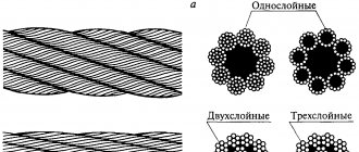
The wire (one element) can have a cross-section of up to 3 mm. This is enough to withstand loads of up to 200 kgf/mm2. Steel cables and ropes differ in terms of lay, which can be single, double or triple. The arrangement of the wire in different layers has one of the following tangents:
- point (usually used for minor intermittent loads);
- linear (used in many areas);
- point-linear (used for additional strength).
Types of steel ropes
Cables are twisted or twisted products made from steel, synthetic and organic threads. In the production of steel products, galvanized high-carbon wire with a cross-section of 0.4–3 mm is used, which has a significant margin of strength under tensile loads (from 130 to 200 kgf/mm2).
The metal threads used in the manufacture of products come in several grades. Wire of category B has the best strength characteristics; raw materials of grades I and II are considered to be of lower quality. Before determining what load a cable of 5 mm or other thickness can withstand, you should take into account that, regardless of the quality of the material, ropes differ in design and come in three types:
- Single lay - made from one strand with wire of the same section. Their elements are twisted around one of the metal threads in up to 4 layers. Steel cables are marked as a sum of numbers indicating the number of wires in the weave. For example, 1+9+9 means that there are 19 wires in the rope, one of which is located in the central part, 9 twists in the first layer and 9 in the second.
- Double lay - made of several strands, applied in 1-2 layers around the core. For the core, twisted wire, organic or mineral materials are used, which improve the strength of the steel cable and prevent strands from falling inside the product. Most often, such products are used for cable work.
- Triple lay - made of several cables. As with double lay, they have a core, but are made from wire of a smaller cross-section and are used where increased flexibility of the ropes is required (usually for cable work).
Wire located in different layers can have a point, linear or point-linear contact. When establishing what load a cable with a diameter of 6 mm or another thickness can withstand, you need to take into account that ropes with point contact (TC) are relevant only for minor pulsating loads. Products with linear touch (LT) have a wide range of applications, while products with point-line touch (PLT) are used in places where LT cannot provide the recommended safety margin.
In the manufacture of products, cross lay is usually used. The wire in its outer layer has a different direction, which guarantees a stronger weave and ease of operation. At the request of customers, manufacturing plants can produce other types of lay, such as single-sided and combined.
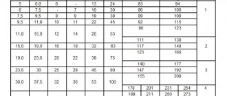
In addition to being classified by design, ropes are classified according to the degree of twist and can be flexible or rigid. The latter are characterized by higher tensile strength, since they are produced from a small number of metal threads of large diameter. To compare the flexibility of certain modifications, you can use the table.
| View | Design | Flexibility factor |
| Single strand | 1x19 | 5 |
| 1x37 | 7 | |
| LK-O | 6x19+1 | 12 |
| TK | 6x19+1 | 15 |
| TLK-O | 6x37+1 | 21 |
| Triple lay | 6x6x7+7 | 27 |
HALF-CYCLE DISCONTINUOUS CHARACTERISTICS
Lecture 10
STRETCH
1. Half-cycle discontinuous characteristics.
2. Half-cycle continuous characteristics.
Textile products most often experience tensile deformation. This type of deformation is the most studied.
The classification of characteristics obtained by stretching the material is presented in the diagram.
Rice. Classification of characteristics obtained by stretching a material
HALF-CYCLE DISCONTINUOUS CHARACTERISTICS
Half-cycle tensile strength properties are used primarily to evaluate the ultimate mechanical capabilities of textile products. By the indicators of mechanical properties obtained when the material is stretched to the point of rupture, the degree of resistance of the material to constantly acting external forces is judged; indicators of breaking load and breaking elongation are important signs of the good quality of the material.
Uniaxial tension. Let us consider the main half-cycle tensile characteristics obtained with simple uniaxial tension.
Indicators of half-cycle characteristics are determined when the material is stretched using tensile testing machines.
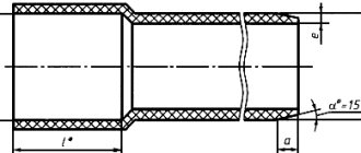
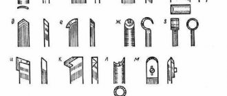
The main shapes of the samples used for simple uniaxial tensile testing and methods of securing them in the clamps of the tensile testing machine are shown in Fig. 1. Fig. 1 Shapes of material samples and methods of securing them in the clamps of a tensile testing machine
A rectangular sample (Fig. 1, a) is accepted as standard for testing fabrics, knitted and non-woven fabrics. A test method based on the use of such a sample is often called the strip method. For fabrics, the following test sample dimensions are established: width - 25 mm, clamping length - 50 mm (in controversial cases, width is 50 mm and clamping length is 200 mm, and for wool - 100 mm). For knitted and non-woven fabrics, the sample width is 50 mm and the clamping length is 100 mm.
Samples, the shape of which is shown in Fig. 1, b and c, are used mainly in research work. To test highly tensile materials (knitted fabrics, films and other materials), samples in the form of a double spatula or in the form of a ring sewn from a strip of material are sometimes used (Fig. 1, d and e). When testing textile materials for simple uniaxial tension, the following main characteristics of mechanical properties are obtained.
Breaking load (р.н.) Рр is the force withstood by test samples of a material when stretched to the point of rupture, expressed in newtons or decanewtons (kilogram-force). It is determined using devices called tensile testing machines. R.n. often called absolute strength.
l yesH=10H = l.02 kgf (kg).
Elongation at break (absolute elongation at break) lр - the increment in the length of the stretched test sample of the product at the moment of its break. Obtain the absolute value of elongation lр , mm, as the difference of the final LK
and the initial
L0
of the sample.
lр= LK - L0
The relative value of elongation of the product at the moment of rupture εр is determined as the ratio lр
to
L0
and are expressed either in fractions of unity
εp =lp·/L0
or as a percentage
ε'p =lp·100/L0
In addition, it is customary to determine elongation at a standard breaking load - the increment in the length of a tensile test sample at the moment of reaching the breaking load provided for by the standards or technical specifications for the product.
With simple uniaxial tension of the test sample, a decrease in its transverse dimensions is observed (Fig. 2). This is typical for many textile products. The dimensions decrease most significantly in the middle of the sample. This property of products is assessed by the coefficient of transverse contraction K ,
which is defined as the ratio of the relative contraction of the sample
εс
to its relative elongation
εр
.
where in
and
b1
is the width of the sample before and after stretching in mm;
L
and
L1
is the length of the sample before and after stretching in mm.
K value
for textile products it ranges from 0.5 to 1.3.
Rice. 2. Change in the shape and size of a product sample under tension
For all textile products, breaking load and breaking elongation are important standard (normative) indicators. Non-compliance of actual breaking load and breaking elongation with state standards or technical specifications is one of the signs of poor quality of the product.
When assessing the mechanical properties of textile materials, it is important to know not only the breaking load and elongation at break, but also the nature of the deformation of the material. A graphical representation of the relationship between load and tensile elongation of materials is given by tensile diagrams (Fig. 3). Such diagrams are recorded using a recording device on a tensile testing machine.
Rice. 3. Load - elongation diagrams (odd numbers indicate the elongation curves of materials along the warp (length), even numbers - along the weft (width):
1—2
-Cotton fabric;
3-4
- linen;
5—6 cotton
and wool fabric;
7-8
- knitted cotton (smooth) fabric;
9-10
- non-woven cotton - canvas stitched fabric
As can be seen from the figure, textile materials of the main types are characterized by a significant increase in elongation with a slight increase in the effective load. This is especially pronounced in knitted and non-woven fabrics, and to a lesser extent in fabrics, which is mainly explained by the structural features.
Relative characteristics are also used to assess the strength properties of textile products.
The relative breaking load P0, daN km/kg (kgf km/kg), is determined by the ratio of the breaking load per 1 mm of the width of the test sample of the material to the mass of 1 m2 of this material.
where t -
weight of 1 m2 of material, kg;
b —
width of the working part of the test sample, mm.
The relative breaking load indicator, which takes into account the mass of the material, allows you to evaluate materials of different masses.
An important characteristic of the strength properties of textile materials is the specific (calculated) breaking load Ru -
breaking load per element of the material structure (per one warp or weft thread in fabric, one loop row or column in knitwear, one line of stitching in non-woven fabrics).
where Рр -
breaking load, daN (kgf);
T -
linear density of a material - the number of threads in fabric, rows or columns in knitwear, stitching lines in non-woven fabric along which a sample of the material being tested is broken.
Using indicators of breaking load and density of the substance (threads), you can calculate the value of breaking stress σр , Pa (N/m2) (mechanical stress) using the formula:
where ρ
— density (volumetric mass) of the substance (threads), kg/m3.
When stretching samples, a certain amount of work is expended, which is spent on overcoming the energy of bonds acting in the material (between fibers and threads, between macromolecules in the fiber structure).
The work of rupture shows how much energy is expended to overcome the bonding energy between the particles of the material and bring it to complete destruction. The rupture work Rp
geometric area limited by the discontinuity curve and maximum coordinates
Pр
and
lр. The absolute work expended on breaking the sample can be calculated using the formula Rр , (kgf cm; J):
where η
is the coefficient of completeness of the tensile diagram, determined by the ratio of the area limited by the tensile curve to the entire rectangular area of the diagram, limited by the sides
Рр
and
lр
, from which:
The larger the value of η,
the higher the amount of work done by the material at rupture.
The value of the coefficient η
for different textile materials is different and is: for fabrics 0.25–0.75; for knitted fabrics 0.15-0.4; for non-woven (glued) fabrics 0.5-0.8.
For materials of different masses, it is customary to calculate the specific work of rupture rm
,
J, according to the formula:
where t
— mass of 1 m2 of material, g.
Uniaxial tearing. When using clothing, camping tents, covers and other products made from fabrics, the fabrics in areas of pockets, valves, etc. experience mechanical stress . This stress is concentrated on a small area of the fabric, on a group or even a single thread, causing tissue failure. Tear strength is characterized by the tearing load Рtear — the force (kgf, daN) required to tear a specially cut test strip of fabric. This load characterizes the ability of fabrics to withstand force, which is concentrated in a relatively small area, for example, during tears, when rigidly securing the edge of the fabric, etc. There are various methods for testing fabrics for tearing. G.N. Kukin and E.F. Fedorova classify tear test methods into two groups.
The methods of the first group are characterized by the fact that when testing test samples (strips), the threads located perpendicular to the direction of the applied load break.
The methods of the second group differ in that when testing test samples, the threads located along the direction of the applied load are broken.
The structure of the material has a significant impact on the tearing load. The tearing load indicators largely depend on the tissue compaction coefficient: the lower the coefficient, the higher the tearing load. The fill factor of the fabric also significantly affects the tearing load. For fabrics made from polyester and viscose threads, the optimal value of the tearing load is observed at a filling factor of 0.7-0.8.
The absolute value of the tearing load Рdisd is determined by the formula
where Rn. T
— breaking load for the thread in the fabric.
Biaxial and multiaxial tension. During the manufacture of garments (especially when molding parts), as well as during the operation of clothing, parachutes, umbrellas, sails and other products, the material from which they are made is subjected to tension simultaneously in different directions as a result of the applied loads. At the same time, the stresses and deformations developing in the material, as a rule, are not the same in different directions and depend mainly on the structure and properties of the material, as well as on the type and size of the product, the nature of the work performed and other factors. The study of the behavior of textile materials under biaxial and multiaxial tension is of increasing interest, and the results of these studies are used in the development of new materials, design of garments, and assessment of their quality.
The testing methods currently used are divided into two groups: the first is biaxial tensile methods and the second is multiaxial tensile methods.
Biaxial tension is the simultaneous deformation of a material in two mutually perpendicular directions.
The material receives multiaxial tension mainly under the action of a load applied perpendicular to the plane of the sample. The material experiences this type of load when it is pressed through by a ball or membrane.
Breaking load. What does it mean?
An incredibly frequently asked question. Breaking load is a characteristic that is indicated on leader materials, fishing lines, leadcore and shock leaders. On the one hand, it means what load a particular material can withstand. But for many anglers, any weight value causes a strong association with the weight of the fish that can be caught with this material.
Right off the bat
The breaking load has nothing to do with the weight of the fish caught. If the monofilament says that it can withstand 5.63 kg, this only means that at the limit of its elongation (if we tie the line to the ceiling) it will withstand a weight of 5.63 kg. But 6kg probably won’t hold up.
Can we say that when fishing, the carp reaches the stretch limit of the fishing line? Probably yes, when we tighten the clutch and use an iron pipe instead of a rod...
Remember that you have the following main points for leveling fish jerks:
- A rod that bends and dampens sudden jerks of fish
- A friction clutch that releases the fishing line and dampens prolonged jerks of the fish
- The fisherman, that is, you, who can move along the shore, isn’t it?
- Water. Water resistance and air resistance are completely different things. Try waving your hand in the air and underwater - the difference is colossal.
The four factors listed above so reduce the final force that the fish exerts on the fishing line that this 5.63 kg breaking load, even in the least skilled hands, will turn into the entire 25.63 kg.
To prevent you from getting a break, you need to follow the following simple rules for each point:
- Hold the rod in one hand if possible. So that your brush touches the form and that’s it. With a sharp jerk, the rod will always play back. If you rest the butt on your thigh, only the upper half of the form will work, and not the entire form. This is especially true at short distances, when the fish is near the shore.
- Adjust the clutch so that when fishing it makes a slight cracking noise. That is, the fish will go at a stretch, but with a sharp jerk the line will be pulled off. Your task is to control the friction so that the fish gets tired, but does not have the opportunity to achieve the effect when the line becomes a stake and actually breaks.
- Try not to fall out of reality. If the shore allows, always stay opposite the fish. Move around. You must always meet the fish face to face. And don't give up. The line should be in tension, running off the reel in time after the fish. This way your trophy will get tired faster, being held in tension.
- Don't try to raise the fish ahead of time and take your time. This is not a bream that took a breath of air and immediately gave up. Carp or cupid are more serious rivals. Take your time and enjoy the bite.
Where it is thin there it breaks
In float fishing, there really is a rule when the leader is selected from a material that is 0.02 thinner than the main line. For example, if the main line is 0.16, then the leash is no thicker than 0.14. Millimeters, of course. This is done so that when it breaks, it is the leash that breaks.
Carp fishing has a slightly different approach. You don't have a tour that lasts 4-5 hours. Your gear is at such a critical minimum that you simply need to make a “weak point” in order to know exactly where the break will be. You don’t have time to carry out repairs and so on. And the proximity to the shore does not allow you to use a large supply of gear, otherwise the cautious fish will not bite at all.
In carp fishing, when fishing at great depths, or far from the shore, taking into account the weight of the fish and size, delicacy is calculated in completely different categories. By the standards of float fishing, carp tackle is the same as a submarine in the Bolshoi Theater.
Breaking loads used by our team
- Sport - line 0.26mm, shock - 0.28mm, leader material - 20lb
- Regular fishing - line 0.30mm, shock - 0.28mm, leader material - 25lb
The difference between sport and regular fishing is the casting distance. Therefore we decrease. If it were our will, we would generally fish 0.40mm from under the shore.
What do you think about this? Write in the comments!
Full or partial copying without the consent of the portal editors is prohibited