Increased originality
Test questions 1. Explain the essence of the phenomenon of viscous friction. What is the nature of the internal friction forces of a fluid? Viscosity or internal friction is the property of fluid bodies (liquids and gases) to resist the movement of one part relative to another. This phenomenon determines the dissipation (absorption) of energy during deformation of the medium. During shear deformation, the viscosity is called shear viscosity. When the volume is deformed (universal compression), bulk viscosity appears. In this case, we will only touch upon the issue of shear viscosity. The essence of the phenomenon is that moving layers of gas or liquid entrain neighboring layers and, conversely, stationary layers (or moving at a lower speed) slow down faster neighboring layers. Thus, internal friction forces (or viscous forces) act between any adjacent layers of the medium under consideration. The mechanism by which these forces arise is the transfer of momentum (amount of motion) from one layer to another.2. What is the coefficient of dynamic viscosity? In what units is viscosity measured in the SI system?
The coefficient of dynamic viscosity is a value numerically equal to the force of internal friction with which one layer drags or slows down another layer of liquid, provided that the contact area of the layers and the velocity gradient . In the SI system, the unit of dynamic viscosity is taken to be the viscosity of a medium in which one layer drags or inhibits another with a force of , if the contact area of the layers and the velocity gradient are .
3. What forces act on a body moving in a liquid?
A body immersed in a liquid and remaining in equilibrium afloat is acted upon by two forces: the force of gravity and the buoyant force equal to it (and equal to the weight of the liquid displaced by the immersed volume of the body). Three forces act on a body immersed in a liquid and sinking: the force of gravity, which is unequal to it (less), the buoyancy force (equal to the weight of the liquid displaced by the immersed volume of the body), as well as the frictional force during movement, which largely depends on the speed of immersion and the viscosity of the liquid . A body immersed in a liquid and lying tightly at the bottom is acted upon by three forces: the force of gravity, the unequal buoyant force, and the reaction force from the bottom. In this case, the buoyant force decreases by an amount equal to the weight of the liquid occupied by that part of the body volume under which there is no water
4. Define laminar and turbulent fluid flow.
Turbulent flow is a fluid flow in which its particles perform unsteady and disordered movements along complex trajectories, leading to mixing of layers. Laminar is an ordered flow of fluid in which the trajectories of motion of neighboring particles differ little from each other.
5. Write down the Stokes formula and indicate the conditions for its applicability.
For spherical bodies, the modulus of the viscous friction force is determined by the Stokes formula (1) where r is the radius of the ball; V is the speed of its movement relative to the liquid. It is important to note that formula (1) is valid only in the case of laminar fluid flow relative to the ball (the speed of the ball should be small), and the fluid extends infinitely in all directions, i.e. The dimensions of the vessel in which the liquid is located must be much larger compared to the dimensions of the ball.
6. Determine the magnitude of the friction force acting on a steel ball with a diameter of 3 mm falling at a speed of 0.75 m/s in a liquid with a viscosity coefficient of 1.5 Pa.s. F=6*3.14*1.5*0.003*0.75=0.063
7. Why does the ball accelerate at the beginning of its movement and then move uniformly? What is a velocity gradient? At the beginning of the ball's movement, the movement will be accelerated due to the acceleration of gravity. As the speed increases, the resistance force also increases, and the acceleration of the ball decreases. There comes a moment when the forces acting on the ball are balanced, the acceleration becomes zero, and the movement of the ball becomes uniform in section L. The velocity gradient is the change in the speed of two layers of liquid dV at the distance between the layers dX.
8. Write down the working formula, explain the conditions for its use and the reason for starting to measure time not from the surface of the liquid.
The upper mark is placed several centimeters below the upper level of the liquid to ensure uniform movement of the ball in the liquid. 9. List the main sources of measurement errors carried out in this work.
Lathes
FEDERAL AGENCY FOR EDUCATION
Branch of the State educational institution of higher professional education
KRASNOYARSK STATE PEDAGOGICAL UNIVERSITY
them. V.P. Astafiev in Zheleznogorsk
Faculty of Informatics and Technology
Specialty 050502 “Technology and Entrepreneurship”
Abstract on the topic:
"Lathes"
- Completed by: 3rd year student
- Larioshkin Dmitry Nikolaevich
- Checked: _______________________
- __________________________________
ZHELEZNOGORSK
2012
Content
History of the lathe ___________________________________________________ 3
General information _________________________________________________________________ 7
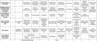
- Types of lathes ___________________________________________________ 8
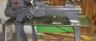
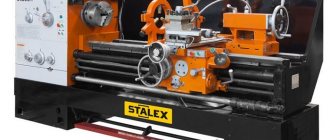
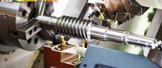
- Screw-cutting lathe _________________________________________________ 8
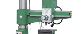
- Vertical lathe _________________________________________________ 8
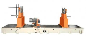
- Lobe lathe _________________________________________________ 9
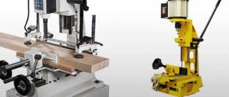
- Turret lathe __________________________________________ 9
- Automatic longitudinal turning ________________________________________________ 9
- Multi-spindle automatic lathe ___________________________________ 10
- Safety precautions when working on a lathe _________________________________ 14
- Cutting tools ___________________________________________________ 15
- Machining parts on lathes__________________________________________ 16
- Machining of cylindrical and end surfaces________________________ 17
- Drilling and boring holes _________________________________________________ 18
- Machining of tapered holes ________________________________________________ 19
- Thread cutting on lathes _____________________________________20
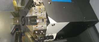
- Familiarization with the operation of CNC machines_____________________________________________ 22
- Literature ________________________________________________________________ 23
History of the lathe
History dates the invention of the lathe to 650. BC e. The machine consisted of two established centers, between which a workpiece made of wood, bone or horn was clamped. A slave or apprentice rotated the workpiece (one or more turns in one direction, then in the other). The master held the cutter in his hands and, pressing it in the right place against the workpiece, removed the chips, giving the workpiece the required shape.
Later, a bow with a loosely stretched (sagging) bowstring was used to set the workpiece in motion. The string was wrapped around the cylindrical part of the workpiece so that it formed a loop around the workpiece. When the bow moved in one direction or the other, similar to the movement of a saw when sawing a log, the workpiece made several revolutions around its axis, first in one direction and then in the other.
In the 14th and 15th centuries, foot-powered lathes were common. The foot drive consisted of an ochep - an elastic pole, cantilevered above the machine. A string was attached to the end of the pole, which was wrapped one turn around the workpiece and attached to the pedal with its lower end. When you press the pedal, the string is stretched, forcing the workpiece to make one or two turns, and the pole to bend. When the pedal was released, the pole straightened, pulled the string up, and the workpiece made the same revolutions in the other direction.
Around 1430, instead of the ochep, they began to use a mechanism that included a pedal, a connecting rod and a crank, thus obtaining a drive similar to the foot drive of a sewing machine, which was common in the 20th century. From that time on, the workpiece on the lathe received, instead of an oscillatory movement, rotation in one direction throughout the entire turning process.
In 1500, the lathe already had steel centers and a steady rest, which could be strengthened anywhere between the centers.
On such machines, quite complex parts were processed, which were bodies of rotation, right down to the ball. But the drive of the machines that existed at that time was too low-power for metal processing, and the forces of the hand holding the cutter were insufficient to remove large chips from the workpiece.
As a result, metal processing turned out to be ineffective. It was necessary to replace the worker's hand with a special mechanism, and the muscular force driving the machine with a more powerful engine.
The advent of the water wheel led to an increase in labor productivity, while having a powerful revolutionary effect on the development of technology. And from the middle of the 14th century. water drives began to spread in metalworking.
In the mid-16th century, Jacques Besson invented a lathe for cutting cylindrical and conical screws.
In the 17th century lathes appeared, in which the workpiece was no longer driven by the muscular power of the turner, but with the help of a water wheel, but the cutter, as before, was held in the hand of the turner. At the beginning of the 18th century. lathes were increasingly used for cutting metals rather than wood, and therefore the problem of rigidly fastening the cutter and moving it along the table surface being processed was very relevant. And for the first time, the problem of a self-propelled support was successfully solved in the copying machine of A.K. Nartov in 1712. He invents an original turning-copying and screw-cutting machine with a mechanized support and a set of replaceable gears.
The inventors took a long time to come to the idea of mechanized movement of the cutter. For the first time, this problem became especially acute when solving such technical problems as thread cutting, applying complex patterns to luxury goods, making gears, etc. To obtain a thread on a shaft, for example, markings were first made, for which a paper tape of the required width was wound onto the shaft, along the edges of which the outline of the future thread was applied. After marking, the threads were filed by hand. Not to mention the labor intensity of such a process, it is very difficult to obtain satisfactory quality of carving in this way.
And Nartov not only solved the problem of mechanizing this operation, but in 1718-1729. I improved the scheme myself. The copying finger and support were driven by the same lead screw, but with different cutting pitches under the cutter and under the copier. Thus, automatic movement of the support along the axis of the workpiece was ensured. True, there was no cross-feed yet; instead, the swing of the “copier-workpiece” system was introduced. Therefore, work on the creation of the caliper continued.
A more advanced design of the support, close to the modern one, was created by the English machine tool builder Maudsley, but A.K. Nartov remains the first to find a way to solve this problem.
Second half of the 18th century. in the machine tool industry was marked by a sharp increase in the scope of application of metal-cutting machines and the search for a satisfactory design for a universal lathe that could be used for various purposes.
In 1751, J. Vaucanson in France built a machine, which, in its technical data, already resembled a universal one. It was made of metal, had a powerful frame, two metal centers, two V-shaped guides, and a copper support that ensured mechanized movement of the tool in the longitudinal and transverse directions. At the same time, this machine did not have a system for clamping the workpiece in a chuck, although this device existed in other machine designs. Here provision was made for securing the workpiece only in the centers. The distance between centers could be changed within 10 cm. Therefore, only parts of approximately the same length could be processed on the machine.
In 1778, the Englishman Ramedon developed two types of thread cutting machines. In one machine, a diamond cutting tool moved along parallel guides along a rotating workpiece, the speed of which was set by the rotation of a reference screw. Replaceable gears made it possible to obtain threads with different pitches. The second machine made it possible to produce threads with different pitches on parts longer than the length of the standard. The cutter moved along the workpiece using a string wound onto the central key.
In 1795, the French mechanic Senault made a specialized lathe for cutting screws. The designer provided replaceable gears, a large lead screw, and a simple mechanized caliper. The machine was devoid of any decorations with which the craftsmen previously loved to decorate their products.
The accumulated experience made it possible by the end of the 18th century to create a universal lathe, which became the basis of mechanical engineering. Its author was Henry Maudsley. In 1794, he created a caliper design, which was rather imperfect. In 1798, having founded his own workshop for the production of machine tools, he significantly improved the support, which made it possible to create a version of a universal lathe.
In 1800, Maudsley improved this machine, and then created a third version, which contained all the elements that screw-cutting lathes have today. It is significant that Maudsley understood the need to unify certain types of parts and was the first to introduce standardization of threads on screws and nuts. He began producing sets of taps and dies for cutting threads.
One of Maudsley's students and successors was R. Roberts. He improved the lathe by placing the lead screw in front of the bed, adding gearing, and moving the control handles to the front panel of the machine, which made operating the machine more convenient. This machine operated until 1909.
Another former Maudsley employee, D. Clement, created a lobe lathe for processing large-diameter parts. He took into account that at a constant speed of rotation of the part and a constant feed speed, as the cutter moves from the periphery to the center, the cutting speed will fall, and he created a system for increasing the speed.
In 1835, D. Whitworth invented an automatic feed in the transverse direction, which was connected to a longitudinal feed mechanism. This completed the fundamental improvement of turning equipment.
The next stage is the automation of lathes. Here the palm belonged to the Americans. In the USA, the development of metal processing technology began later than in Europe. American machine tools of the first half of the 19th century. significantly inferior to Maudsley machines.
In the second half of the 19th century. The quality of American machines was already quite high. The machines were mass-produced, and full interchangeability of parts and blocks produced by one company was introduced. If a part broke, it was enough to order a similar one from the factory and replace the broken part with a whole one without any adjustment.
In the second half of the 19th century. elements were introduced that ensure complete mechanization of processing - an automatic feed unit in both coordinates, a perfect system for fastening the cutter and the part. Cutting and feed modes changed quickly and without significant effort. The lathes had elements of automation - automatic stop of the machine when a certain size was reached, a system for automatically controlling the speed of frontal turning, etc.