A pulley block is a special device for lifting loads, consisting of two or more blocks that are sequentially wrapped around a rope or chain. The pulley design can be designed to gain in lifting speed or force. The Lenstal online store presents a large selection of blocks and ready-made multi-block systems of various parameters. You can buy a chain hoist from us with delivery throughout St. Petersburg and the region, as well as to the regions of Russia.
Initially, the pulley system arose to ensure the lifting and movement of cargo. It is from the advent of the device that the era of development of lifting mechanisms can be counted. Later, the device became widespread in various fields - from sailing rigging to arranging crossings for climbers.
Purpose and use of the chain hoist
Lifting mechanisms are designed using the rule of leverage and friction to increase the force or speed of lifting an object. Two key elements of the pulley design form the basis for the operation of this mechanism:
- A fixed pulley is an element that is attached to machinery or another strong static element. It performs the function of distributing pressure between structural elements.
- The movable pulley, connecting to the load using an equipped hook, must withstand the maximum possible pressure and maintain the functionality of the mechanism.
Cables connect structural elements. The fixed pulley consists of rollers, each of which carries a chain or rope, which allows reducing the pressure on each roller by increasing the number of working branches, thus, to lift a heavy load, you need to calculate and organize a suitable number of rollers.
- The chain hoist on a crane is used with enhanced strength characteristics; it is also used on rigging devices and on small vessels. Suspended structures in which suspended power lines are tensioned, machines, crossings, railings, lifting structures in sports have been practicing the use of chain hoists for many years to facilitate work.
- Pulley hoists with enhanced speed characteristics are used in hydraulic and pneumatic lifting systems.
- When it is necessary to lift or lower heavy objects, a mechanism is needed that is capable of maintaining constant pressure on the supports of overhead, gantry and jib cranes; a dual lifting mechanism is actively used.
One of the main characteristics of such a mechanism is considered to be its multiplicity. This characteristic of this device is calculated as follows:
- the speed at which the moving branch of the mechanism moves ÷ the speed at which the load is lifted;
- the number of rope branches with a suspended load ÷ the number of rope branches attached to the drum.
With such a calculation, we determine we can determine the coefficient of the gained force or speed based on the result of using this mechanism. You can change the multiplicity of the pulley by adding or removing additional pulleys of the system, observing the following conditions:
- If the total number of additional pulleys is odd, they must be attached to the end of the cable on a stationary pulley.
- If the total number of additional pulleys is an even number, they must be attached to the end of the cable on the hook clip.
Pull on the lower block (horizontal pull)
Why on the list:
It’s not for nothing that the lat pulldown is considered one of the main exercises for back training. Multi-joint exercises like this recruit more muscle groups and allow you to lift more weight. Unlike single-joint movements, they signal the body that it is time to increase the secretion of growth hormone and testosterone, which equates to more efficient muscle development. In addition, in this exercise you can use different grip options - narrow, wide, forward and reverse, which makes it possible to work a muscle group in many different ways in one exercise.
During training:
Place horizontal rows towards the end of your back workout. The first half of the training session should consist of deadlifts, bent-over rows and/or T-bar rows, and then you can move on to exercises on cable machines. To increase your range of motion, try doing lat pulldowns with one arm.
Device
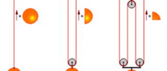
Thus, we see a diagram of the simplest pulley device:
The drive drum is depicted using a large circle, small circles indicate the system pulleys. The diagram shows two types of cable/chain reeving:
- The pulley diagram on the left shows the fixation of one end of the rope/chain on a stationary pulley, and the second on the drive drum.
- The diagram on the right shows the fixation of the cable/chain on the traction mechanism, as well as on the axis of the moving element.
More advanced pulley systems consist of three or more moving and stationary parts that are tightened by rope in a specific sequence. A complicated chain hoist diagram looks like this:
The pulley operates using two fixed pulleys that are fixed to the surface, and two that are movable. Two of its pulleys are fixedly fixed to the surface, the others move. Such a scheme approximately quadruples the pressure exerted on the drive when pulling the cable. The accuracy of this difference is approximately 93-97%, varying depending on the quality of the elements used and the accuracy of the design solutions.
If you need to determine the exact efficiency of a chain hoist or calculate the lifting scheme of a complex mechanism, you need to turn to exact formulas. In addition, it is impossible to do without them due to the fact that it is almost impossible to create ideal conditions in everyday life and because the structure is also affected by the friction force that is created when the pulleys move along the rope/chain during the rotation of the roller, regardless of the bearings used . Negative factors additionally include the lack of flexible and pliable rope on the construction site and in construction equipment. The rigidity of steel cables and chains forces additional effort to move the load, which is also important to consider.
There is an equation for moments of force for pulley hoists:
The elements of the formula are deciphered in this way:
- Sc – the force of movement of the running rope/chain.
- Sn is the force of movement of the oncoming rope/chain.
- q*Sн – the force that must be applied to bend or unbend a rope/chain, taking into account the rigidity of this rope equal to q.
- N*f – friction force, taking into account the friction coefficient in the block equal to f.
If it is necessary to determine the moment, all forces must be multiplied by the arm, which is equal to the radius of the pulley R. The force with which the rope/chain runs up and down is formed when the threads of the rope/chain begin to interact and create friction. Considering the fact that the force that needs to be applied to bend or straighten the rope/chain is lower than those listed above, the calculation of the impact on the block axis is regularly neglected: This equation is deciphered as follows: N is the level of impact on the block axis. Sн – the force of movement of the oncoming rope/chain (you can use the value taken approximately equal to Sс). sin(a) – degree of angle. with which the rope/chain is deflected from the axis.
Next we get the formula for calculating the efficiency of the pulley block:
Calculation of the chain hoist
Calculation operations to determine the forces acting on the elements of the system during operation must begin with determining the parameters and forces acting on the block:
- load impact force (Sн);
- motor traction force (Sc);
- α – deflection angle;
- D – block (stream) diameter;
- d – bushing diameter.
It is worth immediately noting that modern devices of this type actually do not have deflection angles. Therefore (due to the lack of practical meaning) they can be neglected, and in further calculations the sine of this angle can be taken as unity.
For a block, the torque equation looks like this:
Sc*R = Sn*R + q*Sn*R + N*f*d/2
- SнR is the moment of force with which the load acts on the system;
- q is a coefficient that determines the rigidity of the cable when bending around the roller (determined experimentally), it takes into account the forces caused by the structure of the turns of the cable or rope itself;
- N – load on the block axis;
- f – coefficient that determines the friction force of the block bushing.
For real practical calculations, the q indicator does not matter. More precisely, its indicator is so small in comparison with the friction force in the bushing that it can be ignored. In this case, the formula looks like this:
Sc*R = Sn*R + N*f*d/2
Find the load N. It is determined by the difference in loads on the cable from different sides of the block:
N = 2*Sн*R*sin(α)
And since we are omitting angles, we simplify the formula to:
N = 2*Sn*R
Combining everything, we get the formula for determining the efficiency of a lifting device:
Removing minor parameters, the formula simplifies to:
ηп = 1/(1+2*f*d/D)
This formula shows that for the efficiency of a system, the most important thing is the quality of the blocks and their materials used in it. The lower their friction force, the higher the efficiency index.
As a rule, the following levels of efficiency of the block system are used in calculations:
- 97% is the accepted average if the elements use bronze bushings and rolling bearings;
- 95% – plain bearings are used;
- 93% and below – dusty places, aggressive natural operating conditions of the mechanism, high temperature.
Now the calculation of forces per block must be applied to the corresponding number of them in the system.
S1 = S0* ηп
S2 = S1*ηп = S0* ηп * ηп = S0*( ηп)2
Sn = S0*( ηп)n
The sum of efforts with the geometric progression conversion formula will allow you to obtain the indicator S0 in direct dependence on the weight of the load being lifted (P).
S0 = P*(1 — ηп)/(1 — (ηп)n+1
In addition, depending on the design of the system, it will probably be necessary to take into account the loads on the remaining deflection rollers, the operating efficiency of which should also be taken into account when calculating.
The principle of operation of the chain hoist
A rope/chain is thrown through a static pulley to lift the load; the load is lifted by applying forces comparable to the original weight. A chain is passed through this structure. The height to which the load is lifted must be equal to the length of the rope. This scheme does not allow reducing either the power or speed indicators of the process of moving cargo.
It is possible to halve the effort required when using a lifting mechanism; the end of the rope fixes the system on a static pulley, and a special movable roller and hook are suspended from the load. In this case, the movable pulley of the mechanism moves parallel to the load and the effort required to lift it is reduced. The operation of such a lifting device is based on these simple manipulations.
The main task of fixed blocks is to create a path for the rope/rope to move, preventing the effort required from being reduced. Movable pulleys, when attached to a load, can benefit from effort. You can halve the effort required to lift a load by increasing the composition of the design system into paired pulleys, consisting of a movable and a static pulley, based on the number of movable rollers.
Types of pulleys
All chain hoists can be divided into two categories:
- power;
- high-speed.
Based on the name, the purpose of each type is determined. The first is the most common and is used for lifting loads, exactly as it was invented. The high-speed option is a modified design where great efforts are aimed at increasing the speed of transportation. This principle is used to create cable cars at ski resorts.
In addition, the difference lies in the number of rollers and working branches, as well as other modifications. An electric drive and a stopper can be connected to the structure. Another difference lies in the material of the rope, because it can be presented in the form:
- ropes;
- metal rope;
- iron chain;
- electrical cable.
In construction equipment, the second option is most often used due to the strength of the material. Rope ropes are most often used in tourism, rescue operations and so on. The use of an iron chain can be found very rarely; these are narrowly targeted varieties for certain jobs.
Types of pulleys
Power mechanisms are systems that allow saving effort on lifting or moving a load by reducing the speed of lifting or moving it, thus, the saved effort is inversely proportional to the speed expended. There are also high-speed mechanisms, the lever in such systems is a rope, but the efforts are directed to the speed of lifting the load, which is very important for hydraulic systems. There are the following types of pulleys:
- Single power pulleys, in such systems the load must be suspended from a moving block, and the working branches take on the traction forces. When using power systems, it is necessary to take into account the need for the drum to have a cut in one direction, since one end of the edge/chain will be attached to it, and the other to a fixed block or hook cage.
- High-speed pulleys, in such systems the load must be suspended at the end of the working branch, and the forces are applied to the moving block.
- Double power pulleys, in such systems the load of both ends of the rope/chain is attached to a drum with a thread in both directions. The leveling upper block equalizes the length of the rope branches if they are unevenly extended.
Rules for chain hoists
Each manual pulley operates on the basis of the laws of physics, and therefore its operation complies with several fairly simple rules that it is advisable to familiarize yourself with.
- Rule number one. The gain in effort is provided exclusively by moving blocks or rollers, which are attached to the load or to the rope coming from the load. Stationary blocks never provide a gain in strength.
- Rule number two. A win in strength is a multiple of a loss in distance. In other words, for example, a double pulley assembly for each meter of lifting an object requires pulling two meters of rope through its entire system. At the same time, a 6:1 chain hoist requires you to pull out 6 meters of cable to move the load upward by one meter. Let’s summarize: the greater the “strength” of the pulley, the slower (by the same amount) the load will rise.
The complex chain hoist deserves special attention. By itself, it is a collection of simple pulley hoists, each of which pulls the other. In this way, several pulleys can be mounted together. This type is most often used during rescue operations.
In conclusion, it would be correct to say the following: the pulley system (the principle of its operation is quite easy to understand upon careful study of the issue) was, remains and, most likely, will be a faithful assistant to a person for a very long time in solving many pressing issues related to construction, installation, loading, unloading and other operations that are quite labor-intensive. The main problem, the complete elimination of which is not possible today due to, again, ideally working physical laws, is the presence of friction force in the system.
What affects the efficiency of a lift?
In the previous sections of the article, the approximate multiplicity of pulleys was mentioned. which is rounded up. However, in actual use of the mechanism, it often turns out to be lower than indicated. What factors influence the lift and its effectiveness?
You need to pay attention to the following issues:
- How many blocks were used?
- What material is the rope/rope made of?
- What type of bearings were used?
- Were all the elements of the chain hoist properly lubricated?
- Was the rope used the correct diameter and length?
- What was the degree of angle between the rope and the plane of the roller?
Geometric parameters of the drum and pulley blocks
| (5.15) |
Figure 5.9 shows the design diagram of the drum for a double chain hoist (the natural appearance of this drum is shown in Figure 5.2).
Figure 5.9 – Design diagram of the double pulley pulley drum
The drum consists of two threaded sections 1, as well as two outer sections 2. In the middle part of the drum there is a non-rifled section 3.
Total drum length
| (5.16) |
Taking into account expressions (5.12), (5.13), (5.14), as well as recommended values l 1 = (3...4) pt; l 0 = 2 pt, z 1= 1.5…2 turns, drum length is determined by the expression
| (5.17) |
The length of the non-threaded section can previously be taken equal to 150...200 mm or determined by the expression
| (5.18) |
where B3 is the distance between the axes of the external blocks of the hook suspension (accepted according to table A.5); hmin is the minimum distance between the axis of the drum and the axis of the hook cage blocks (hmin ≈ 3D1 can be assumed in advance); α is the maximum permissible angle of deviation of the ropes from the normal to the drum axis; α ≤ 6º is accepted.
The drum wall thickness δ is determined from the compressive strength condition and from the technological manufacturing conditions.
The torsional and bending stresses in the drum wall are insignificant compared to the compression stress, so they are taken into account only when the ratio of the drum length to its diameter is more than 3...4.
Drum wall thickness based on compressive strength
| (5.19) |
where [σcom] is the permissible compressive stress for the drum material (accepted according to Table 5.7).
Table 5.7 – Permissible stresses [σcompressor] of the wall material
drum
| Drum material | Allowable stresses [σcompressor], MPa | ||
| Mechanism operating mode group | |||
| M1…M5 (1M…3M) | M6, M7 (4M, 5M) | M8 | |
| Steel | |||
| VSt3sp | 150 | 130 | 110 |
| steel 20 | 160 | 140 | 120 |
| 09G2S | 195 | 165 | 140 |
| steel 35L | 170 | 140 | 120 |
| steel 55L | 200 | 165 | 140 |
| Cast iron | |||
| SCH15 | 90 | — | — |
| SCH18 | 100 | 90 | — |
| SCH24 | 130 | 115 | 100 |
According to the technological conditions of drum manufacturing associated with the peculiarities of foundry production, the wall thickness is:
cast iron drum
| (5.20) |
and steel drum
| (5.21) |
From the obtained values of δ, δ' and δ" the larger value is taken, rounded up to the nearest whole number.
5.4 Example of completing a task
Perform calculations and selection of pulley elements for a jib-gantry crane.
Initial data: crane type – cantilever-gantry; load capacity – Q = 12.5 t; load lifting speed – v gr = 0.25 m/s; lifting height – H = 10 m; operating mode group according to ISO 4301/1 – M6.
According to the stated recommendations for a crane of this type, we accept: the rope reeving diagram for a cantilever gantry crane, shown in Figures 5.3 and 5.10; chain hoist type – double, a = 2; pulley multiplicity – up = 2; Efficiency of the pulley block – ηп = 0.99 (Table 5.3); number of guide blocks – n = 6.
Figure 5.10 – Rope reeving diagram
Solution
a) selection of rope and load-handling device
Using expression (5.4), we determine the maximum force in the traction branch of the rope when lifting the load
where FQ is the gravity force of the load and the hook suspension, determined by formula (5.5)
ηо – overall efficiency of the pulley and bypass blocks, determined by formula (5.6)
where ηp = 0.99 is the efficiency of the pulley block at u p = 2 (Table 5.3); ηb = 0.98 – block efficiency when installed on rolling bearings and normal lubrication (Table 5.2); n = 6 – number of guide (bypass) blocks in the rope reeving scheme.
The calculated breaking force of the rope is found by expression (5.7)
where zp = 5.6 is the coefficient of rope utilization in the M6 mode (Table 5.4).
In Table A.1, we select, according to GOST 2688-80, a double lay rope of type LK-R, design 61×9+1 o.s. with a diameter d = 21 mm, having a minimum breaking force F0 = 222 kN with a marking group of wires σв = 1568 MPa.
We determine by expression (5.8) the actual utilization factor (safety factor) of the rope
A rope with a diameter of 21 mm, cargo (G), first grade (I), made of uncoated wire (-), non-unwinding (N) is designated as:
Kanat-21-G-N-1568 GOST 2688-80.
Based on the specified load capacity Q = 12.5 t and operating mode group M6, we select hook blank No. 17 from Table A.4.
b) determination of block diameters and drum sizes.
The minimum diameters at the center of the wound rope are found using expressions (5.9) taking into account the operating mode group M6 (Table 5.5):
drum
take D 1 = 500 mm;
chain hoist blocks
take D 2 = 500 mm;
equalization block
we take D 3 = 400 mm.
The pitch of winding the rope onto the drum at dк = 21 mm is taken according to table 5.6 - pt = 24 mm.
The total length of the drum for a double chain hoist is determined by expression (5.17)
where b = 150...180 mm is the width of the non-threaded section of the drum.
We accept l b = 1150 mm.
The thickness of the drum wall from the compressive strength condition is determined by expression (5.19)
where [σcom] = 90 MPa for the drum material SCh18 cast iron and operating mode group M6 (Table 5.7).
Using expression (5.20), we specify the wall thickness of the cast iron drum according to the technological manufacturing conditions
We finally accept the drum wall thickness δ = 17 mm.
5.5 Test tasks
1. Study theoretical material.
2. Provide a brief description of the purpose, design and operating principle of crane lifting mechanisms.
3. From Table 5.8, select the initial data for calculating the crane elements in accordance with your personal option.
Table 5.8 – Initial data
| Options | Option** | ||||||||
| 1 | 2 | 3 | 4 | 5 | 6 | 7 | 8 | 9 | |
| Crane type* | I | II | III | IV | I | II | III | IV | I |
| Load capacity, t | 2 | 8 | 10 | 12,5 | 3,6 | 25 | 12 | 20 | 1,6 |
| Load lifting speed, m/s | 0,32 | 0,27 | 0,2 | 0,32 | 0,25 | 0,16 | 0,25 | 0,32 | 0,27 |
| Load lifting height, m | 8 | 10 | 12 | 14 | 10 | 8 | 14 | 12 | 9 |
| Mechanism operating mode | M4 | M5 | M6 | M7 | M6 | M5 | M4 | M7 | M8 |
| Rope reeving diagram | Figure 5.6, b | Figure 5.6, l | Figure 5.6, f | Figure 5.6, g | Figure 5.6, d | Figure 5.6, n | Figure 5.6, e | Figure 5.6, and | Figure 5.6, b |
| Type of chain hoist, and | 1 | 2 | 2 | 2 | 1 | 2 | 2 | 2 | 1 |
| Multiplicity of pulley, u p | 2 | 2 | 2 | 3 | 2 | 4 | 2 | 3 | 2 |
| Number of guide blocks, n | 1 | — | 2 | 4 | 2 | — | 2 | 4 | 1 |
| Options | Option** | ||||||||
| 10 | 11 | 12 | 13 | 14 | 15 | 16 | 17 | 18 | |
| Crane type* | I | II | III | IV | I | II | III | IV | I |
| Load capacity, t | 1,6 | 3 | 10 | 26 | 1,8 | 22 | 18 | 2,6 | 2,0 |
| Load lifting speed, m/s | 0,30 | 0,25 | 0,23 | 0,34 | 0,23 | 0,20 | 0,26 | 0,28 | 0,25 |
| Load lifting height, m | 8 | 10 | 12 | 14 | 10 | 8 | 14 | 12 | 9 |
| Mechanism operating mode | M5 | M4 | M7 | M6 | M5 | M6 | M4 | M7 | M8 |
| Rope reeving diagram | Figure 5.6, c | Figure 5.6, j | Figure 5.6, f | Figure 5.6, g | Figure 5.6, d | Figure 5.6, m | Figure 5.6, and | Figure 5.6, d | Figure 5.6, d |
| Type of chain hoist, and | 1 | 2 | 2 | 2 | 1 | 2 | 2 | 2 | 1 |
| Multiplicity of pulley, u p | 2 | 1 | 2 | 3 | 2 | 3 | 3 | 1 | 2 |
| Number of guide blocks, n | 3 | — | 2 | 4 | 2 | — | 4 | 2 | 2 |
*Crane type designation: I – jib; II – pavement; III – cantilever-gantry; IV – non-cantilevered gantry.
**The task option is selected by the student number in the group list.
4. Calculate the given lifting mechanism in the sequence discussed in section 5.4 and select the elements of the pulley.
5. Based on the calculation results, draw a drum diagram on a reduction scale (1:2, 1:2.5, 1:4).
6. Give answers to the questions below.
Questions:
1. How is the gear ratio of the load lifting mechanism determined?
2. How is the load moment on the drum shaft calculated?
3. How to determine the static power of the electric motor of the mechanism
rise?
4. What is the procedure for selecting the electric motor for the lifting mechanism?
5. How is the transmission mechanism selected?
6. How are drums constructed and what materials are they made from?
7. How are the detailed drum dimensions determined?
Contents of the report
1. Topic, title and purpose of the work.
2. Brief theoretical information about the purpose, design and operating principle of crane lifting mechanisms.
3. Presentation of the results of the practical task in section 5.5.
Bibliography
1. Aleksandrov, M. P. Lifting machines: textbook. for universities / M. P. Aleksandrov, L. N. Kolobov, N. A. Lobkov, etc. – M.: Mashinostroenie, 1986. – 400 p.
2. Gaidamaka, V. F. Load-lifting machines: textbook / V. F. Gaidamaka. – K.: Vyshcha School, 1989. – 328 p.
3. Stepygin, V.I. Design of hoisting and transport installations: textbook. / V. I. Stepygin, E. D. Chertov, S. A. Elfimov - M.: Mechanical Engineering, 2005. - 288 p.
4. Kuzmin, A. V. Handbook on calculations of the mechanisms of hoisting and transport machines. / A. V. Kuzmin, F. L. Maron. – 2nd ed. reworked and additional – Minsk: Higher School, 1983. – 350 p.
Practical work No. 6
⇐ Previous8Next ⇒
Recommended pages:
Refilling chain hoists
At the moment, if there is a need to change the speed or height of lifting the load, reeving is carried out, namely, the location of the blocks and the inter-block distance are changed.
Refilling chain hoists is used in the following forms:
- Single reeving, being the least effective, is used on jib cranes, where the hook is suspended on 1 chain, passed through all static pulleys and wound onto a drum.
- Double reeving, used on beam cranes with booms, on one side of the chain is attached to the beginning of the boom, and the other end of the chain is passed through the bypass drum and secured with a winch.
- The quad reeving is the most powerful and popular due to its large load capacity. Its peculiarity is the alternate use of double and single reeving schemes, attaching each block to a hook suspension.
- The fourth type of reeving involves supplementing the movable rollers with one or two movable clips.
Modern life, like the life of our ancestors several thousand years ago, would become very complicated in the absence of such a useful mechanism. Having begun the history of its use in construction and mechanical engineering, the chain hoist has become an indispensable element of everyday life. In this regard, everyone should know what it is and how to use it.
Purpose
Considering the fact that this invention is more than two thousand years old, it has been used to perform an unimaginable number of jobs and tasks. This is often the construction industry, where chain hoists are used in cranes, winches, and the like. The mechanism was also used on ships for lowering and raising lifeboats. Used for some time in early elevator prototypes, before the advent of hydraulic and electric drives.
Pulley hoists, their purpose and design, their multiplicity changed and found application in sports, namely, rock climbing and other extreme activities at high altitudes. Also, for a long time, rescue teams in mountainous areas were equipped with devices to pull victims out of hard-to-reach places. You can also often find the use of blocks in electrical wiring, or rather to create tension in the cable network.
Chain hoist diagram
Here is the simplest diagram of a chain hoist.
Circles are blocks. A large drive circle, or rather a drum, of a load-lifting crane. The end of the cable is not fixed to the crane hook, but to a surface that is stationary relative to the crane. Such a surface can be a crane boom or, if we talk about tower cranes, a carriage. The lower block is not fixed to the crane in any way and is movable relative to it. These are the two simplest schemes for constructing a chain hoist.
What loads arise in this case?
Calculation of the chain hoist
It would be more correct to ask how the load on the engine and on the rope itself will change. In our case, it will decrease by half. Of course, you can cite formulas and school examples known since the time of Archimedes, but you can take my word for it. But this is a relatively simple example. I will tell you how to calculate a more complex chain hoist in another article. Now let’s look at what types of chain hoists there are.