Electrical equipment and electrical circuit diagram of a radial drilling machine model 2A55
Drilling machines are used to produce through and blind holes in parts using drills, to ream and finish holes previously obtained by casting or stamping, and to perform other operations.
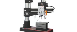
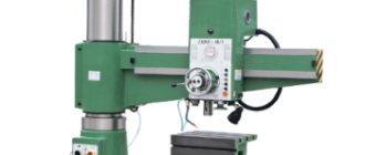
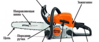
In drilling machines, the main movement and the feed movement are communicated to the tool. General purpose machines include vertical drilling and radial drilling machines. In Fig. Figure 1 shows a general view of a radial drilling machine. The machine consists of a foundation slab 1 with a fixed column installed on it, onto which a hollow sleeve 2 is placed. The sleeve can be rotated around the column by 360°. A horizontal sleeve (traverse) 4 is put on the sleeve, which can be raised and lowered along the column using the vertical screw of the movement mechanism 3.
The sleeve with sleeve is secured to the column (column clamp) using a split ring, which is tightened by means of a differential screw rotated manually or by a separate electric motor. The spindle head (drill head) 5 can move in the radial direction along the horizontal guides of the sleeve. The workpiece is installed on the table 8. The main electric motor 6 imparts rotation to the spindle 7 and feeds the tool (drill).
In electrical engineering, drilling machines are used to drill holes in the ends of the frames of electrical machines, in bearing shields, paws, etc.
The spindle speed of the 2A55 radial drilling machine is controlled mechanically using a gearbox in the range from 30 to 1500 rpm (12 speeds). The feed drive of the radial drilling machine is made from the main engine D1 through the feed box. The feed speed is adjustable from 0.05 to 2.2 mm/rev, the highest feed force Fп=20000 N.
The traverse of the radial drilling machine can rotate around the axis of the column by 360° and moves vertically along the column by 680 mm at a speed of 1.4 m/min. The traverse is clamped to the column automatically. All machine controls are concentrated on the drilling head, which provides a significant reduction in auxiliary time when working on the machine.
All electrical equipment of a radial drilling machine, with the exception of the electric pump, is installed on the rotating part of the machine, so the 380 V mains voltage is supplied through the input switch BB to the ring current collector KT and then through the brush contact to the distribution cabinet installed on the traverse.
Before starting the machine, it is necessary to clamp the column and spindle head, which is done by pressing the Clamp button. The short-circuit contactor receives power and uses the main contacts to turn on the DZ and D4 motors, which drive the hydraulic clamping devices. At the same time, through the auxiliary contact of the short-circuit contactor, the RN relay is switched on, preparing power to the control circuits through its contact after stopping the action on the Clamp button and turning off the short-circuit contactor.
To press out the column and spindle head if it is necessary to move them, press the Spin button, which loses power to the PH relay, which makes it impossible to work on the machine when the column and spindle head are pressed out.
The motors of the spindle D1 and the movement of the traverse D2 are controlled using a cross switch KP, the handle of which can be moved into four positions: Left, Right, Up and Down, thus closing the contacts KP1—KP4, respectively. So, in the Left position of the handle, the KShV contactor is turned on, and the spindle rotates counterclockwise. If the handle is moved to the Right position, the KShV contactor is turned off, the KShN contactor is turned on, and the machine spindle will rotate clockwise.
When the handle of the gearbox cross switch is set, for example, to the Up position, the KTV contactor turns on the D2 motor. In this case, the lead screw of the movement mechanism first rotates idle, moving the nut sitting on it, which causes the traverse to be pressed out (in this case, the PAZ-2 contact of the automatic clamping switch is closed), after which the traverse is lifted.
When the traverse reaches the required level, the gearbox handle is moved to the middle position, so the KTV contactor is turned off, the K.TN contactor is turned on and the D2 engine is reversed. Reversing it is necessary to automatically clamp the traverse by rotating the lead screw in the opposite direction and moving the nut to the clamping position, after which the engine is turned off by the open PAZ-2 contact. If you now set the gearbox switch handle to the Down position, the traverse will first be pressed out, and then lowered, etc.
The movement of the traverse in extreme positions is limited by the limit switches VKV and VKN, which break the power circuits of the KTV or KTN contactors.
ELECTRIC DRIVE AND CONTROL DIAGRAM OF RADIAL DRILLING MACHINE
The popularity of the 2M vertical drilling machine is also evidenced by the fact that even after a complete breakdown, which happens extremely rarely, users try to find a unit of a similar model, rather than purchasing cheap and low-quality devices from Chinese manufacturers or expensive European equipment.
Among the most significant advantages that the 2M model drilling machine has, it is necessary to highlight the following. The vertical drilling machine of the model in question is not without its shortcomings, which are not mentioned in the passport. The main disadvantage of this equipment is that it is already obsolete. Modern devices of this category, the production of which uses new technological approaches and innovative kinematic schemes, surpass 2M in processing accuracy, efficiency and productivity.
To get a complete picture of the 2M drilling machine, it is enough to study several reviews from those who have already worked on such equipment and can objectively judge its characteristics and technical capabilities. Drilling machines are used to produce through and blind holes in parts using drills, for reaming and finishing holes previously acquired by casting or stamping, and for performing other operations.
In drilling machines, the main movement and the feed movement are communicated to the tool. General purpose machines include vertical drilling and radial drilling machines.
The machine consists of a foundation slab 1 with a fixed column installed on it, onto which a hollow sleeve 2 is mounted.
Table of contents
The 2A554 radial drilling machine is designed for drilling holes in solid material, drilling, countersinking, and also tapping threads.
Increasing the productivity and functionality of the machine is possible with the use of devices and special tools that allow you to perform turning of internal grooves, cutting round plates, as well as work typical for boring machines.
Kronas fittings at affordable prices here!
Workspace dimensions
Design of a radial drilling machine 2A554
- Plate;
- Cooling system;
- Grounding;
- Electrical equipment;
- Base, column;
- Sleeve clip;
- Sleeve;
- Hydraulic clamp;
- Current collector;
- Hydro station;
- Gearbox;
- Lifting mechanism;
- Electrical equipment;
- Manual movement mechanism;
- Steering device;
- Spindle;
- Feed mechanism;
- Friction clutch control;
- Electrical equipment;
- Accelerated spindle retraction;
- Counterweight;
- Head clamp;
- Pumping station;
- Lubrication system;
- Hydrocommunications;
- Main cylinder;
- Gyro selector drive;
- Hydropremelector;
- Friction clutch;
- Gearbox;
- Feedbox 24 speeds;
- 12 speed feed box;
- Drill head;
- Hydropanel
Kinematic diagram of the radial drilling machine 2A554
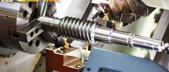
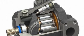
Spindle of radial drilling machine
The spindle of the machine 1 is located in a retractable quill 5. In the front support, in addition to two radial ball bearings, there is also a thrust bearing 3, which takes up the axial load when drilling.
Node design
The main load of the 2A135 vertical drilling machine is carried by a column and a slab. But thanks to the housing design and large mass, loads and vibrations are dampened, and rigidity increases.
Spindle
The spindle unit is a rigid structure, therefore, to increase the processing accuracy, precision bearings are installed in it. Its design allows you to perform the following actions:
- turning on the approach after performing a quick approach (automatically);
- turning off the supply upon reaching the set processing depth;
- manual movement is carried out by the steering wheel;
- The steering wheel is equipped with an automatic drive activation device.
Spindle assembly of vertical drilling machine 2A135
Cooling
The cooling system for the tool and workpiece is similar to those installed on other vertical drilling machines. The container is the internal cavity of the mounting plate. A pump is mounted on it, and along the body there is a distribution of pipelines with taps that regulate the supply of coolant.
Cooling system design for vertical drilling machine 2A135
Gearbox and feeds
The combined gearbox and feeds form all the working movements of the machine. The main, main movement is the circular rotation of the spindle with the working tool. The rotation from the electric motor is transferred to the gearbox via a belt drive. On the spindle, rotation at a given speed is generated by two sets of gear blocks.
Auxiliary movement – movement of the tool. Rotation is removed from the shaft that transmits rotation to the spindle. The selection of feed and its activation is carried out by clutches. According to the diagram, 12 speeds are possible, but due to the fact that two are combined, the result is 11.
The device of the gearbox of the drilling machine 2A135
The spindle head has manual movement to increase the distance between the table plane and the end of the spindle. This allows you to install large parts. Rotation of the handle sets in motion a gear that moves along a rack. This moves the spindle head.
Radial drilling machine 2M55
The 2M55 radial drilling machine has found application not only in single and small-scale production, but also in serial and large-scale production, provided that it is retrofitted with specialized devices.
The manufacturer and founder of the production of machine tools is located in Ukraine, the city of Odessa. Production has been established since 1946.
Purpose
As the name suggests, this model performs operations related to the processing of holes. Using various tools, holes are processed using: drilling and reaming, countersinking and counterbore, and then reaming. Also on the machine, the ends are processed by trimming and threads are cut in the body of the part.
Radial drilling machines 2M55, the equipment of which can be expanded with specialized devices, perform operations of turning grooves inside holes, cutting holes on a metal sheet, and can also carry out high-speed processing.
The main advantage of radial drilling machines is the absence of movement of the workpiece during processing. Heavy or large parts are installed once, and processing is carried out by moving the tool over the surface of the part. This method reduces the loss of time for reinstallation and eliminates the inconvenience of turning.
Device design and features
The device of this type of unit includes the following elements:
- spindle;
- gearbox;
- base, workplace and column;
- drive unit;
- head for securing the tool;
- electrical cabinet;
- cooling system;
- gearbox;
- system that controls speeds and feeds;
- plunger oil pump.
Plunger oil pump
The technical characteristics of vertical drilling machines indicate their versatility. These devices can perform not only drilling, but also countersinking, reaming, threading and reaming of holes.
This is due to the use of durable and hard tools made from well-cutting steels.
The ability to cut threads with machine taps is ensured by the reversibility of the spindle, thanks to which it can move in both directions.
The main features of the device are as follows:
- machine weight - 1199 kg;
- spindle torque can reach a maximum of 399 Nm;
- presence of a spindle stop system;
- the maximum permissible force at which the feed is performed is 15 kN;
- the use of an electric pump of the X14-22M type as part of the structure to transfer the cooling liquid to the processing site;
- The dimensions of the desktop are 449*499 mm, on the surface of which there are three grooves in the shape of the letter “T”.
One of the main technological features of the machine is its 100% manual control. All stages of work are adjusted manually, and the spindle feed is carried out mechanically.
General characteristics of the unit include three large parts:
- workplace-table on which the part to be processed is located;
- stable cast iron frame with space inside for electrical equipment;
- a drilling head with a spindle that moves vertically using a worm shaft.
Technical parameters and characteristics
Radial drilling machine 2M55, the technical characteristics of which reflect the following parameters:
- accuracy class – N according to GOST 8-71;
- maximum permissible drilling size: cast iron – 63 mm;
- steel – 50 mm;
- swing - 1600 mm;
- cone on the spindle for tool mounting - Morse 5 according to GOST 24644-81;
- number of switchable speeds – 21;
- setting speed range – min 20 min-1, max 2000 min-1;
- number of innings – 12;
- feed range – 0.056-2.5 mm/rev;
- feed force when cutting, max – 20000 N;
- torque - 7000 N•m.
Parameters of electrical elements:
- general network, current - three-phase alternating;
- electric motor power:
- main - 4000 W;
- sleeve drive - 2200 W;
- column clamp - 500 W;
- drill clamp – 500 W;
- coolant stations - 125 W;
- speed switching – 150 W;
- feed switching – 150 W;
- Dimensions of the machine, LxWxH - 2545x1000x3315 mm;
- equipment weight - 4.1 tons.
Specifications
The technological capabilities and performance characteristics of the 2A135 vertical drilling machine are shown in the design parameters:
Basic data
- accuracy class according to GOST 8-71 – N (normal);
- maximum resulting hole size, mm: steel 45 – 35;
- cast iron – 45;
- the largest - 1130;
Table
- mounting plate WxD – 450x500;
- vertical table travel – 325;
- T-shaped grooves, quantity – 3.
Headstock
- landing cone for the tool in the spindle - Morse 4 according to GOST 24644-81;
- number of revolution speeds – 9;
- installation speeds: 68 rpm;
- 100 rpm;
- 140 rpm;
- 195 rpm;
- 175 rpm;
- 400rpm;
- 530 rpm;
- 750 rpm;
- 1100 rpm;
Parameters of electrical elements
- supply current - three-phase, alternating;
- power of electric motors: main - 4500 W;
- coolant stations (X14-22M) - 125 W.
Dimensions
- overall dimensions of the machine, LxWxH - 1240x810x2500 mm;
- assembled equipment weight - 1.3 tons.
Electrical equipment
On the 2M55 machine, the electrical diagram shows the control of the working parts. The electrical circuit diagram is shown in the figure.
Electrical diagram of the 2M55 machine
- Safety of work on the machine is ensured by locks.
- If the control device is in the on state, then power will not be supplied to the engine until the control handle is set to the neutral position.
- Switching gears is impossible while the hydraulic preselector is operating. The signal is not supplied to the spool coil.
- The movement of the hose along the column is limited by two limit switches.
By supplying power to the electrical circuit, the main engine and the hydraulic motor are turned on, and the machine goes into setup mode.
Clamping and release of the drilling unit and column are hydraulic. The electrical circuit controls the hydraulic spool coils. The possibility of separate spinning of the drilling unit is organized.
You can only rotate the sleeve and move the drilling head manually by pressing the release button. The movement of the hose along the column is carried out by a separate M2 engine.
The circuit provides a preselective preset of spindle rotation speeds and working feeds. These operations are performed while the machine is running. At the end of processing, the signal from the relay is sent to the M5 engine. It moves the switching mechanism until the positions of switch B11 are matched with switch B13. After this, switching to the specified modes occurs.
The spindle has reverse rotation.
The load on the spindle motor is monitored using an ammeter IP1.
Online electrical magazine
Drilling machines are used to produce through and blind holes in parts using drills, for reaming and finishing holes previously acquired by casting or stamping, and for performing other operations. In drilling machines, the main movement and the feed movement are communicated to the tool. General purpose machines include vertical drilling and radial drilling machines.
In Fig. Figure 1 shows a view of a radial drilling machine. The machine consists of a foundation slab 1 with a fixed column installed on it, onto which a hollow sleeve 2 is mounted. The sleeve can be rotated around the column by 360°. A horizontal sleeve (traverse) 4 is put on the sleeve, which can be raised and lowered along the column using a vertical screw of the movement mechanism 3.
Fastening the sleeve with a sleeve to the column (column clamp) is done with a split ring, which is tightened by means of a differential screw rotated manually or by a separate electric motor. The spindle head (drill head) 5 can move in a circular direction along the horizontal guides of the sleeve. The workpiece is installed on the table 8. From the head electric motor 6, rotation is transmitted to the spindle 7 and the tool (drill) is fed.
In electrical engineering, drilling machines are used to drill holes in the ends of the frames of electronic machines, in bearing shields, paws, etc.
Let's look at the electric drive and control circuit (Fig. 2) of a radial drilling machine model 2A55, created for processing holes with a diameter of up to 50 mm with high-speed steel drills. The machine has 5 asynchronous squirrel-cage motors: rotation of the spindle D1 (4.5 kW), movement of the traverse D2 (1.7 kW), hydraulic clamping of the column DZ and spindle head D4 (0.5 kW each) and electric pump D5 (0.125 kW).
The spindle speed of the 2A55 radial drilling machine is controlled mechanically using a gearbox in the range from 30 to 1500 rpm (12 speeds). The feed drive of the radial drilling machine is made from the head motor D1 through the feed box. The feed speed is adjustable from 0.05 to 2.2 mm/rev, the highest feed force Fп=20000 N.
The traverse of the radial drilling machine can rotate around the axis of the column by 360° and moves vertically along the column by 680 mm at a speed of 1.4 m/min. Clamping of the traverse on the column is done automatically. All machine controls are concentrated on the drilling head, which provides a significant reduction in auxiliary time when working on the machine.
All electrical equipment of the radial drilling machine, except for the electric pump, is installed on the rotating part of the machine, therefore the 380 V mains voltage is supplied through the input switch BB to the ring current collector KT and then through the brush contact to the distribution cabinet installed on the traverse.
Before operating the machine, you need to clamp the column and spindle head, which is done by pressing the Clamp button. The short circuit contactor receives power and the main contacts turn on the motors DZ and D4, which activate the hydraulic clamping devices. Immediately through the auxiliary contact of the short-circuit contactor, the RN relay is switched on, preparing power to the control circuits through its own contact after stopping the action on the Clamp button and turning off the short-circuit contactor.
To press out the column and spindle head as needed to move them, press the Spin button; in this case, the power supply to the PH relay is lost, which makes it impossible to work on the machine with the column and spindle head pressed out.
Control of the spindle motors D1 and the movement of the traverse D2 is done using a cross toggle switch KP, the handle of which can be moved in four positions: To the left, to the right, Up and Down, while closing the contacts KP1 - KP4 respectively. So, in the position of the handle on the left, the KShV contactor is turned on, and the spindle rotates counterclockwise. If the handle is moved to the Right position, the KShV contactor is turned off, the KShN contactor is turned on, and the machine spindle will rotate clockwise.
When setting the handle of the cross toggle switch of the gearbox, for example, to the Up position, the KTV contactor switches on the D2 engine. In this case, the lead screw of the movement mechanism first turns idle, moving the nut sitting on it, which causes the traverse to be pressed out (with all this, the PAZ-2 contact of the automatic clamp toggle switch closes), after which the traverse rises.
When the traverse reaches the desired level, the gearbox handle is moved to the middle position, therefore the KTV contactor is turned off, the K.TN contactor is turned on and the D2 engine is reversed. Its reverse is needed to implement automatic clamping of the traverse due to the rotation of the lead screw in the opposite direction and movement of the nut to the clamping position, after which the engine is turned off by the open PAZ-2 contact. If you now set the gearbox toggle switch knob to the Down position, then first the traverse will be pressed out, and then it will be lowered, etc.
The movement of the traverse in the last positions is limited by the limit switches VKV and VKN, which break the power circuits of the KTV or KTN contactors.
Protection against small short circuits in power circuits, control and lighting circuits is done by fuses Pr1 - Pr4. The spindle motor is protected from overload by a thermal relay RT. The RN relay provides zero protection, preventing the self-starting of motors D1 and D2, turned on by the gearbox toggle switch, when the supply voltage is removed and then restored again. The control circuit can only be restored by pressing the Clamp .
Controls
For the 2M55 machine, the operating manual describes how to control the machine.
Machine controls 2M55
The figure shows the following controls located on the drill head:
- accelerated spindle approach, connection of working feed – 5;
- drilling depth setting – 6;
- feed blocking during thread cutting – 7;
- latch for regulating the lowering of the coolant valve – 8;
- spinning the drill head – 9;
- spinning the column together with the drilling head – 10;
- column clamp together with drilling head – 11;
- connection between the dial and the feed mechanism -12;
- dial fine adjustment -13;
- ammeter (load indicator) – 14;
- counterweight spring tension regulator – 15;
- pre-dial indicator – 16;
- sleeve rise – 17;
- spindle shutdown – 18;
- pre-dial handle – 19;
- main engine start – 20;
- lowering the sleeve – 21;
- feed preset – 22;
- stop button – 23;
- reverse – 25;
- local lighting – 26;
- turning on mechanical feed – 29;
- precise manual feed – 30;
- coolant valve – 31;
- flywheel for drilling unit movement - 32.
Cooling system
A container for coolant is located in the cavity of the plate. The coolant is supplied to the cutting zone, to the tip, by a pump through a hose. Depending on the dimensions of the part, you can adjust the height of the tip.
In 2M55, the amount of coolant is poured depending on the pump performance. Its productivity is 22 l/min.
Machine cooling system
List of cooling system elements:
- lid closing the container -1;
- pump assembly – 2;
- hose – 3;
- tee – 4;
- lowering regulator – 5;
- bar – 6;
- tip – 7;
- swivel joint – 8;
- grid – 9.
Operating principle and scope of use of drilling machines
Most machines for vertical drilling can be seen in industrial enterprises; they have wide functionality. Household vertical drilling machines, although less functional, are indispensable in many cases. It is by the example of their design that it will be convenient for us to consider the operating principle of these units.
The main operations that a vertical drilling machine are two spindle movements: vertical and rotational. Therefore, in fact, the machine is called vertical drilling.
The rotation of the spindle is ensured by an electric motor (power range from 250 to 1000 W for different household machines), which transmits torque to the belt drive shaft. And the steering wheel is responsible for vertical movement - a handle on the side of the body.
Household drill chuck
To start drilling, use a special wrench to install the bit into a chuck, similar to the clamping device found in a hand drill. The chuck allows the use of drills with a diameter of up to 12 mm, but the minimum drill size (up to 3 mm in diameter) is not clamped by all devices, keep this in mind when choosing.
The spindle speed can be adjusted, but only manually. Belt drive shafts have pulleys with steps of different diameters. By throwing the belt on the pulleys from one groove to another with the engine off, we can obtain higher or lower speeds within the range of 450-3000 rpm.
Belting
Depending on the machine model, you can drill parts of different heights: from 20 to 90 mm. This is influenced by the height of the stand, and therefore the distance over which the drill head can move. It can be secured with a handle and a fixing screw.
An important parameter for technological operations on a machine is the drill overhang - the distance between the stand and the axis of the drilling attachment. The standard drill reach for household tools is 10-20 cm, but it is desirable that it be maximum.
Spring loaded feed handle
The operating principle also provides for vertical movement of the drill using a spring-loaded handle. This function facilitates and speeds up the operator’s work, since after moving the drill with the handle, it automatically returns to its previous position. There are models of machines on which it is possible to cut threads in a hole, thanks to the equipment with an electric motor with reverse start.
Possible faults
2M55 malfunctions are detected by pressing the control buttons. The most common reasons are:
- absence of movement or activation of mechanisms when pressing keys (no power in the electrical circuit);
- incorrect choice of speeds and feeds after preset (adjustment failure);
- lack of rotation on the spindle (low pressure in the hydraulic system);
- cutting off the feed when drilling, triggering a safety device (the tool has become dull, the cutting mode has not been selected correctly).
Other possible malfunctions can be found in the operating instructions for the radial drilling machine.
The device of a vertical drilling machine
Home » Articles » Professionally about metalworking » Drilling machinesWe recommend purchasing:
Installations for automatic welding of longitudinal seams of shells - in stock!
High performance, convenience, ease of operation and reliability in operation.
Welding screens and protective curtains are in stock!
Radiation protection when welding and cutting. Big choice. Delivery throughout Russia!
In vertical drilling machines, the main movement is the rotation of the spindle with the tool fixed in it, and the feed movement is the vertical movement of the spindle. The workpiece is usually installed on the machine table or on the foundation plate if it has large overall dimensions. The alignment of the workpiece holes and the spindle is achieved by moving the workpiece.
The main components are located on the bed (column) of 1 machine (Fig. 6.4). The bed has vertical guides along which the table 9 and the drilling head 3 move, carrying the spindle 7 and the motor 2. The gearboxes and feeds are controlled by handles 4, manual feed is carried out by the steering wheel 5. The depth of processing is controlled using the dial 6. Electrical equipment is placed in the niche and counterweight. In some models, a cabinet 12 is provided for electrical equipment. The base plate 11 serves as the support of the machine. In medium and heavy machines, its upper plane is used to install workpieces. Sometimes the internal cavities of the foundation slab act as a coolant reservoir. The machine table is used to secure the workpiece. It can be movable (from the handle 10 through a bevel pair of gears and a lead screw), fixed (removable) or rotary (folding). The table is mounted on the frame guides or made in the form of a cabinet mounted on a foundation slab.
The coolant is supplied by an electric pump through hose 8. The drill head components are also lubricated using a pump. The remaining components are lubricated manually.
The drilling head (Fig. 6.5) is a cast iron casting in which speed and feed boxes, a spindle and other mechanisms are mounted. The gearbox includes two- and three-ring blocks of gears, which are switched using a handle 15 and impart various angular speeds to the spindle. This is done by a cam-gear mechanism that transmits movement to the rods on which the forks are attached, connected to switchable blocks. For example, the spindle of a machine model 2N135 has twelve speed levels (from 31.5 to 1400 min-1), provided by a gearbox and a two-speed electric motor 16. The gearbox is attached to the drilling head 4 from above.
The machine spindle receives rotation from a spline gear included in gearbox 1, which allows the spindle to simultaneously rotate and move in the axial direction together with the sleeve. Axial loads arising during drilling are absorbed by bearings mounted in the spindle sleeve.
Equation of the kinematic chain of spindle rotation
Feed box 2 provides nine feeds in the range of 0.1 ... ... 1.2 mm/rev. Feed switching is carried out by handle 3. The feed box receives rotation from the shaft of the VIII gearbox, connected to the spindle by a constant transmission with gears z = 34 and z = 60.
Equation of the kinematic chain of spindle feed motion
The transmission of motion from the steering wheel 5 of the mechanism 6 through the rack and pinion gear 7 directly to the sleeve 9 of the spindle 8 is carried out when the Mf clutch is engaged. The figure shows a machine spindle with a four-spindle head installed on it.
To remove the tool from the spindle cone, a special mechanism is used, consisting of a knockout cam 18, a holder 17 and a casing 19. When the spindle is lifted, the holder is held back by the lower wall of the drilling head housing, and the spindle, continuing to go up, carries with it a cam, which is hinged in it . The end of the cam rests on the stopped holder, the cam rotates and squeezes the tool out of the spindle cone.
The machines are equipped with devices to automatically turn off the mechanical feed when a given processing depth is reached. The processing depth is set using mechanism 12 mounted on the left side of the head. The mechanism is driven by a gear pair and has a disk with cams for setting the drilling depth and automatic shutdown with reverse, as well as a dial for visual reference.
The time spent on auxiliary moves is reduced thanks to the mechanism 13 for accelerated movement of the spindle with an electric drive 14. The universal machine is controlled using a push-button station 11, and the automated machine is controlled by a panel 10.
Technical characteristics and passport of the radial drilling machine 2A554
The 2A554 radial drilling machine, produced by the Odessa Radial Drilling Machines Plant, was created for processing parts of significant size and weight. Such workpieces are quite difficult to process using a conventional drilling machine, since the operator has to expend serious effort to move them along the surface of the work table. The design features of the machine model 2A554 allow, by manipulating only the working part of the equipment, to drill almost any part of the part, as well as to effectively perform a number of other technological operations.
Machine appearance
According to the technical data sheet, the equipment of this model is used for:
- drilling holes of various diameters;
- opening holes;
- countersinking;
- cutting in internal thread holes;
- end processing (trimming).
It is possible to process large-sized workpieces on such equipment efficiently and without significant labor costs on the part of the operator due to the fact that its spindle head has several degrees of freedom.
The main part of the controls of the radial drilling machine model 2A554, in contrast to drilling devices of a standard design, is concentrated in the working head. The latter is located on a special traverse (sleeve), rotating together with the column on which it is mounted. The traverse, in addition to rotation, can move along the column along a vertical axis, and the drilling head can move along the sleeve in a horizontal plane.
Machine controls
Drilling machine diagram
A horizontal traverse sleeve 4 is put on the sleeve, which can be raised and lowered along the column using a vertical screw of the movement mechanism 3. The sleeve with the sleeve is secured to the column and the column is clamped with a split ring, which is tightened by means of a differential screw rotated manually or by a separate electric motor.
The spindle head and drill head 5 can move in a circular direction along the horizontal guides of the sleeve.
The workpiece is installed on the table 8. From the head electric motor 6, rotation is transmitted to the spindle 7 and the drill tool is fed. In electrical engineering, drilling machines are used to drill holes in the ends of the frames of electronic machines, in bearing shields, paws, etc. Let's look at the electric drive and control circuit Fig. The machine has 5 asynchronous squirrel-cage motors: spindle rotation D1 4.5 kW, traverse movement D2 1.7 kW, hydraulic clamping of the DZ column and spindle head D4 0.5 kW each and electric pump D5 0, kW.
The feed drive of the radial drilling machine is made from the head motor D1 through the feed box. Clamping of the traverse on the column is done automatically. All machine controls are concentrated on the drilling head, which provides a significant reduction in auxiliary time when working on the machine.
All electrical equipment of the radial drilling machine, except for the electric pump, is installed on the rotating part of the machine, therefore network voltage B is supplied through the input switch BB to the ring current collector KT and further through the brush contact to the distribution cabinet installed on the traverse. Before operating the machine, you need to clamp the column and spindle head, which is done by pressing the Clamp button. The short circuit contactor receives power and the main contacts turn on the motors DZ and D4, which activate the hydraulic clamping devices.
Immediately through the auxiliary contact of the short-circuit contactor, the RN relay is switched on, preparing power to the control circuits through its own contact after stopping the action on the Clamp button and turning off the short-circuit contactor. To press out the column and spindle head as needed to move them, press the Spin button; in this case, the power supply to the PH relay is lost, which makes it impossible to work on the machine with the column and spindle head pressed out.
Control of the spindle motors D1 and the movement of the traverse D2 is done using a cross toggle switch KP, the handle of which can be moved in four positions: To the left, to the right, Up and Down, while closing the contacts KP1 - KP4 respectively.
Drilling machines are used to produce through and blind holes in parts using drills, to ream and finish holes previously obtained by casting or stamping, and to perform other operations. In drilling machines, the main movement and the feed movement are communicated to the tool. General purpose machines include vertical drilling and radial drilling machines.
So, in the position of the handle on the left, the KShV contactor is turned on, and the spindle rotates counterclockwise. If the handle is moved to the Right position, the KShV contactor is turned off, the KShN contactor is turned on, and the machine spindle will rotate clockwise. In this case, the lead screw of the movement mechanism first spins idle, moving the nut sitting on it, which causes the traverse to be pressed out; at the same time, the PAZ-2 contact of the automatic clamp toggle switch closes, after which the traverse rises.
When the traverse reaches the desired level, the gearbox handle is moved to the middle position, therefore the KTV contactor is turned off, the K.TN contactor is turned on and the D2 engine is reversed. Its reverse is needed to implement automatic clamping of the traverse due to the rotation of the lead screw in the opposite direction and movement of the nut to the clamping position, after which the engine is turned off by the open PAZ-2 contact.
If you now set the gearbox toggle switch knob to the Down position, the traverse will first be pressed out, and then lowered, etc. Protection against small short circuits in power circuits, control and lighting circuits is done by fuses Pr1 - Pr4. The spindle motor is protected from overload by a thermal relay RT. The RN relay provides zero protection, preventing the self-starting of motors D1 and D2, turned on by the gearbox toggle switch, when the supply voltage is removed and then restored again.
Technical characteristics of the vertical drilling machine 2N118
The control circuit can only be restored by pressing the Clamp button again. A home drilling machine is simply a drilling machine, an equipment that anyone who has ever made anything feels an urgent need for. Craftsmen sometimes make drilling machines with 2-speed gears, workpiece tables with more than 3 degrees of freedom, and even two-axis CNC drilling and milling machines, see.
But in this publication we will look at how to make a drilling machine with your own hands, which simply drills and mills - but accurately, cleanly, and confidently maintains its accuracy for a long time, subject to occasional short-term overload: stable processing accuracy is the main requirement for metal-cutting equipment. Which in amateur designs is carried out, unfortunately, most often only due to a random coincidence of circumstances.
Beginners always think that woodworking is easy and simple. The spoiled workpiece will be suitable for small crafts or fuel. Perhaps this is why there has been a real craze lately: homemade machines with critical wooden parts. As a result, monsters sometimes appear that would probably surprise even Archimedes, see. At this point, the question of using wood as the main structural material of the machine is closed without discussing the fact that wood, moreover, is orders of magnitude lighter than metal, deforms, wears out and is damaged.
Well, for lovers of deep inner self-satisfaction in products - free will for their money and work. Fantasy is an indispensable condition for any creative success, but in mechanical engineering it is useless without accurate calculations and comparison with solutions proven by experience.
The history of machine tool construction goes back thousands of years - foot-driven bow lathes and drilling machines were used already at the end of the Stone Age. On the topic of this article, a proven sample is an industrial-style desktop vertical drilling machine.
We will refer to it when choosing and deciding how best to make a drilling machine with our own hands: there are only a few examples of drilling machines in use that have exceeded , and they still maintain accuracy. Its main modules are a bed, a column, a console and a table for a part. The components of the main nodes are slightly highlighted in color, and their components are brighter in color.
File information
The simplest table besides a wooden block is a vice. The rotary-sliding table allows, in addition to drilling, to perform some milling operations.
The bed, as a rule, is tightly attached to a workbench or other. In operation, the console, using a lifting and rotating slider mechanism, is installed in the required position in accordance with the size and configuration of the workpiece, and fixed. The spindle is fed into the working stroke by a separate feed mechanism.
Free archive of articles articles in the Archive. Alphabetical index of articles in books and magazines. Free technical library, Encyclopedia of radio electronics and electrical engineering. Comments on the article. See other articles in the Home Workshop section.
In amateur and industrial designs for home use, the lifting and turning mechanism is most often the operator’s hand, and the lock is a screw clamp of the slide, see.
But what must certainly be in the design of a drilling machine according to the requirements of the same safety regulations is a bumper device or just a bumper: if you throw the feed handle, the spindle or carriage along with it should automatically bounce up until it stops. In home drills, the chipper is most often a spring installed in a suitable place, see.
Note: industrial production, sale and use at enterprises and workshops of individual entrepreneurs of drilling machines without a fender device are prohibited by PTB. An electric drill is a ready-made drive, gear, spindle and chuck in a monoblock.
Place it on the carriage of the machine and you can drill. In terms of accuracy, the solution, generally speaking, is not optimal, see. Therefore, frames for installing a drill are now sold only on the street from trays; prices are affordable. When choosing one to make a drilling machine from a drill, be guided primarily by the operating mode of the equipment; The price also depends on it:.
Note: as a rule, drill stands are optionally offered with a rotary-sliding table for the part, which allows for certain types of milling. The design needs to be checked. The second is console play. We take it by the far end, swing it up and down and to the sides while holding the latch.
Next is an inspection of the structure, see. For regular drilling, the one shown in pos. The ideal option is at pos. And here is a sample for pos.
Firstly, the collar of its column is low and its fastening is unreliable. Moreover, they will concentrate where the tide under the column is shown by the arrows to be too narrow and from there they will go straight into the column and table.
Let’s say the price for the machine you like doesn’t suit you. Then the first thing we do is find out if there is a master within reach who owns a lathe with increased precision no rougher than 0.02 mm.
Which, by the way, is not a fact - a high-precision machine is very expensive and never pays off with the flow of regular orders. But let's say he was found.
Design of radial drilling machine model 2A554
The elements that make up the design of the 2A554 radial drilling machine are:
- a foundation plate that serves both as the base of the machine and as a base for placing the workpiece being processed (to ensure fixation of the latter, there are several T-shaped grooves on the upper surface of such a plate);
- a column that ensures rotation of the traverse and its movement along a vertical axis (for easy, smooth and accurate rotation, a bearing unit is mounted at the base of the column);
- traverse mounted on a column;
- a working head that moves in a horizontal plane along the traverse guides;
- a mechanism that ensures rotation of the traverse and its fixation in a certain position;
- main electric motor, drive mechanism, feed control box.
Main components of the machine (click to enlarge)
The controls are located on the side of the drilling head of the 2A554 radial drilling machine, which makes working on it convenient and efficient. The operator sets the modes before starting processing, which makes it possible to increase not only its productivity, but also the accuracy of execution.
Purpose of controls (click to enlarge)
Drilling machines are used to produce through and blind holes in parts using drills, to ream and finish holes previously obtained by casting or stamping, and to perform other operations. In drilling machines, the main movement and the feed movement are communicated to the tool. General purpose machines include vertical drilling and radial drilling machines.
In Fig. Figure 1 shows a general view of a radial drilling machine. The machine consists of a foundation slab 1 with a fixed column installed on it, onto which a hollow sleeve 2 is placed. The sleeve can be rotated around the column by 360°. A horizontal sleeve (traverse) 4 is put on the sleeve, which can be raised and lowered along the column using the vertical screw of the movement mechanism 3.
The sleeve with sleeve is secured to the column (column clamp) using a split ring, which is tightened by means of a differential screw rotated manually or by a separate electric motor. The spindle head (drilling head) can move in the radial direction along the horizontal guides of the sleeve 5. The workpiece is installed on the table 8 Magnetic drilling machines can be purchased here. . The main electric motor 6 imparts rotation to the spindle 7 and feeds the tool (drill).
In electrical engineering, drilling machines are used to drill holes in the ends of the frames of electrical machines, in bearing shields, paws, etc.
Let's consider the electric drive and control circuit (Fig. 2) of a radial drilling machine model 2A55, designed for processing holes with a diameter of up to 50 mm with high-speed steel drills. The machine has five asynchronous squirrel-cage motors: rotation of the spindle D1 (4.5 kW), movement of the traverse D2 (1.7 kW), hydraulic clamping of the column DZ and spindle head D4 (0.5 kW each) and electric pump D5 (0.125 kW).
The spindle speed of the 2A55 radial drilling machine is controlled mechanically using a gearbox in the range from 30 to 1500 rpm (12 speeds). The feed drive of the radial drilling machine is made from the main engine D1 through the feed box. The feed speed is adjustable from 0.05 to 2.2 mm/rev, the highest feed force Fп=20000 N.
The traverse of the radial drilling machine can rotate around the axis of the column by 360° and moves vertically along the column by 680 mm at a speed of 1.4 m/min. The traverse is clamped to the column automatically. All machine controls are concentrated on the drilling head, which provides a significant reduction in auxiliary time when working on the machine.
All electrical equipment of the radial drilling machine, with the exception of the electric pump, is installed on the rotating part of the machine, so the 380 V mains voltage is supplied through the input switch BB to the ring current collector KT and then through the brush contact to the distribution cabinet installed on the traverse.
Before starting to operate the machine, it is necessary to clamp the column and spindle head, which is done by pressing the Clamp button. The short-circuit contactor receives power and uses the main contacts to turn on the DZ and D4 motors, which drive the hydraulic clamping devices. At the same time, through the auxiliary contact of the short-circuit contactor, the RN relay is switched on, preparing power to the control circuits through its contact after stopping the action on the Clamp button and turning off the short-circuit contactor.
To press out the column and spindle head, if it is necessary to move them, press the Spin button, which loses power to the PH relay, which makes it impossible to work on the machine when the column and spindle head are pressed out.
The motors of the spindle D1 and the movement of the traverse D2 are controlled using a cross switch KP, the handle of which can be moved in four positions: Left, Right, Up and Down, thus closing the contacts KP1—KP4, respectively. So, in the Left position of the handle, the KShV contactor is turned on, and the spindle rotates counterclockwise. If the handle is moved to the Right position, the KShV contactor is turned off, the KShN contactor is turned on, and the machine spindle will rotate clockwise.
When the handle of the gearbox cross switch is set, for example, to the Up position, the KTV contactor turns on the D2 motor. In this case, the lead screw of the movement mechanism first rotates idle, moving the nut sitting on it, which causes the traverse to be pressed out (in this case, the PAZ-2 contact of the automatic clamping switch is closed), after which the traverse is lifted.
When the traverse reaches the required level, the gearbox handle is moved to the middle position, so the KTV contactor is turned off, the K.TN contactor is turned on and the D2 engine is reversed. Reversing it is necessary to automatically clamp the traverse by rotating the lead screw in the opposite direction and moving the nut to the clamping position, after which the engine is turned off by the open PAZ-2 contact. If you now set the gearbox switch handle to the Down position, the traverse will first be pressed out, and then lowered, etc.
The movement of the traverse in extreme positions is limited by the limit switches VKV and VKN, which break the power circuits of the KTV or KTN contactors.
Protection against short circuits in power circuits, control and lighting circuits is provided by fuses Pr1 - Pr4. The spindle motor is protected from overload by a thermal relay RT. The RN relay provides zero protection, preventing self-starting of engines D1 and D2, turned on by the gearbox switch, when the supply voltage is removed and then restored. Restoring the control circuit is only possible by pressing the Clamp button again.
Original source: https://electro.energoworld.com/electrosxemy/41-shemy/119-1
Technical capabilities of the device
Thanks to a well-thought-out design and the use of high-quality components in its creation, the machine model 2A554 is distinguished by decent technical characteristics, ease of operation and high efficiency. Weighing 4700 kg and dimensions 266.5x103x343 cm, the radial drilling machine of this model corresponds to the “H” accuracy category, which is a good indicator.
Kinematic diagram of the machine
Using this device, you can drill holes with a diameter of up to 50 mm in steel and up to 63 mm in cast iron workpieces. As stated above, using the 2A554 machine you can cut internal threads with a diameter of M52x5 for steel and M54x4 for cast iron.
The passport for the machine also indicates such parameters as the distance from the column to the spindle axis (375–1600 mm), as well as the distance from the end of the spindle to the work table (450–1600 mm). It is these characteristics that mean that it is permissible to process fairly large parts on this machine.
A notable characteristic of this device is the lifting speed of the traverse along the equipment column, which is 1.4 m/min. The machine crossbar together with the column can be rotated through an angle of up to 3600.
The dimensions of workpieces that can be processed on a 2A554 radial drilling machine are determined by the dimensions of the work table (102x255.5 mm). To expand the functionality of the machine, you can install an additional tool on the drilling head, the weight of which should not exceed 15 kg.
Workspace dimensions
The performance and functionality of this radial drilling machine is determined by the characteristics of the spindle head.
- The spindle rotation speed is in the range of 18–2000 rpm.
- Number of speeds – 24.
- Maximum torque – 710 Nm.
- Feed can be carried out in the range of 0.045–5.0 mm/rev.
- When performing a feed, a force of up to 20 kN can be created.
- The mounting hole in the spindle (Morse taper) is KM5.
Radial drilling machine 2A554 as part of a production line
To fix the moving elements of the machine in a certain position, two types of clamps are used:
- hydraulic (to stop the rotation of the column and move the drilling head along the traverse);
- electric (for braking the traverse as it moves along the column in the vertical direction).
The design of the radial drilling machine of this model is equipped with several electric motors responsible for the various movements of its elements: 5.5 kW – rotation of the spindle with the cutting tool; 2.2 kW – movement of the drilling head along the traverse. Five additional motors, which operate the coolant pump, are necessary to accurately fix the structural elements of the machine relative to each other and the workpiece.
Electrical diagram of the power part of the machine (click to enlarge)
A friction clutch is installed between the gearbox and the main engine of the machine, which is responsible for turning on, off and changing the direction of rotation of the spindle.
2N135 vertical drilling machine: Passport, Characteristics, Diagram, Manual
We take the drawing in Fig. The rest of its parts can be turned on a regular machine, or found in ruins at an iron market or in your trash. There are some of these on sale; they can be recognized by the absence of a striking mechanism and a collar specifically for installation in the frame: a turned steel cuff is put on it. However, there may be cases when a homemade drilling machine will either be cheaper or completely free, or the best drill on the bed will not replace it.
The fact is that, in addition to bending and vibration loads, torsional loads from the working part of the tool - drills, cutters - are also transmitted to the column.
This is due to the difference in the lever arms from the axis of the column to the nearest and far edges of the tool; the torsional loads from a cutter gnawing the material with one edge are an order of magnitude greater than from a drill. Therefore, it is unrealistic to achieve machining accuracy with a drill on a bed of more than 0.1 mm. Why - see.
In general, making a drill with your own hands makes sense, despite the costs, if: Note: in the latter case, you are lucky, suddenly there is an old children's bicycle lying around somewhere. Its frame tubes are of excellent steel, and the wheel hub is almost a finished spindle; The only option available to order is an adapter with a Morse taper for a tool chuck.
Working thoughtfully and carefully, an old bicycle can be turned into a drill press with an accuracy of approx. But let’s say we need higher accuracy, and we need to mill the grooves without losing it. In this case, the layout of the machine becomes of paramount importance. The best option is to locate the spindle and drive on opposite sides of the column, pos. The heavy motor in this scheme acts as a counterweight to earthquake-resistant buildings: it reflects vibration and torsional loads from the spindle in antiphase.
In the region, the columns partially cancel each other out. The damping is maximum if the center of gravity of the carriage is exactly along the axis of the console, and the higher, the thinner the drill and the less pressure on it. Note 4: it is possible to make a drill for precise work with a direct drive to the spindle and the location of it and the drive on one side of the carriage if there is a ready-made vibration-damping frame, for example.
In mini machines for printed circuit boards and jewelry work, an unpleasant effect is observed: in order to obtain an accuracy above 0.05 mm, the column has to be made disproportionately thick, pos. This is due to the fact that its ability to absorb vibrations and torsional loads is determined by the cross-sectional area, which decreases squarely as the size of the part decreases.
Vertical drilling machine 2N135
For circuit boards for components with a pin pitch of 2.5 mm, as well as minor metalwork and carpentry work, an accuracy of 0.05 m is sufficient. In this case, the main influence on its deterioration is exerted by column bending loads. To fend them off, it is enough to use a double column made of a mm bar made of ordinary structural steel, pos. If the usual accuracy of 0.mm is sufficient, then by doubling the column, a drilling machine for occasional work can be made even from a drill and propylene water pipes, pos.
Its resource before loss of accuracy is small, but the material is cheap and does not require custom processing. When drilling with a thin carbide drill, in this case it is very likely that it will slip, break, and, as a result, cause irreparable damage to the labor-intensive workpiece.
In machines and drill stands for high precision, a rack and pinion feed mechanism is used on the left in Fig. This requires a rack and a gear-tribe with a well-defined tooth profile - involute. Otherwise, the feed will be jerky even with absolutely smooth pressure on the handle. More often they make a simple single-lever feed mechanism, in the center in Fig. At the beginning and at the end of the working stroke, when the smoothness of the feed and the accuracy of drilling are especially important, it does not transmit enough emphasis to the hand, and in the middle of the stroke it is excessive, which increases the likelihood of the tool getting stuck in viscous material.
The feed mechanism with a cranked breaking lever on the right is free from these shortcomings; in addition, it additionally dampens console vibrations. The knee shoulder ratio is taken to be approx. Due to the inertia of thinking, it is often also made rack and pinion, see.
Its device is shown in Fig. There is only one nuance: so that the clip does not move during assembly, it is tightly inserted into the through hole of the base and welded from below from the bottom.
Table dimensions for printed circuit boards and jewelry work mm in diameter; thickness mm. It is advisable to machine the tube for the shank with a wall thickness of 1.5 mm or more and drill it and pass it with a reamer so that the shank moves smoothly in it without noticeable play. The short lever arm is made to be approx. Let's look again at Fig. The designs of their consoles with half-frame carriages are similar; they are quite rational, but are designed for automated and robotic production: precision casting and then finishing on site on a CNC unit with laser measurement.
The first thing that attracts attention is that you need to cut out 5 parts from a thick steel sheet, trimmed and processed with an end mill to ensure that the sides are even and parallel. Second, the end cuts of inserts filled with dark gray must also be smooth, clean, and parallel. Finally, outside production conditions, it is unrealistic to perform a sliding mating between the slider and the guide carriage, shown by the arrow, with a backlash of less than 0.1 mm. Let's estimate the ratio of the lever arms - the transverse runout of the drill turns out to be more than 0.5 mm.
The design of the console of a drilling machine, which is not technologically advanced in mass production, but is adapted for production using artisanal methods, is shown on the right in Fig. Moreover, in it, the runout of the drill on inhomogeneities of the material causes the carriage on the column and the guide to skew in opposite directions, and the lateral movement of the tool does not exceed the amount of play in the sliding liners.
Only one part is cut out of the thick plate - slider 4. Precise processing of it is necessary only in the area of clamping the column and installing the guide, and 3 bronze bushings can be precisely adjusted into place by any turner of average qualification, if you give him a column and a carriage guide, they can be machined with normal accuracy. To prevent the entire assembly from welding, you need to cook it as before. Then grab the seam closest to the first one, the same on the one diametrically opposite it, etc.
Note: the accuracy of a machine with the described console will be higher if it is assembled not by welding, but by screws and gluing with high-strength metal glue using cold welding. First, everything is assembled without glue, the clips are checked for parallelism and the fasteners are tightened. Then the screws are turned out one by one, glue drips into the socket and screwed back tightly. It’s a tedious task, but in this way it’s possible to get a homemade drill with a drill runout of less than 0.02 mm.
Unless, of course, the spindle and chuck are centered just as well. All efforts to make a drilling machine with your own hands will go down the drain if fundamental errors were made during its design. The most common of them are shown in Fig.
This frame will not withstand the normal load from the tool stop for long. The column clamping time is approximately s.
Drilling machine diagram
Additionally, an X2 plug connector is provided for connecting a portable lamp. Electrical diagrams of the machine connections are shown in Fig. Protection of electric motors from long-term overloads is carried out by thermal relays. List of lubrication points for a 2K drilling machine. The depth of placement must be at least mm.
The machine is attached to the foundation with four foundation bolts M. The coordinates of the installation holes on the foundation bolts and installation dimensions are shown in Fig. Lubricant consumption.
How to ensure high-quality and uninterrupted operation of the machine
In order for the technical capabilities of the 2A554 radial drilling machine to be fully realized, it is necessary to properly prepare it for work. Such preparation consists of arranging a level platform for installing the machine, which should be able to support its weight. All structural elements of the device must be checked for visible defects. Only after this can you begin installing the equipment. The electrical network must be designed for the power consumption of the radial drilling machine, which is indicated in the technical data sheet.
Installation dimensions of the machine and foundation diagram
There are several simple rules, following which will allow you to work effectively and safely on such a device, maintaining all its original characteristics for a long time.
- Any emergency situation that arises when working on a radial drilling machine must be accompanied by its complete disconnection from the power supply. Only after this can you begin to diagnose and repair equipment.
- Cleaning the machine, changing the position of the workpiece, tightening threaded connections and other auxiliary operations can only be performed after it is turned off.
- During operation of the machine, it is necessary to regularly monitor the condition of the counterweight, which is responsible for the performance and precise functioning of the spindle assembly.
Naturally, only operators who have the appropriate qualifications and are familiar with safety requirements can be allowed to work on a radial drilling machine.
Operation and repair
The operation of the device begins with its column, which performs the function of fixing it on the floor surface. The column is made of cast iron. The work table, which is attached to the column, moves together with the drilling head using a manual drive.
The movement occurs along the column itself. The plate, which plays the role of the base, has an internal cavity in which a special cooling liquid is located. A sump tank is also installed there. An electric pump system is attached to the upper part of the base plate, with the help of which, during operation of the machine, coolant is supplied to the workpieces.
The feed box is installed separately in a special housing located in the working head.
The second main technique for operating the 2n135 machine involves operating the feeder. It includes the following elements:
- 2 couplings, one of which is ratcheting, the other is overrunning;
- steering wheel for control;
- rack-and-pinion gear located on a horizontal shaft;
- worm-gear;
- limba having divisions.
Limba
Thanks to the feeder, the scheme of working with the machine implies a wide range of actions:
- switching off, switching on feed;
- cutting threads on the product itself using the manual feed method;
- spindle retraction upwards from the workpiece;
- bringing the processing tool to the product manually;
- performing advance feed manually.
The mechanism works as follows: the jaw clutch is driven by a rotating handwheel. The clutch then drives a gear, which is connected to a rack, which feeds the spindle.
All this is done manually. When the processing tool impacts the workpiece, the gear rotates. Movement occurs along the axis of the shaft until the moment when the cams of the coupling itself are opposite each other. At this moment the clutch turns 2000.
In cases where the machine was repaired, it is necessary to check its components. It is important to ensure that there are no traces of corrosion on the device. After repair work, the unit runs idle, and the cutting tool is not installed. During a test run, the operation of the device is checked against the data in its technical passport.