Locking with cotter pins
Locking nuts with cotter pins is a reliable and very common method of locking, used in the most critical components.
In Fig. 298, for comparison with more modern methods of cotter pinning nuts, an outdated method of cotter pinning is shown. The disadvantages of this method are the loosening of the bolt in the working, stressed area, and the limited travel of the nut within the cotter pin range.
In modern designs (Fig. 299), to increase the tightening stroke (cotter pin limits), grooves are made in the upper part of the nut (usually six - according to the number of faces of the nut) with a depth h, significantly greater than the diameter d of the cotter pin. A cotter pin, made of semicircular wire, is inserted into one of the grooves of the nut and into a transverse hole in the upper, unloaded part of the bolt; The ends of the cotter pin are bent. There are two methods for installing cotter pins. In the first method (Fig. 299, I), the cotter pin is installed with the plane of the ring parallel to the axis of the bolt; the ends of the cotter pin are bent; one on the edge of the nut, the other on the end of the bolt.
In the second method (Fig. 299, II), the cotter pin is installed with the plane of the ring perpendicular to the axis of the bolt; The ends of the cotter pin are bent at the edge of the nut.
The first method is used more often, as it provides ease of installation and compact design. However, the second method increases the limits of cotter pinning.
Nuts with six grooves (Fig. 300, I) allow locking every 60° of rotation of the nut. At thread pitch
1.5 mm this corresponds to a bolt extension of 0.25 mm; Adjusting the tightening force, as you can see, turns out to be rough.
To increase the granularity of fixation, two mutually perpendicular holes are sometimes drilled in the bolt (Fig. 300, II). In this case, the nut can be locked every 30° of rotation. The maximum possible axial movement of the nut along the bolt between the extreme locking positions is t = h–d (where h is the depth of the groove; d is the diameter of the cotter pin).
To increase the limits of cotter pinning, the holes are shifted relative to each other (Fig. 301) by the amount s = h–d (no more). This method is used for long bolts, the extension of which when tightening the nut can reach a significant value (0.5 mm or more).
Sometimes a cotter pin method is used, in which a groove is made at the end of the bolt and a hole in the nut (Fig. 302).
Cotter pins are made of mild steel and are replaced with new ones after one use. In practice, permanent elastic cotter pins made of hardened steel are also used (Fig. 303). The ends of the elastic cotter pins are equipped with teeth that securely fix the cotter pin after its installation.
In Fig. 304 shows an example of locking a spline nut with an elastic cotter pin passing through the bolt shank.
Source
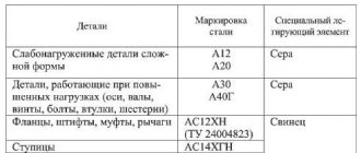
What is a pin
A mechanical pin is a metal part of a cylindrical or conical shape. They are made from carbon and alloy steels. Depending on the requirements, connections are made of metal that has been normalized or hardened. The connecting pin is made in the form of a cylinder or cone with a smooth polished surface. On cylindrical parts, longitudinal marks are made under the blind hole to allow air to escape.
Holes for the pins are drilled and countersinked simultaneously in both parts, fastened in working position. The surface roughness is no lower than class 5. Size allowance - interference fit is determined in accordance with GOST and is selected according to the material and its hardness. Depending on the connection to the shaft, bushing or part being driven in, the fit to the hole may be different.
In flat connectors, installation is made on a plane and two pins. In this case, the latch is attached to the blind hole of the main, massive part using an interference or tension fit. During assembly, the second fragment of the assembly is put on with holes onto fixed pins using a sliding or transitional fit. When disassembling the unit, it is enough to disconnect it along the plane, remove the smaller unit and pull the pins out of the base.
In connections that will be periodically disassembled for repairs or planned replacement of quickly wearing elements, a through hole is made in the walls of the parts being fastened.
The punches are inserted into the hole, they support the part being knocked out, and they hit the end with a hammer. The handle in the tool is an auxiliary element that serves for ease of use.
If it is structurally impossible to make a through hole, install a threaded pin inside or on the shank.
GOST 9464 for conical pins also provides other methods for removing parts. For example, conical products with a mushroom-shaped part protruding outward with a groove instead of a stem. A crowbar or wedge is inserted under the protrusion of the cap, and the latch is torn out of place and removed from the hole. For soft metal connections, square and hex socket drive shanks are used.
How to install and remove cotter pin fasteners
Despite the simplicity of the process, you should install the cotter pin yourself according to certain rules, taking into account the type and characteristics of the element. Standard and spring cotter pins can be inserted in two ways: parallel or perpendicular to the main axis of the main fastener.
The adjustable product is threaded through the hole intended for it and, at the exit, the ends are bent in opposite directions to secure it. The straight end of the needle pin must be inserted into the installation hole of the axle or shaft with a bend, the wavy part is pressed against the part being fastened from the outside. A spring effect is created.
Typical types of cotter pins are usually used once. The exception is ring products; they belong to the group of reusable hardware. When disassembling the fastener, it can be removed in two ways: knocking it out or drilling it out. First you need to try to straighten the bent ends or break them off. If the product cannot be removed, then it is knocked out from the reverse side with a hammer and chisel. In difficult cases, a drilling tool is used.
CONTROL AND TEST METHODS
4.1. The appearance of the cotter pins should be checked by inspection without the use of magnifying devices.
4.2. The dimensions of the cotter pins must be controlled by limit gauges or a universal measuring tool that provides the required measurement accuracy.
4.3. The diameter of the cotter pin must be controlled on the finished product in two mutually perpendicular planes.
4.4. When measuring the length of the cotter pin, the device shown in Fig. 2.
Crap. 2
45 Cotter pins with a nominal diameter of up to 5 mm must withstand at least 3 bends without signs of breakage or cracks; cotter pins with a nominal diameter of over 5 mm - at least 2 bends.
To test the bend, a pre-set cotter pin is clamped vertically in the jaws of a parallel vice (Fig. 3) so that the bend falls on the straight section of the cotter pin branch.
The edges of the jaws must have the radius of curvature indicated in Table 4.
The end of the cotter pin is bent 90°, and after returning the bent end to its original position, the bend is made in the same direction.
Crap. 3
Table 4
mm
| Nominal diameter of cotter pin d | Radius of rounding of the edges of the vice jaws R | |
| Nom. | Prev. off | |
| Up to 2 | 0,5 | +0,1 |
| St. 2 » 5 | 0,8 | |
| » 5 | 1,2 |
Each movement of the bent end by 90° is counted as one bend. The test is carried out at a speed of no more than one bend per second.
(Changed edition, Amendment No. 4).
4.5a. Methods for checking the quality and thickness of coatings - according to GOST 9.302-88.
(Introduced additionally, Amendment No. 4).
CONTROL AND TEST METHODS
4.1. The appearance of the cotter pins should be checked by inspection without the use of magnifying devices.
4.2. The dimensions of the cotter pins must be controlled by limit gauges or a universal measuring tool that provides the required measurement accuracy.
4.3. The diameter of the cotter pin must be controlled on the finished product in two mutually perpendicular planes.
4.4. When measuring the length of the cotter pin, the device shown in Figure 2 should be used.
4.5. Cotter pins with a nominal diameter of up to 5 mm must withstand at least 3 bends without signs of breakage or cracks; cotter pins with a nominal diameter of over 5 mm - at least 2 bends.
To test the bend, a pre-set cotter pin is clamped vertically in the jaws of a parallel vice (Fig. 3) so that the bend falls on the straight section of the cotter pin branch.
The edges of the jaws must have a radius of curvature indicated in Table 4.
source