Hydraulic cylinders are distinguished by high efficiency (0.96...0.98), extreme simplicity and compactness, which makes it possible to integrate them into a wide variety of machines and equipment. It can be said that the only drawback of hydraulic cylinders is the lack of adjustable versions.
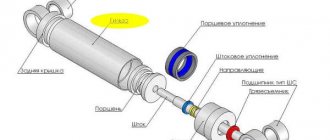
The main parts and assemblies of a typical cylinder (Fig. 1): liner 11, welded to the rear cover 12; piston 8 with support-sealing ring 10 and stopper 9; eye 1 with spherical bearing; axle box 4; rod 2 with support 5 and sealing 6 rings and a wiper 3. The working fluid is supplied to the rod and piston chambers through threaded holes 7.
Figure 1 – Typical hydraulic cylinder
The classification of hydraulic cylinders is based on the following characteristics (Fig. 2):
- direction of action of the working medium - single-acting (e), the output link of which is driven by the pressure of the working agent in only one direction, and the return of the rod is provided by an external force: spring, gravity, etc.; double-acting (a), in which the output link is capable of moving along the axis in mutually opposite directions;
- design of the working chamber - piston cylinders (a), in which the cavities are formed by a body and a piston with a rod; plunger (e), in which the cavity is formed by a body and a plunger; telescopic (h) have several rods extending from each other;
Figure 2 – Diagrams of hydraulic cylinders
- number of rods - single-sided (a) or double-sided (b) rod;
- method of supplying working fluid - a channel in the sleeve or in the rod (c);
- method of fastening - paws (i), flanges (k), lugs (l), trunnions (m) with threads on the rod, embedded half-rings (n) or welding of the back cover (it should be remembered that performing welding work near the final processed sleeve may cause deformation);
— presence of braking – double-acting hydraulic cylinders are equipped with a damper device that brakes the output link at the end of the stroke;
— conditions of use — drive of lever mechanisms; cyclically repeating useful work; movement of working bodies; useful work in motion; bringing the working body into a given position, ensuring the stability of the machine position;
— hydraulic cylinders are manufactured for moderate (U1), cold (HL1), dry (TC1) and humid (TV1) tropical climates.
Types of hydraulic cylinders
Depending on the design, there are several types of hydraulic cylinders.
- By number of rod positions
- Two-position
- Multi-position
- By the nature of the move
- Single stage
- Telescopic
- In the direction of action of the working fluid
- Single acting
- Double acting
- If possible, braking
- With braking
- No braking
- By type of worker
- Plunger
- Membrane
- Bellows
- Piston With one-way rod
- With double-sided rod
FEATURES OF POWER HYDRAULIC CYLINDERS
Let us note the features characteristic of power hydraulic cylinders
1) hydraulic cylinders are capable of functioning as a hydraulic motor and as a hydraulic pump;
2) high tightness of the device;
3) and efficiency close to 100%;
4) smooth stroke of the rod;
5) low noise level;
6) long service life;
7) high operational reliability.
Currently, a number of manufacturers are offering new approaches to the production of cylinders.
The new process produces cylinders from seamless, cold-drawn, honed or polished tubing and chrome-plated rods with final-machined running surfaces, which opens the door to high-quality, custom-designed cylinders with minimal labor costs. Apparently, this is the only example in drive technology. In any case, the facts of similar design of electric motors are unknown.
Double-acting hydraulic cylinder design
Double-acting hydraulic cylinders have two separated sealed working cavities into which liquid is supplied through different pipelines. Double-acting hydraulic cylinders can transmit the developed force in both forward and reverse directions.
Let's consider the design of a double-acting hydraulic cylinder using the example of the most common design with a one-sided rod.
Hydraulic cylinder with one-way rod
The main structural elements of a double-sided hydraulic cylinder with a one-sided rod are shown in the figure.
- stock
- front cover
- sleeve
- piston
- screw
- back cover
- wiper
- rod cuff
- rod guide ring
- piston cuff
- rubber ring
- piston guide ring
Operating principle of hydraulic cylinder
The working fluid from the pump is directed through the distributor into one of the cavities (piston or rod), the opposite cavity is connected to the drain.
When fluid enters the piston cavity, the hydraulic cylinder rod extends, if necessary, overcoming the load force. When working fluid enters the rod cavity, the hydraulic cylinder rod is retracted.
When fluid enters the piston cavity, the force developed by the hydraulic cylinder can be calculated using the formula:
When liquid enters the rod cavity, the effective area will change; the rod area must be subtracted from the piston area.
The tightness of the working chambers is ensured by lip seals, which do not allow fluid to flow from the piston cavity to the rod cavity. A cuff is also installed in the hydraulic cylinder cover to seal the rod, and a wiper to prevent contamination particles from entering the cylinder cavity.
Hydraulic cylinder with double-sided rod
The force and speed of movement of the piston with the rod during forward and reverse stroke will be different. If the same forces are required or the same speed of movement of the output links, then hydraulic cylinders with a double-sided rod are used.
In this type of hydraulic cylinder, one piston is connected to two rods.
To calculate the speed and force of a hydraulic cylinder with a double-sided rod, you can use the formulas:
In modern technology, hydraulic cylinder designs with a double-sided rod with a fixed cylinder and a fixed rod are used.
CHARACTERISTICS AND THEIR INFLUENCE
The main parameters of the hydraulic cylinder: nominal pressure pH, cylinder diameter D, diameter d and stroke L of the rod.
Diameters D and d determine the force that the hydraulic cylinder develops under a given pressure.
Let's consider the relationships between the main parameters of a cylinder with a one-sided rod (Fig. 4): areas A, cm2; diameters D and d, mm; forces F, N; pressure p, MPa; speeds v, m/min and flow rates Q, l/min.
Figure 4 – Main parameters of the hydraulic cylinder
Area of piston and rod cavities:
When the piston moves to the right, when piston chamber 1 is connected to the pressure line, and rod chamber 2 is connected to the drain line:
If the force F is expressed in kN, and the speed v in m/s, the power developed by the cylinder P = Fv, kW.
In hydraulic drives, the problem of obtaining different speeds of forward and reverse strokes (v1 < v2) often arises, which can be solved by using differential cylinders with different areas of working chambers. With a constant amount of working fluid entering the cylinder, the diameter of the rod
If, with a one-way rod, equality of movement speeds in both directions is required, differential activation of the cylinder with an area ratio of A1 = 2A2 is used. In this case, when the rod moves to the right, both chambers are connected to the pressure line (p1 = p2 = p), from which the flow rate Q of the working fluid comes. When moving to the left, the rod chamber is connected to the pressure line, and the piston chamber is connected to the drain line. For differential switching with negligible pressure losses in pipelines, the following relations are valid:
When the piston moves to the right, the rod is compressed by forces, under the influence of which longitudinal bending (loss of stability) can occur, and the determining factor here is the magnitude of the compressive force, the length and diameter of the rod, and the method of fixing the cylinder. To eliminate longitudinal bending, it is recommended to use a given stroke value s and, taking into account the maximum compressive force F1, to find the required diameter d of the rod.
Design of single-acting hydraulic cylinders
Single-acting hydraulic cylinders are capable of developing force in only one direction. The reverse stroke of such cylinders is carried out under the action of a spring, gravity, or external influence on the rod.
Plunger hydraulic cylinder
In hydraulic cylinders of this type, the liquid acts on a plunger located in the working chamber. The reverse stroke is carried out due to external forces or gravity.
The plunger is capable of transmitting only compression force; the magnitude of the force can be calculated using the relationship:
The speed of movement of the plunger will depend on the diameter of the plunger and the flow rate of the working fluid.
Spring return hydraulic cylinder
A spring return hydraulic cylinder is shown in the figure.
When the working fluid enters the piston cavity, a working stroke is carried out, the spring located in the rod cavity is compressed - the rod extends.
The reverse stroke is carried out due to the force of the spring, while the piston cavity is connected to the drain. The spring can be installed in both the piston and rod chambers.
Hydraulic cylinders of special design
Let's look at several special designs of hydraulic cylinders.
Telescopic hydraulic cylinders
In telescopic hydraulic cylinders, one rod is placed in the cavity of another rod. This makes it possible to obtain a large amount of movement of the output link with unchanged dimensions, since in telescopic cylinders the stroke can exceed the length of the sleeve.
Single-acting telescopic hydraulic cylinder
The working fluid is supplied to the cylinder cavity through the rear cover. The sections are pulled out sequentially - first, the section with the largest effective area will begin to move, then the one with the smaller one. The speed when extending each subsequent section will increase, and the force will decrease, due to a decrease in the effective area. For this reason, the force on the section with the minimum effective area should be calculated.
The reverse stroke is carried out under the influence of external forces, while the working cavity is connected to the drain.
Double-acting telescopic hydraulic cylinder
The supply of working fluid in the design shown in the figure is carried out through the rod.
The sections are extended in the same order as in single-acting telescopic hydraulic cylinders.
The return stroke is ensured by the supply of working fluid to the rod cavity, while the piston cavity is connected to the drain.
Combined hydraulic cylinders
To increase the force on the hydraulic cylinder rod, in the absence of the possibility of increasing the outer diameter, tandem or sequentially installed hydraulic cylinders are used. The diagram of a double hydraulic cylinder is shown in the figure.
In this case, an increase in force is achieved by adding a second working chamber and an additional piston, which allows the effective area of the hydraulic cylinder to be increased.
What types of hydraulic cylinders are there?
Depending on the design, there are several types of hydraulic cylinders.
By number of rod positions:
- Two-position
- Multi-position
According to the nature of the move:
- Single stage
- Telescopic
In the direction of action of the working fluid:
- Single acting
- Double acting
When braking is possible:
- With braking
- No braking
By type of worker:
- Plunger
- Membrane
- Bellows
- Piston: Single-rod
- With double-sided rod
Hydraulic cylinder with one-way rod
The main structural elements of a double-sided hydraulic cylinder with a one-sided rod are shown in the figure:
1. rod 2. front cover 3. liner 4. piston 5. nut 6. rear cover 7. wiper 8. rod seal 9. rod guide ring 10. piston seal 11. rubber ring 12. piston guide ring
The working fluid from the pump is directed through the distributor into one of the cavities (piston or rod), the opposite cavity is connected to the drain.
When fluid enters the piston cavity, the hydraulic cylinder rod extends, if necessary, overcoming the load force.
When working fluid enters the rod cavity, the hydraulic cylinder rod is retracted.
The tightness of the working chambers is ensured by lip seals, which do not allow fluid to flow from the piston cavity to the rod cavity. A cuff is also installed in the hydraulic cylinder cover to seal the rod, and a wiper to prevent contamination particles from entering the cylinder cavity.
Hydraulic cylinder with double-sided rod
The force and speed of movement of the piston with the rod during forward and reverse stroke will be different. If the same forces are required or the same speed of movement of the output links, then hydraulic cylinders with a double-sided rod are used.
In this type of hydraulic cylinder, one piston is connected to two rods.
Design of single-acting hydraulic cylinders
Single-acting hydraulic cylinders are capable of developing force in only one direction. The reverse stroke of such cylinders is carried out under the action of a spring, gravity, or external influence on the rod.
Plunger hydraulic cylinder
In hydraulic cylinders of this type, the liquid acts on a plunger located in the working chamber. The reverse stroke is carried out due to external forces or gravity.
Spring return hydraulic cylinder
When the working fluid enters the piston cavity, a working stroke is carried out, the spring located in the rod cavity is compressed - the rod extends. The reverse stroke is carried out due to the force of the spring, while the piston cavity is connected to the drain. The spring can be installed in both the piston and rod chambers.
Telescopic hydraulic cylinders
In telescopic hydraulic cylinders, one rod is placed in the cavity of another rod. This makes it possible to obtain a large amount of movement of the output link with unchanged dimensions, since in telescopic cylinders the stroke can exceed the length of the sleeve.
Single-acting telescopic hydraulic cylinder
The working fluid is supplied to the cylinder cavity through the rear cover. The sections are pulled out sequentially - first, the section with the largest effective area will begin to move, then the one with the smaller one. The speed when extending each subsequent section will increase, and the force will decrease, due to a decrease in the effective area. For this reason, the force on the section with the minimum effective area should be calculated.
The reverse stroke is carried out under the influence of external forces, while the working cavity is connected to the drain.
Double-acting telescopic hydraulic cylinder
The supply of working fluid in the design shown in the figure is carried out through the rod. The sections are extended in the same order as in single-acting telescopic hydraulic cylinders. The return stroke is ensured by the supply of working fluid to the rod cavity, while the piston cavity is connected to the drain.
Combined hydraulic cylinders
To increase the force on the hydraulic cylinder rod, in the absence of the possibility of increasing the outer diameter, tandem or sequentially installed hydraulic cylinders are used. The diagram of a double hydraulic cylinder is shown in the figure.
In this case, an increase in force is achieved by adding a second working chamber and an additional piston, which allows the effective area of the hydraulic cylinder to be increased.
Characteristics of hydraulic cylinders
The main parameters of hydraulic cylinders can be divided into several groups.
Geometric parameters
The diameter of the piston (liner), sometimes called the diameter of the hydraulic cylinder, the most common diameters are: 10, 12, 16, 20, 25, 28, 30, 32, 35, 38, 40, 45, 50, 55, 60, 63, 65 , 70, 75, 80, 85, 90, 95, 100 millimeters, etc. multiple of 5mm.
Rod diameter, the following hydraulic cylinder rod diameters are standardized: 4, 5, 6, 8, 10, 12, 16, 20, 25, 32, 40, 50, 63, 80, 100, 125, 160, 200, 250, 320, 400, 500, 630, 800 millimeters.
Stroke - the maximum possible movement of a piston with a rod or a hydraulic cylinder plunger
Hydraulic parameters
Nominal operating pressure is the pressure at which the hydraulic cylinder will operate in the nominal, design mode, while maintaining the operating and reliability parameters guaranteed by the manufacturer. The amount of pressure in the hydraulic cylinder is determined by the load value, and it can be limited by the settings of the safety or pressure relief valve. When there is no load, the pressure in the cylinder is caused only by friction losses.
Fluid flow entering the hydraulic cylinder.
Mechanical parameters
The force developed by a hydraulic cylinder is proportional to the pressure and the effective area affected by the fluid.
The speed of movement of the rod is determined by the amount of fluid flow entering the hydraulic cylinder and its effective diameter, as well as the diameter of the oil supply holes.
Typical hydraulic cylinder designs
Despite the huge variety of designs of hydraulic cylinders, there are typical solutions used in the design of hydraulic cylinders; we will consider some of them.
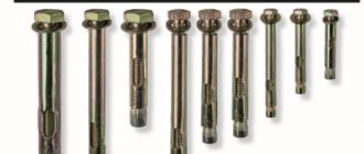
Hydraulic cylinder on studs
The front and rear covers of hydraulic cylinders of this design are connected by pins (anchors), the sleeve is sandwiched between the cylinder covers. The piston is sealed by two cuffs.
Round hydraulic cylinder
In the presented design, the covers are attached to round flanges secured by welding or threading to the sleeve. The type of piston seal shown in the illustration provides sealing in both directions.
Welded hydraulic cylinder
The covers are welded to the sleeve, the structure is non-separable and cannot be repaired. The cylinder has compact piston seals.
Hydraulic cylinder drawing
Design documentation for a hydraulic cylinder must include:
- assembly drawing of a hydraulic cylinder,
- specification,
- working drawings of parts.
As an example of the design of a hydraulic cylinder, we suggest that you familiarize yourself with the assembly drawing of a single-rod double-acting hydraulic cylinder. The front cover of this cylinder has a threaded connection with the liner, the rear cover with an eye is welded to the liner. The piston is fixed to the rod using threaded bushings, secured against rotation using a pin.
To download a hydraulic cylinder drawing in pdf format, click on the image.
You can also download the hydraulic cylinder drawing in dwg format.
Components
The hydraulic cylinder consists of the following parts:
The chambers in the hydraulic cylinder must be sealed. To achieve this goal, special seals are installed on the piston - cuffs that prevent fluid from flowing through the piston. Also, the cuffs are placed on the axle box, here they act as seals. The axle box is also equipped with a wiper to prevent particles from the external environment of the device from getting into the inside of the cylinder.
Important: The seals on the piston do not work if there are roughness and scratches inside the liner. The inside of the liner is ground by special machines at the factory to achieve a relatively perfectly smooth state.
Main characteristics
- Nominal pressure of working fluid
- Piston diameter size
- Rod diameter size
- Stroke value
The main characteristic of any hydraulic cylinder can be called the nominal pressure, since the number of hours that a given cylinder will work directly depends on the load placed on the cylinder.
The main criterion for the type division of hydraulic cylinders is their operating principle. There are five main types of hydraulic cylinders:
- Single acting
- Double acting
- Telescopic
Single-acting hydraulic cylinders.
When pressure builds up in the working chamber, the rod extends. The return of the rod in this type of device occurs by means of a spring installed inside, or due to the gravity of the lifted load. It is also possible to return the rod using another hydraulic drive. The operation of the single-acting unit is similar to the operation of a jack.
Double-acting hydraulic cylinders.
The design of such devices provides that the working fluid is located in the rod and piston chambers. The rod moves forward and backward due to the pressure of the working fluid. During operation, it is pumped into one of the working chambers and merges with the other, due to which it is possible to control the movement of the rod in both directions.
Based on the type of connection, double-acting hydraulic cylinders are divided into 2 types:
- Easy connection. The rod and piston working chambers are connected alternately to the injection and drain hydraulic lines, which respectively pump and drain the hydraulic fluid. All displaced fluid is drained into the hydraulic tank.
- Differential connection. Otherwise called a ring connection. In this case, the liquid that leaves the rod chamber is directly pumped into the piston chamber.
Telescopic hydraulic cylinders.
A device of this type allows for a large stroke of the rod with small dimensions. This is achieved by the fact that it consists of several cylinders placed in each other’s cavity. There are single-acting and double-acting models on the market.
ANALYSIS OF COMPANIES MANUFACTURING POWER CYLINDERS
Many enterprises around the world are engaged in the production of hydraulic cylinders.
Let's name the most famous foreign companies that have been recognized for the high quality of their manufactured power hydraulic cylinders:
Atos, Bosch Rexroth, Duplomatic, Eaton Vickers, Parker.
Domestic enterprises have long and reliably secured their positions in the niche of creating hydraulic cylinders:
1) Omskgidroprivod - production of 16MPa hydraulic cylinders for mobile equipment and lower pressure for combine harvesters.
2) Yeletshydroagregat (Elets, Lipetsk region) - produces hydraulic cylinders for road construction, municipal, agricultural and logging equipment.
3) StroyDorMash (Oryol) – hydraulic cylinders 14, 16 and 21 MPa, spare parts and rubber products (rubber products) for hydraulic cylinders.
4) Gidrolast (St. Petersburg) – produces large batches of hydraulic cylinders and integrates manufactured hydraulic cylinders into final products.
5) Finaros (St. Petersburg) - telescopic GCs and hydraulic cylinders for hydraulic manipulators.
6) Artillery Plant No. 9 (Ekaterinburg) – hydraulic and pneumatic power cylinders of single- and double-acting up to 80 MPa, diameter up to 300 mm, length up to 4000 mm.
7) Aggregate plant (Lyudinovo, Kaluga region) - hydraulic drives, pumping stations, units and installations, pumps, hydraulic motor DP510I, pump NP 120, hydraulic cylinders GU80X50X710, SN75M-63X50X90, filters, high pressure hoses, hydraulic valves).
Main types of structures
To drive the working parts of mobile machines, double-acting piston hydraulic cylinders with a single-sided rod are most widely used (Fig. 3.15, 3.16, a
,
b).
The basis of the design (see Fig. 3.15) is sleeve 6,
which is a pipe with a carefully processed inner surface.
A piston 2 moves inside the liner,
having rubber lip seals
8,
which prevent fluid from flowing from the cylinder cavities separated by the piston.
The force from the piston is transmitted by the rod 13,
which has a polished surface.
To guide it, use the front through cover (axle box) 4.
On both sides of the liner there are covers with holes for supplying and discharging working fluid.
The seal between the rod and the cover 11
consists of two cuffs, one of which prevents fluid leakage from the cylinder, and the other serves as a wiper
12.
The eye 5 serves to movably secure the hydraulic cylinder. A part connecting the hydraulic cylinder to the moving mechanism is usually attached to the front part of the rod with an eye.
Rice. 3.15. Design of a typical piston hydraulic cylinder:
- 1 — lock nut; 2 -
piston;
3
- fitting;
4 —
front through cover (axlebox);
5 - eye; 6 —
cylinder liner;
7 — piston seal with guide elements; 8, 10 -
static seals;
9 —
support and guide rings;
11 —
rod seal;
12 —
wiper; - 13 — rod with eye
Rice. 3.16. Hydraulic cylinder with one-sided rod: a -
cross-sectional appearance;
b -
design
In Fig. 3.17, a, b, c
Typical designs of cylinders used in construction, track, loading and unloading and mining machines are presented.
The simplest type in design are single-acting hydraulic cylinders: plunger cylinders and cylinders with spring return (Fig. 3.18, 3.19).
Plunger hydraulic cylinders do not have a piston, and the force is transmitted directly by the plunger touching the cylinder at the sealing point (see Fig. 3.18).
Plunger cylinders are in most cases installed vertically and rest on the moving part of the machine. With that
= 16 MPa and p = 20 MPa for machines with light and medium operating modes"/>
Rice. 3.17. Typical designs of hydraulic cylinders at /nom = 16 MPa and mouth = 20 MPa for machines with light and medium operating conditions ( a)
at
pHQM
= 16 MPa and
mouths
= 20 MPa for earthmoving and transport machines and on mouths = 25-32 MPa for heavy-duty forestry machines
(b);
at rn = 32 MPa and
rt
= 40 MPa for single-bucket universal excavators of size groups III—VI
(c):
1
- eyelet;
2
— oiler;
3
— wiper;
4
- union nut;
5 — clamping bushing; 6—
pin;
7— chevron cuffs; 8—
bushings;
9—
ring;
10 -
bushing;
11 -
plug;
12
— rod;
13
— body;
14 —
damper bushing;
15 -
damper;
16 -
cuff;
17 —
protective ring;
18
—anti-friction coating;
19
— piston,
20
— cuff holder;
21
— sealing ring;
22
- nut;
23
— retaining ring;
24
— rear cover;
25
—
Rice. 3.18. Plunger hydraulic cylinder:
1 —
frame;
2 —
rod;
3 -
bushing;
4
- cuff;
5, 6 -
sealing rings;
7 - lock; 8 —
spacer;
9 —
spring ring;
10
— wiper
Rice. 3.19. Spring return hydraulic cylinder:
1 —
frame;
2, 3 —
seals;
4
- plunger;
5 - glass; 6
— rod;
7 - spring; 8
— bushing;
9 -
nut;
10 -
screw with spring;
11 —
plunger sleeve
Rice. 3.20. Hydraulic jack (outrigger) in its location, the working body rises due to the fluid pressure perceived by the plunger and cylinder, and lowers under the influence of the weight of the structure associated with the retractable part when connecting the cylinder cavity with a pipeline that discharges the working fluid into the tank.
A special type of hydraulic cylinders are the so-called hydraulic jacks, used as outriggers in transport and road construction machines. One of the options is shown in Fig. 3.20. A characteristic feature of such hydraulic cylinders is the small ratio of the piston diameter to the rod diameter.
Hydraulic cylinder - device, operating principle, force calculation
The performance of many types of power equipment, both industrial and domestic, is ensured by a device such as a hydraulic cylinder. Acting as a reciprocating drive motor, such a mechanism, with minimal energy consumption, ensures a full cycle of operation of power equipment used in construction, in various industries, in agricultural enterprises and in everyday life. Hydraulic cylinders are most widely used as the main element of equipment for pressing equipment, which is actively used to solve various problems.
A hydraulic cylinder is a volumetric hydraulic motor that converts the energy of fluid flow into mechanical energy
Design features and principle of operation
The design of any hydraulic cylinder includes the following elements:
Plunger hydraulic cylinders are somewhat different in design, in which the plunger simultaneously performs the functions of a piston and a rod.
Hydraulic cylinder diagram
The operating principle of any type of hydraulic cylinder is based on the pressure of the working fluid on the piston. As a result of the impact on the hydraulic cylinder piston, the rod begins to perform cyclic work, transmitting force to the working unit of the equipment served by the device. Such a working unit, the functioning of which is ensured by a hydraulic cylinder, depending on the type and purpose of the equipment, can be a compacting platform, a bending or pressing mechanism, as well as a device of any other type that ensures the transmission of the force of the hydraulic cylinder to the final recipient of power energy.
Sliding hydraulic cylinder device
Since the force created by a hydraulic cylinder, as mentioned above, is formed due to the pressure exerted by the working fluid on the piston, the properties of this fluid have a significant impact on the efficiency of use, technical and operational characteristics of the cylinder itself. As a working fluid for piston or plunger type hydraulic cylinders, as a rule, a special oil is used, which must meet certain requirements for a number of parameters:
- chemical composition and density;
- temperature values at which the working fluid retains its original characteristics;
- the tendency of the working fluid to develop oxidative processes.
To operate hydraulic cylinders of various types and models, working fluid is pumped into their internal chamber using a manual or electric pump.
CONSTRUCTION DIAGRAMS AND TYPICAL PERFORMANCE CHARACTERISTICS
The design diagrams of power hydraulic cylinders are shown in Fig. 5.
Figure 5 – Design diagrams of hydraulic cylinders:
piston with one-sided (a) and double-sided (b) rod; telescopic (in)
The main parameters of the cylinders are regulated by GOST 6540-68.
The following rows are installed:
nominal pressure р nom , MPa: 0.63; 1; 1.6; 2.5; 6.3; 10; 16; 20; 25; 32; 40; 50; 63;
piston diameter D , mm: 10; 12; 16; 20; 25; 32; (36); 40; (45); 50; (56); 63; (70); 80; (90); 100; (110); 125; (140); 160; (180); 200; (220); 250; (280); 320; (360); 400; (450); 500; (560); 630; (710); 800; (900);
rod diameter d , mm: 4; 5; 6; 8; 10; 12; (14); 16; (18); 20; (22); 25; (28); 32; (36); 40; (45); 50; (56); 63; (70); 80; (90); 100; (110); 125; (140); 160; (180); 200; (220); 250; (280); 320; (360); 400; (450); 500; (560); 630; (710); 800; (900);
piston (plunger) stroke s , mm: 4; 6; 8; 10; 12; 16; 20; 25; 32; 40; 50; (56); 63; (70); 80; (90); 100; (110); 125; (140); 160; (180); 200; (220); 250; (280); 320; (360); 400; (450); 500; (560); 630; (710); 800; (900); 1000; (1120); 1250; (1400); 1600; (1800); 2000; (2240); 2500; (2800); (3000); 3150; (3350); (3550); (3750); 4000; (4250); (4500); (4750); 5000; (5300); (5600); (6000); 6300; (6700); (7100); (7500); 8000; (8500); (9000); (9500).
In accordance with GOST 25020-84, connecting threads of rods and plungers should be selected from the following range: M3×0.35; M4×0.5; M5×0.5; M6×0.75; M8×1; M10×1.25; M12×1.25; M14×1.5; M16×1.5; M18×1.5; M20×1.5; M22×1.5; M24×2; M27×2; M30×2; M33×2; M36×2; M42×2; M48×2; M56×2; M64×3; M72×3; M80×3; M90×3; M100×3; M110×3; M125×4; M140×4; M160×4; M180×4; M200×4; M220×4; M250×6; M280x6.
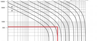
Depending on the purpose of the hydraulic cylinders, the pressures must correspond to those indicated in the table. 1.
The maximum speed of the rod relative to the hydraulic cylinder body is indicated in table. 2.
Table 1 Working fluid pressure
Table 2 Allowable rod speed
Main varieties
Different types of hydraulic cylinders are distinguished according to a number of parameters. So, depending on the number of positions that the device’s rod can occupy, it can be:
Depending on the nature of the stroke of the piston and rod, the following types of hydraulic cylinders are distinguished:
- single-stage devices;
- telescopic hydraulic cylinders.
Operating principle of various types of hydraulic cylinders
A single-acting telescopic device or a double-acting telescopic hydraulic cylinder is used in cases where it is necessary for the rod overhang to exceed the length of the hydraulic cylinder body. A telescopic hydraulic cylinder consists of several cylinders that are nested one inside the other, and the body of each subsequent cylinder is the rod of the previous one.
Depending on how many directions the working fluid of a hydraulic cylinder acts in, it can be:
- single-acting hydraulic cylinder;
- device with a double-sided rod.
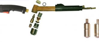
Hydraulic cylinders with double-sided rod TsG1 and TsG2, intended for installation work and rescue operations
The working fluid in single-acting hydraulic cylinders acts on the piston in only one direction. To perform a reverse action with a one-way rod, that is, to move it in the opposite direction, spring elements are used. The use of a return spring in the design of single-acting hydraulic cylinders results in the fact that they create less force than double-acting hydraulic cylinders, the pistons of which do not have to overcome the elastic force of the spring element.
The design of double-acting hydraulic cylinders is designed in such a way that the working fluid acts immediately on two opposite planes. One of the modifications of a double-acting hydraulic cylinder is a device equipped with two rods located on opposite sides of the piston. The connection diagram for a double-acting hydraulic cylinder provides that one part of its internal chamber is connected to the pressure line of the hydraulic system, and the second to the drain line.
Diagram of a double-acting hydraulic cylinder
When using a double-sided hydraulic cylinder equipped with a single rod, one should take into account the fact that such a device creates more force when the piston moves in the forward direction than when moving in the reverse direction. This is explained by the fact that the areas of the working planes of the piston on the side of the rod and on its reverse side differ, respectively, when the working fluid acts on these planes, pressure of different magnitudes is created.
The design of the hydraulic cylinder may include a special mechanism responsible for braking the rod. Depending on the presence or absence of such a mechanism in the design, hydraulic cylinders are divided into devices with and without braking.
Traditional hydraulic cylinder design with end-stroke braking
Hydraulic cylinders are divided into different types depending on the type of main working element used in their design. So, they distinguish:
- plunger hydraulic cylinder;
- a device that operates due to a membrane installed in it;
- bellows-type hydraulic cylinder;
- a piston-type hydraulic cylinder, which, as mentioned above, can be equipped with one or two working rods.
The design has a direct impact on the performance of hydraulic cylinders. This should be taken into account when selecting such devices to equip equipment for a specific purpose.
Hydraulic exhaust cylinder JTC, developing a force of 10 tons
Submit your application
Single acting hydraulic power cylinder
In a mechanism of this type, the movement of the rod occurs due to the pressure of the working fluid, which is supplied through special hoses: high-pressure hoses.
It returns back using the force of a spring. The force created by a one-way hydraulic cylinder is less than that created by a double-acting analogue under the same conditions. The difference is due to the fact that part of the hydraulic energy is distributed to cope with the spring stiffness force.
There is also a type of single-acting hydraulic power cylinder They are used in cases where the return of the rod is possible using the own weight of the lifted load, or the action of the device. Therefore, in this case, the use of a spring is inappropriate.
Hydraulic cylinders of this type can be plunger, telescopic, or piston.
Double acting hydraulic power cylinder
In these devices, the energy of the hydraulic fluid is used in two directions: during forward and reverse movement of the piston. During the forward stroke, more pressure is definitely created on the rod itself, provided that the speed of the rod movement is lower than during the reverse stroke. This is due to the fact that the areas where the pressure of the working fluid falls are different. For example, such power hydraulic cylinders perform lifting and lowering manipulations in many bulldozers.
Double-acting hydraulic cylinders come in four types:
- telescopic;
- with one-sided rod;
- with double-sided rod;
- combined.
Combined hydraulic cylinders
Combined hydraulic cylinders are used in cases where it is not possible to install a hydraulic motor with a larger diameter than it already has, but there are no restrictions on length. In such cases, several engines are used, where two or three hydraulic cylinders are connected in series to maintain traction or pushing force on the rod.
Multi-speed hydraulic cylinders
Multi-speed power hydraulic cylinders are used in conditions where it is necessary to work with different speed modes of piston operation. To do this, you need to connect a constant-capacity pump.
Rodless hydraulic cylinders
Rodless hydraulic power cylinders are mainly used in rotary clamping mechanisms (during the operation of the piston in steering machines, the transformation is first carried out into angular or rotary movement). In such cases, rodless hydraulic cylinders are an indispensable part of the entire mechanism.
LLC PTK "KRPMS" produces all types of power hydraulic cylinders to order. Contact us in a way convenient for you to clarify details or place an order.