Main characteristics
In most cases, chokes have significant dimensions. To make devices compact without compromising technical characteristics, the inductor is replaced with a stabilizer, which is essentially a powerful transistor. The result is an electronic throttle. However, a device of this type is a semiconductor, so it is not practical to use it in high-frequency devices.
The electronic choke must be selected according to several parameters, the main one of which is inductance, measured in H. Also important technical characteristics of the devices are:
resistance, which is taken into account with direct current; voltage change within acceptable limits; bias current – the nominal value is used.
When choosing a device, first of all you need to focus on goals and objectives, for which you need a choke in electrical circuit diagrams. The use of magnetic cores in electric chokes makes it possible to ensure compactness of the devices while maintaining the same inductance values. Ferrite and magnetodielectric compounds, due to their low capacitance, can be used in wide frequency ranges.
Table of electrical parameters of chokes D101…D179
| Throttle type | Core | Inductance at nom. current, Gn | Rated current A | Winding resistance, Ohm |
| D101 | ШЛ6 x 6.5 | 0,01 | 0,40 | 1,7 |
| D102 | ШЛ6 x 6.5 | 0,02 | 0,28 | 3,17 |
| D103 | ШЛ6 x 6.5 | 0,04 | 0,2 | 5,90 |
| D104 | ШЛ6 x 8 | 0,005 | 0,8 | 1,02 |
| D105 | ШЛ6 x 8 | 0,01 | 0,56 | 1,77 |
| D106 | ШЛ6 x 8 | 0,02 | 0,4 | 3,70 |
| D107 | ШЛ6 x 8 | 0,04 | 0,28 | 8,20 |
| D108 | ШЛ6 x 8 | 0,08 | 0,2 | 15,3 |
| D109 | ШЛ8 x 8 | 0,0025 | 1,6 | 0,30 |
| D110 | ШЛ8 x 8 | 0,005 | 1,1 | 0,52 |
| D111 | ШЛ8 x 8 | 0,01 | 0,8 | 1,32 |
| D112 | ШЛ8 x 8 | 0,02 | 0,56 | 2,37 |
| D113 | ШЛ8 x 8 | 0,04 | 0,4 | 5,9 |
| D114 | ШЛ8 x 8 | 0,08 | 0,28 | 12,3 |
| D115 | ШЛ8 x 8 | 0,16 | 0,2 | 21,9 |
| D116 | ШЛ8 x 12.5 | 0,0012 | 3,2 | 0,115 |
| D117 | ШЛ8 x 12.5 | 0,0025 | 2,2 | 0,234 |
| D118 | ШЛ8 x 12.5 | 0,005 | 1,6 | 0,484 |
| D119 | ШЛ8 x 12.5 | 0,01 | 1,1 | 0,825 |
| D120 | ШЛ8 x 12.5 | 0,02 | 0,8 | 2,00 |
| D121 | ШЛ8 x 12.5 | 0,04 | 0,56 | 3,80 |
| D122 | ШЛ8 x 12.5 | 0,08 | 0,4 | 8,15 |
| D123 | ШЛ8 x 12.5 | 0,16 | 0,28 | 14,16 |
| D124 | ШЛ10 x 12.5 | 0,32 | 0,2 | 17,8 |
| D125 | ШЛ10 x 12.5 | 0,0006 | 6,3 | 0,04 |
| D126 | ШЛ10 x 12.5 | 0,0012 | 4,3 | 0,083 |
| D127 | ШЛ10 x 12.5 | 0,0025 | 3,2 | 0,179 |
| D128 | ШЛ10 x 12.5 | 0,005 | 2,2 | 0,386 |
| D129 | ШЛ10 x 12.5 | 0,01 | 1,6 | 0,643 |
| D130 | ШЛ10 x 12.5 | 0,02 | 1,1 | 1,57 |
| D131 | ШЛ10 x 12.5 | 0,04 | 0,8 | 2,78 |
| D132 | ШЛ10 x 12.5 | 0,08 | 0,56 | 5,63 |
| D133 | ШЛ10 x 20 | 0,16 | 0,4 | 6,60 |
| D134 | ШЛ10 x 20 | 0,32 | 0,28 | 13,4 |
| D135 | ШЛ10 x 20 | 0,65 | 0,2 | 28,7 |
| D136 | ШЛ10 x 20 | 0,0003 | 12,5 | 0,012 |
| D137 | ШЛ10 x 20 | 0,0006 | 9,0 | 0,032 |
| D138 | ШЛ10 x 20 | 0,0012 | 6,3 | 0,07 |
| D139 | ШЛ10 x 20.5 | 0,0025 | 4,5 | 0,152 |
| D140 | ШЛ10 x 20.5 | 0,005 | 3,2 | 0,284 |
| D141 | ШЛ10 x 20.5 | 0,01 | 2,2 | 0,54 |
| D142 | ШЛ10 x 20.5 | 0,02 | 1,6 | 1,20 |
| D143 | ШЛ10 x 20 | 0,04 | 1,1 | 2,26 |
| D144 | ШЛ12 x 25 | 0,02 | 0,8 | 2,14 |
| D145 | ШЛ12 x 25 | 0,16 | 0,56 | 4,09 |
| D146 | ШЛ12 x 25 | 0,32 | 0,4 | 8,20 |
| D147 | ШЛ12 x 25 | 0,65 | 0,28 | 19,2 |
| D148 | ШЛ12 x 25 | 1,3 | 0,2 | 34,5 |
| D149 | ШЛ12 x 25 | 0,00015 | 25,0 | 0,0024 |
| D150 | ШЛ12 x 25 | 0,0003 | 18,0 | 0,0075 |
| D151 | ШЛ12 x 25 | 0,0006 | 12,5 | 0,017 |
| D152 | ШЛ12 x 25 | 0,0012 | 9,0 | 0,038 |
| D153 | ШЛ12 x 25 | 0,0025 | 6,3 | 0,096 |
| D154 | ШЛ12 x 25 | 0,005 | 4,5 | 0,184 |
| D155 | ШЛ12 x 25 | 0,01 | 3,2 | 0,338 |
| D156 | ШЛ12 x 25 | 0,02 | 2,2 | 0,715 |
| D157 | ShLM20 x 25 | 0,04 | 1,6 | 0,68 |
| D158 | ShLM20 x 25 | 0,08 | 1,1 | 1,35 |
| D159 | ShLM20 x 25 | 0,16 | 0,8 | 2,85 |
| D160 | ShLM20 x 25 | 0,32 | 0,56 | 6,15 |
| D161 | ShLM20 x 25 | 0,65 | 0,4 | 11,9 |
| D162 | ShLM25 x 25 | 1,3 | 0,28 | 22,4 |
| D163 | ShLM25 x 25 | 0,0003 | 25 | 0,0053 |
| D164 | ShLM25 x 25 | 0,0006 | 18 | 0,01 |
| D165 | ShLM25 x 25 | 0,0012 | 12,5 | 0,212 |
| D166 | ShLM25 x 25 | 0,0025 | 9 | 0,05 |
| D167 | ShLM25 x 25 | 0,005 | 6,3 | 0,12 |
| D168 | ShLM25 x 25 | 0,01 | 4,5 | 0,26 |
| D169 | ShLM25 x 25 | 0,02 | 3,2 | 0,5 |
| D170 | ShLM25 x 25 | 0,04 | 2,2 | 0,28 |
| D171 | ShLM25 x 25 | 0,08 | 1,6 | 1,02 |
| D172 | ShLM25 x 25 | 0,16 | 1,1 | 1,94 |
| D173 | ShLM25 x 25 | 0,32 | 0,8 | 4,52 |
| D174 | ShLM25 x 25 | 0,65 | 0,56 | 8,50 |
| D175 | ShLM25 x 25 | 0,0006 | 25 | 0,0075 |
| D176 | ShLM25 x 25 | 0,0012 | 18 | 0,02 |
| D177 | ShLM25 x 25 | 0,0025 | 12,5 | 0,053 |
| D178 | ShLM25 x 25 | 0,005 | 9 | 0,085 |
| D179 | ShLM12 x 25 | 0,01 | 6,3 | 1,48 |
Below is a table of electrical parameters of chokes types D201T - D274T.
The table shows the parameters of the chokes when the windings are connected in parallel.
When the windings are connected in series, the inductance and resistance of the final winding will be four
times greater, the bias current will be halved
and
the maximum value of the alternating voltage will be
doubled
.
Figure 2. Diagram of windings of chokes D201T-D274T.
Self-production
To make your own throttle, you need to correctly calculate its design. To do this, use a simple formula for calculating inductance: L=0.01*d*w 2 /(L/d+0.44), where d is the diameter of the base (cm), L is the length of the wire (cm), w is the number of turns . Moreover, if you have a multimeter with the ability to change the inductance, then the exact number of turns can be selected using it.
The winding method using this formula involves laying turn to turn. For example, it is necessary to select a magnetic circuit for a choke with an inductance of one μH, designed for a current I = 4A. A 2000 NM core of standard size K 16 x 8 x 6 is taken. According to the reference book, the initial inductance coefficient is ALH = 1.36 μH, and the magnetic path length is le = 34.84 mm. Accordingly, the number of turns will be N= (L/ALH)0.5= (1/1.36)0.5 = 0.86. If we take N=1, then at a given current the magnetic field strength in the core will be equal to H= 4*1/(34.84*10−3)= 114 A/m.
Thus, the inductor is a coil characterized by inductance. Thanks to its properties, it can accumulate magnetic power and then release it into the circuit in the form of electrical energy. Moreover, the use of the element also makes it possible to suppress the alternating current component in the circuit.
A choke (translated from German as “reduce”) is a type of inductor. The main purpose of this element of the electrical circuit is to “delay” (reduce for a certain period of time) the influence of currents of a certain frequency range. At the same time, it is almost impossible to sharply change the current strength in the coil - here the law of self-induction comes into force, due to which additional voltage is formed at the output.
A choke is needed in an electrical circuit when it is necessary to suppress the alternating component of the current (for example, noise), significantly reduce ripple in the network, and also limit or separate various frequency signals in accordance with the task (isolation or decoupling).
In electrical and radio engineering, alternating current is used in the range from units to hundreds of billions of Hz. (1 hertz is one oscillation per second).
Conventionally, such wide boundaries are divided into several sections:
- low (audio) frequencies (20 Hz – 20 kHz);
- ultrasonic frequencies (20 – 100 kHz);
- high and ultra-high frequencies (from 100 kHz and above).
The latter consists of turns of insulated wire wound onto a steel core made of insulated plates (to avoid the occurrence of Foucault currents), and has high inductance. Such a coil is characterized by strong resistance to any changes in current in the circuit: it supports it when it decreases, and restrains it when it sharply increases.
Also, chokes are widely used in the implementation of various high-frequency electrical circuits. In this case, their design can be single or multilayer, while cores (both steel and ferromagnetic) are often not used. Sometimes ordinary resistors or plastic frames are used as the basis for winding. In the range of long and medium waves, special sectional wire winding is also used to ensure the specified parameters.
The latter indicator is widely used in calculations of oscillatory circuits.
The use of magnetic cores makes it possible to significantly reduce the dimensions of chokes with the same declared inductance parameters. At high frequencies, ferrite and magnetodielectric compounds are used, which, due to their small intrinsic capacitance, allow them to be used over a wide range.
According to their purpose, this type of inductor can be divided into the following types:
- alternating current. Used for current limiting in the network; for example, during the start of an electric motor or pulsed PVEP.
- saturation. The main area of application is voltage stabilizers.
- smoothing. Designed to weaken ripples of already rectified current.
- magnetic amplifiers (MU). They are inductor coils, the core of which is magnetized by direct current. By changing the parameters of the latter, you can change the inductive reactance.
Three-phase chokes are also available for use in appropriate circuits.
Today, various types of chokes are widely used to solve a variety of engineering problems.
Watch an interesting video about electric throttles below:
Basic concepts in electronics
The English physicist William Gilbert is considered the founder of the discovery of electricity. In 1600, he introduced the concept of “amber”, which means electricity. Scientists discovered through experiments with amber that if it is rubbed against silk, it acquires the properties of attracting other physical bodies to itself. This is how static electricity was discovered. The first electric car was created by the German engineer Otto von Guericke. The unit looked like a metal pole with a sulfur ball placed on its top.
In subsequent years, a number of physicists and engineers from various countries explored the properties of electricity, discovering new phenomena and inventing instruments. The most outstanding scientists who made significant contributions to science are Galvani, Volt, Estred, Ohm, Faraday, Hertz, Ampere. Recognizing the importance of their discoveries, fundamental quantities characterizing various electrical phenomena were named after them.
The result of their experiments and theoretical guesses was the work of Maxwell, who created the theory of electromagnetic phenomena in 1873. And twenty years later, the Englishman Thomson discovered a particle involved in the formation of electricity (electron), the position of which in the atomic structure of the body was later indicated by Rutherford.
Thus, it was discovered that electric charge is the ability of physical bodies to create a special field around themselves that affects other substances. Electricity is associated with magnetism, which affects the position of electrons, which are the elementary particles of the body. Each such particle has a certain energy (potential) and can move around the body randomly.
Giving electrons directional movement leads to the generation of current. The work spent on moving an elementary particle is called stress. If current flows in a closed circuit, then it creates a magnetic field, that is, a force acting on electrons.
All substances are divided into three types:
- conductors are bodies that freely pass current through themselves;
- dielectrics - the appearance of free electrons in these bodies is impossible, which means that current cannot flow through them;
- semiconductors are materials whose ability to transmit current depends on external factors, such as temperature.
The characteristic indicating the ability of a body to conduct current is called conductivity, and its inverse value is called resistance.
Active resistance
The passage of electric current is ultimately influenced by three physical quantities: resistance, inductance and capacitance. Each radio element (the choke is no exception) possesses them to some extent.
Active resistance is a value that prevents the passage of current and is equal to the ratio of the potential difference to the current strength (Ohm's law). Its essence is explained by the fact that the crystal lattice of different physical bodies contains a different number of free charge carriers. In addition, the structure itself may be heterogeneous, that is, contain impurities or defects. Electrons, moving under the influence of the field, collide with them and give part of their energy to the crystals of the body.
As a result of such collisions, the particles lose momentum and the current strength decreases. The dissipated electrical energy is converted into heat. An element that uses the natural properties of a physical body is a resistor.
As for the inductor, its active resistance is considered parasitic, causing heating and deterioration of parameters. It depends on the type of material and its physical dimensions.
Determined by the formula R = p * L / S, Ohm, where:
- p—resistivity (reference value), Ohm*cm;
- L—conductor length, cm;
- S—cross-sectional area, cm2.
Capacitive component
Any current conductor has the ability to accumulate electrical charge to varying degrees. This ability is called element capacity. For some radio components it is considered a harmful component (in particular, for the inductor), while for others it is considered useful (capacitor). This concept is referred to as reactance. Its value depends on the type of signal supplied to the element and the capacity of the material from which it is made.
You will be interested in the history of the creation of electricity, its types and applications in science and life
Mathematically, reactance is described by the expression Xc = 1/w*C, where:
- w is the cyclic frequency, a scalar angular value determined by the number of signal oscillations per unit time (2*p*f), Hz;
- C—element capacity, F.
From the formula it is clear that the greater the capacitance and frequency of the current, the higher the resistance of the element, which means that the inductor, which has a large capacitive reactance, will heat up. The value of the capacitance in the inductor depends on the size of the conductor and the method of its installation. With spiral winding, a capacitance appears between adjacent rings, which also affects the flowing current.
The parasitic component of the capacitance also manifests itself in the formation of the product’s own resonance, since the inductor in the equivalent circuit can be represented as a series chain of inductance and capacitor. This inclusion creates an oscillatory circuit operating at a certain frequency. If the signal frequency is below the resonant value, then the inductive component will dominate, and if higher, the capacitive component will dominate.
Therefore, an essential task of manufacturing a choke in electronics is considered to be to increase the structure’s own resonance.
Inductance and self-induction
The electric field is inextricably linked with the magnetic field. Where one exists, the second invariably appears. Inductance is a physical quantity characterized by the accumulation of energy, but unlike capacitance, this energy is magnetic. Its value depends on the magnetic flux formed by the strength of the current flowing through the radio element. The higher the current, the stronger the magnetic flux penetrates the product. The intensity of energy accumulation by an element depends on this flow.
The mathematical formula for finding inductance is L = Ф/ I, where:
- F—magnetic flux, Wb;
- I is the current flowing through the element, A.
Inductance is measured in henry (H). Thus, the inductor at the moment of current flowing through it creates a magnetic flux equal to one weber (Wb).
The resistance provided by inductance depends largely on the frequency of the applied signal. To calculate it, use the expression XL = w*L. That is, for direct current it is zero, and for alternating current it depends on its frequency. In other words, for a high-frequency signal the element will have high resistance.
The physical process observed when alternating current passes through inductance can be described as follows: during the first decade of the signal (the current increases), the magnetic field intensively consumes energy from the electrical circuit, and in the last decade (the current decreases) it gives it back, so during the period of passage current no power is consumed.
But this model fits an ideal element; in fact, some of the energy is converted into heat. That is, losses occur, characterized by the quality factor Q, determined by the ratio of the received energy to the transmitted one.
When the current flowing through a conductor in a circuit changes, an electromotive force of induction (EDSI) occurs - self-induction. In other words, alternating current changes the magnitude of the magnetic flux, which ultimately leads to the appearance of EDSI. This effect manifests itself in slowing down the processes of current appearance and decay. The amplitude of self-induction is proportional to the magnitude of the current, the frequency of the signal and the inductance. Its phase lag from the signal is 90 degrees.
Marking of small devices
Devices for electronic boards have dimensions of no more than 2-3 cm. It is almost impossible to apply readable markings in digital or letter designations. For this purpose, color coding of electronic chokes is used. Chokes in the diagrams are depicted in the form of a spiral with a parallel line.
Several colored rings are applied to the cylindrical body of the radio component. The first two bars (from left to right) indicate the inductance value, measured in mHenry. The third bar indicates the multiplier by which the inductance number should be multiplied. The fourth ring expresses the permissible deviation in % from the nominal value. If it is not on the body of the part, then the tolerance is considered to be within 20%.
Color coding table
For example, the colors of the rings are in the following order: brown, yellow, orange and silver. This means an inductance value of 14 mH, where the deviation tolerance is 10%.
Technological progress does not stand still. Every year new analogues of outdated models appear. The development of new technologies in all areas of human activity requires the improvement of radio components, including chokes.
Markings and symbols
In circuit diagrams and technical documentation, chokes are designated by the Latin letter L, and the conventional graphic designation is in the form of semicircles. Their number is not indicated anywhere, but usually does not exceed three pieces. A bold dot placed at the beginning of the semicircles indicates the beginning of the turns. If the inductance is performed on the frame, a straight line is drawn against the image. To indicate the denominations of an element, a code of letters and numbers or color coding is used.
You might be interested in what electrical tape is needed for: types and melting point
The numbers indicate the inductance value, and the letter indicates the tolerance. For example, the code 250 J indicates an inductance equal to 25 μH with an error of five percent. When there is only a number on the marking, this means that the tolerance is 20%. Thus, the first two digits indicate the numerical value in microhenry, and the third is the multiplier. The letter D is placed on high-precision products; their error does not exceed 0.3%.
The color marking, in principle, corresponds to the alphanumeric marking, but is only applied in the form of colored stripes. The first two indicate values in microhenry, the third is the multiplication factor, and the fourth is the tolerance. The inductance of the inductor, which shows two orange stripes, brown and white, is 33 μH with a permitted deviation of 10%.
Purpose
Many people are interested in what a throttle is and what it looks like. The device is made in the form of an iron transformer, the only difference is the presence of one winding. The coil is wound onto a transformer steel core, with the plates separated and not in contact with each other to reduce eddy current.
The electronic choke is characterized by a high level of inductance up to 1H; the coil effectively counteracts changes in current in the electrical circuit. When the current decreases, the coil maintains it, and in the event of a sharp increase, the coil ensures limitation and prevention of a sharp jump.
When considering why a throttle is needed, the following goals should be mentioned:
- reduction of interference;
- smoothing of electric current pulsations;
- accumulation of energy in a magnetic field;
- separation of parts of the circuit at high frequency.
Why do you need a throttle? Its main purpose in an electrical circuit is to delay current in a specific frequency range or accumulate energy in a magnetic field.
The importance of the choke is explained by the fact that fluorescent gas-discharge lamps (for example, household lamps, street lamps) do not function without a choke. It acts as a voltage limiter applied to the electrodes of the gas-discharge lamp
Throttling devices also generate the starting voltage required to create an electrical discharge between the electrodes. This ensures that the fluorescent lamp turns on. The starting voltage is designed for only a fraction of a second. Thus, the choke is a device responsible for turning on the lamp and its stable operation.
Inductive coil device
The device suppresses pulsations occurring in alternating current. Electrical circuits carry electricity of different frequencies, so low-frequency and high-frequency coils are used to suppress interference.
Low frequency devices
The coils are large. The wire in them is wound around a transformer steel core. In equipment powered by powerful voltage, low-frequency choke units are installed. Inductive coils in cascade design resist sudden changes in current characteristics.
Every electrician knows what electrical throttling is. In industrial enterprises, not a single electrical equipment can do without this.
High frequency elements
The high-frequency electronic choke is much smaller than its low-frequency counterpart. The coil can be made of single-layer or multi-layer winding. For high-frequency chokes, ferrite cores or rods made of magnetic dielectric material are used.
How to calculate the interturn capacitance of the inductor winding?
In the inductor, between the turns, layers and metal objects around the inductor, there is some potential difference that creates an electric field. To assess the influence of this field, the concept of interturn capacitance or the inductor’s own capacitance is introduced, the value of which depends on the size and design features of the inductor.
The interturn capacitance C of the winding, being a parasitic parameter, together with the leakage inductance and the inductor’s own inductance form various types of filters and oscillatory circuits. Although this parameter is of small importance, nevertheless, in certain conditions it has to be taken into account, but accurate calculation is difficult due to the large influence of various design parameters, primarily, the relative position of the turns of the wire among themselves. So, bulk-wound coils have the greatest interturn capacitance, and coils with “Universal” type winding or sectional coils have the smallest.
The interturn capacitance Cc of the inductor can be represented as the sum of the capacitances between the inner layer of the winding and the magnetic circuit C1 and the interlayer capacitance inside the winding C2
The capacitance between the inner layer of the winding and the magnetic core can be determined from the empirical formula
where εа is the absolute dielectric constant of the medium around the conductor, εа = εεr,
εr – relative dielectric constant,
ε – electrical constant, ε = 8.85 * 10-12 F/m,
r – radius of the cross section of the wire,
a is the distance between the magnetic core and the axis of the wire,
n – number of turns in the layer,
р1 – perimeter of the turn of the inner layer of the winding.
The relative dielectric constant is taken for the material of the inductor frame; if the design is frameless, then, accordingly, the permeability of air or conductor insulation, depending on the required accuracy.
The capacitance between the winding layers is also calculated using the empirical formula
where рср is the perimeter of the middle turn of the winding,
b – distance between the axes of turns in adjacent layers,
m – number of layers.
In this case, the dielectric constant is taken for the interlayer insulation material.
In all cases, it is necessary to reduce the interturn capacitance of the winding. For this purpose, various types of windings and materials for frames and interlayer insulation with a low dielectric constant are used.
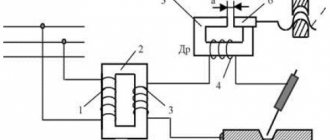
Filter choke with core gap
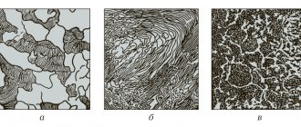
To reduce the drop in the magnetic permeability and inductance of the inductor with an increase in the bias current, a non-magnetic gap is introduced into the inductor core. Below are the magnetization curves of the core with and without gap.
Magnetization curves of the core material: without gap (1) and with gap (2).
As can be seen from the figure, the hysteresis loop of a core without a gap is line 1, and the hysteresis loop of a core with a non-magnetic gap is line 2. That is, curve 2 stretches and rotates relative to the zero coordinate. Thus, the inductor core, in the presence of a gap, the magnetization characteristic of which is linear, is saturated at relatively higher currents in the winding than the core without a gap.
From this we can conclude that when the bias current increases, it is necessary to select a larger non-magnetic gap to increase the inductance of the inductor.
The question arises of choosing the length of the non-magnetic gap in the core. In one of the articles I talked about how to calculate the equivalent magnetic permeability in the presence of a gap. Here the inverse problem is to calculate the length of the gap based on some given permeability, the expression will look like
where δ is the length of the non-magnetic gap, mm,
le – effective length of the magnetic field line, mm,
μe is the effective magnetic permeability of the core with a gap,
μr is the relative magnetic permeability of the core material. Since the value of the magnetic permeability of the core material is significantly greater than the required permeability μe << μr, the last term in the expression can be ignored.
Parallel oscillatory circuit.
If you connect an inductor and a capacitor, you get a very interesting element of radio engineering - an oscillatory circuit. If you charge a capacitor or induce E.M.F. in the coil using an electromagnetic field, the following processes will begin to occur in the circuit: The capacitor, when discharged, excites an electromagnetic field in the inductor. When the charge is depleted, the inductor returns the stored energy back to the capacitor, but with the opposite sign, due to the E.M.F. self-induction. This will be repeated again and again - electromagnetic oscillations of a sinusoidal shape will appear in the circuit. The frequency of these oscillations is called the resonant frequency of the circuit, and depends on the values of the capacitor capacitance (C) and the inductance of the coil (L).
A parallel oscillatory circuit has a very high resistance at its resonant frequency. This allows it to be used for frequency selection (selection) in the input circuits of radio equipment and intermediate frequency amplifiers, as well as in various master oscillator circuits.
How to test a throttle with a multimeter
We have figured out what a throttle is and what it is used for, now it’s also worth learning how to determine its performance. If the multimeter can measure inductance, everything is easy. We're just taking a measurement. If the throttle parameters are unknown to us, we set the largest measurement limit. Usually it's a few hundred Henrys. On the jackal they are designated by the Russian Gn or the Latin letter H.
Having set the multimeter switch to the desired position, we touch the coil terminals with the probes. A number appears on the screen. If the numbers are small, move the switch to one of the following positions, guided by the previous indicators.
Not all multimeters have an inductance measurement function.
For example, if 10 mH is displayed, we set the measurement limit to the nearest larger one. After this, we repeat the measurements. In this case, the inductance of the measured inductor will be displayed on the screen. Having passport data, you can compare real indicators with declared ones. They shouldn't be much different. If the difference is large, the throttle needs to be changed.
If the multimeter is simple, it does not have an inductance measurement function, but there is a resistance measurement mode, you can also check its performance. But in this case we will measure not inductance, but resistance. By measuring the winding resistance, we can simply understand whether the inductor is working or whether it is broken.
This way you can check the serviceability of the choke for fluorescent lamps
To test the throttle with a tester, move the multimeter switch to the resistance measurement position. We set the measurement limit, it is better to set the lower one in order to see the winding resistance. Next, use probes to touch the ends of the winding. Some resistance should appear. It should not be infinitely large (break) and should not be zero (short). In both cases, the throttle is not working, all other values are a sign of operability.
To make sure that there is no short circuit on the inductor turns, you can switch the multimeter to continuity mode and touch the leads with the probes. If it rings, there is a short, there is a breakdown somewhere, and this means that another choke is needed.
Checking in lamps
The throttle must be checked if one of the above-described phenomena is observed when the fluorescent lamp is operating, as well as if a characteristic smell of burning insulation is noticed, sounds that are not typical for the operation of the device are observed, and also if the lamp does not turn on.
Before checking the lamp choke, the lamp itself and the starter are checked.
A malfunction of the inductor may consist of a break or burnout of the coil wire or an interturn short circuit caused by breakdown or burning of the insulation.
Both malfunctions can occur either due to a long period of use of the device, or as a result of any mechanical impact. It is possible for the coil wire to burn out as a result of supplying it with a current greater than the maximum for which the inductor is designed.
If, when measured with a multimeter, the resistance is infinite, the coil wire has broken.
Type of chokes
There is a wide range of fluorescent lamps on the market. And each type of fluorescent lamp has its own choke transformer. For example, a DRL lamp and a HPS lamp cannot be lit by the same type of throttle. It's all about different parameters for starting and maintaining combustion. Here the voltage and current are different.
But the MGL lamp can operate both from the choke of the DRL lamp and from the HPS. But there is one point. The brightness of this light source will depend on the applied voltage. And the color temperature will be different.
Attention! Any choke transformer will “outlast” several lamps in terms of its service life. Of course, with the proviso that the lamp is used correctly
Types of chokes
But we have to take into account the fact that the lamp “gets old” over the years. A special alkali metal paste is applied to the tungsten electrodes of fluorescent fluorescent lamps. So this paste gradually evaporates, the electrodes are exposed, and, therefore, the voltage increases, which leads to overheating of the inductor. The end result can be two options:
- The coil winding will break, which will cut off the voltage supply to the electrodes.
- The coil will short-circuit. And this is connecting the lamp directly to the AC mains. The lamp will burn out - that’s for sure, or it may explode, which will lead to damage to the lamp as a whole.
Therefore, my advice is not to wait for the lamp to burn out on its own. There is a special replacement schedule that is determined by the manufacturer, and which must be strictly adhered to. When carrying out preventive maintenance, experienced electricians must check these lighting devices for the voltage parameter. If it approaches the normal limit, then the lamp is changed before its service life. It is better to replace an inexpensive lamp than an expensive choke transformer.
Let us add that manufacturers today offer improved protection systems for fluorescent lamps. Safety circuit breakers were added to their design, which are triggered when the voltage inside the gas-discharge light source increases.
Separation by purpose
In fact, all chokes are divided into two main groups, as are the lamps in which they are installed.
- Single-phase. They are used in household and office lamps connected to a 220 volt network.
- Three-phase. Connect to a 380 volt network. These include DRL and DNA lamps.
Based on their installation location, these devices are also divided into two groups:
- Built-in. They are also called open. Such chokes are installed in the lamp housing, which protects it from moisture, dust, and wind.
- Closed (sealed, waterproof). These devices have a special box that protects them. Such models can be installed outdoors in the open air.
Electronic throttle
Conclusions.
Although the scheme has a half-century history, it still remains relevant. Ballasts are necessary for the operation of a fluorescent lamp. All components are manufactured and inexpensive. The advantages of this scheme include its simplicity and accessibility of components. Typically, the inductor is the longest-lived component in the circuit.
Of the minuses, it was noted that when using the classic scheme, when the lighting is turned on, flickering is observed for several seconds. This has a bad effect on the useful life of the light source itself. Those. The lamp will work less in such a circuit than when using an electronic starter.
In terms of economic feasibility, if you frequently turn the light on and off, it is not profitable to use such an elemental base; it is easier to purchase an electronic starter, although its purchase will cost more, but it will be a one-time cost.
- Related Posts
- How to properly use emergency lighting with all current standards and requirements
- Light sources and what they are
- What is a base and lamps need one for it
Scope of application
When AC motors are turned on, there is a voltage surge. The choke in this case plays the role of a current limiter and protects the network from overload.
In voltage stabilizers, such a device serves to reduce the amplitude of alternating current and smooth out ripples.
In fluorescent lamps (FLL), the inductor performs two tasks:
- promotes ignition of the glow discharge after the starter is activated;
- prevents the lamp from flickering due to voltage surges in the network.
In inverters and switching power supplies, choke units are used to limit sudden surges of current. The device in question in this case plays the role of a filter.
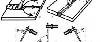
When choosing a welding machine, a dilemma arises: give preference to quality or price. The second, as a rule, wins. Cheaper “welders” are characterized by difficult arc ignition and metal spattering during welding due to current pulsations. The use of a choke in the welding machine circuit allows you to obtain a high-quality and even welding seam, simplifies ignition of the arc and its retention.
Damper adjustment
In order for the throttle valve to work like a clock, its sensor must be periodically adjusted. To do this, follow a few simple steps:
- The ignition is turned off to move the valve to the closed position.
- The sensor connector is de-energized.
- The sensor is adjusted using a 0.4 mm probe located between the screw and the lever.
To check the serviceability of the sensor, the voltage level is measured using an ohmmeter. If voltage is detected, the sensor should be replaced. In the opposite situation, you can continue to adjust the sensor.
As you know, the fuel system of a car is its vitality. If it is even slightly damaged, the car may unpleasantly surprise you at the most inopportune moment. If the throttle valve or another element of the assembly fails, the consequences can be disastrous. Therefore, it is much better not to skimp on car diagnostics if there is the slightest suspicion of a malfunction. Remember - safety on the road comes first.
Principle of operation
The principle of operation of an electric choke is to restrain a sharp increase in current and smooth out the voltage drop line. How an electric choke works can be seen in the example of a fluorescent lamp. To prevent the gas in the flask from burning, but gradually warming up, the coil gradually brings the current to the nominal value.
The incoming current “wastes” its strength to induce a magnetic field around the coil. When the magnetic flux reaches its maximum, the current will begin to flow unhindered through the coil.
Important! Chokes are found in all electrical circuits. Smoothing the initial electrical voltage protects the radio and electrical components from critical overloads
Inductance check
The presence in the arsenal of a multimeter of such a useful function as measuring the inductance of the coils will be useful for checking the compliance of the inductor with the characteristics stated in the reference literature. This feature is only available on some digital multimeter models.
To use this feature, you must set your multimeter to measure inductance. The probe contacts are connected to the coil terminals. For the first measurement, the multimeter is set to its largest measurement range, and then the range is reduced to obtain a measurement of sufficient accuracy.
When carrying out all measurements, it is important not to allow your hands to touch the contacts on which certain parameters are measured, otherwise the conductivity of the human body may change the readings of the device
How does a transformer work?
Let's consider the operation of a choke assembled on a closed magnetic circuit and connected as a load to an alternating current source. The number of turns and the magnetic permeability of the core are selected in such a way that its reactance is high, but the current flowing in the circuit is correspondingly not.
The current, periodically changing its direction, will excite an electromagnetic field in the winding of the coil (let's call it coil number 1), the direction of which will also periodically change - reversing the magnetization of the core. If an additional coil is placed on the same core (let’s call it number 2), then under the influence of the alternating electromagnetic field of the core, an induced variable E.M.F. will appear in it.
If the number of turns of both coils is the same, then the value of the induced E.M.F. very close to the value of the voltage of the power source applied to coil number 1. If the number of turns of coil number 2 is halved, then the value of the induced E.M.F. will decrease by half, if the number of turns is the opposite, increase - the induced E.M.F. will also increase. It turns out that for each turn there is a certain part of the voltage.
The winding of the coil to which the supply voltage is applied (number 1) is called primary, and the winding from which the transformed voltage is removed is called secondary.
The ratio of the number of turns of the secondary (Np) and primary (Ns) windings is equal to the ratio of their corresponding voltages - Up (primary winding voltage) and Us (secondary winding voltage).
Thus, a device consisting of a closed magnetic circuit and two windings in an alternating current circuit can be used to change the supply voltage - transformation. Accordingly, it is called a transformer.
If you connect any load to the secondary winding, a current (Is) will arise in it. This will cause a proportional increase in current (Ip) in the primary winding. The following ratio will be correct:
Transformers can be used both for converting the supply voltage and for decoupling and matching amplification stages
When working with transformers, you need to pay attention to a number of important parameters, such as: 1. Permissible currents and voltages for the primary and secondary windings
2. The maximum power of the transformer is the power that can be transmitted through it for a long time without causing overheating of the windings. 3. Operating frequency range of the transformer.
Application area
Inductors are used as:
- current limiters;
- saturation coils;
- anti-aliasing filters;
- magnetic amplifiers (MU);
- resonant circuits;
- electronic choke in radio, - and computer circuits.
Current limiters
Why chokes are needed as current limiters can be found in the following list:
- Coreless coils have low resistance, so they effectively limit the amount of short circuit current. Even the slightest reduction in short circuit arc power is of great importance.
- When starting powerful electric motors, the inductors are switched on. After the device reaches maximum speed, the coil is turned off by the starting device.
- In fluorescent lamps, electric chokes prevent the sudden switching on of maximum current. As a result, the mercury gradually warms up and passes into a vapor state. For DRL 250 lamps, the chokes are located inside the bulb. The chokes of the HPS lamps are located inside the casing separately from the bulb.
Note! The abbreviation DRL stands for Mercury Arc Lamp. HPS – Sodium Arc Tube
Saturation coils
After the magnetic field is saturated, the coil resistance stops increasing. Previously, saturation coils formed the basis of voltage stabilizers. Today they have been replaced by electronic systems.
Antialiasing filters
What is a throttle in electronics? These are smoothing filters that straighten the AC voltage ripple line. As a result, the stability of the electronic equipment is ensured. This filter looks like a barrel on a USB cable. Inside it is a single-turn coil. Electronic boards use chokes of the r68 brand.
Magnetic amplifiers (MU)
They were included in the electric motor control system. Magnetic induction in the core was saturated by magnetization of the core steel. The starter used several windings at once. Today, instead of magnetic starters, thyristor systems are used.
Magnetic starter circuit
Resonant circuits
A resonant circuit is used in tuners. An inductive coil in parallel with a capacitor is combined into a single system, which constitutes a resonant circuit. The circuit provides low resistance with a fixed frequency.