Operating principle
It is no secret that a pipeline system can place a large load on spans and supporting engineering structures. This impact is explained by the large weight of fittings, connecting fittings, pipes and other elements that are an integral part of heat supply systems, as well as main and technological transportation lines.
In most cases , pipes are made of metal, which is necessary to ensure maximum structural reliability . However, the use of such material significantly increases its size. And if the pipe contains technological products that use a liquid coolant (if we are talking about heating mains), the weight of a linear meter of pipe increases rapidly. The load becomes maximum when pumping liquid substances, including drinking water and hot water supply, water with antifreeze of heating mains, process solutions, suspensions.
In addition to statistical loads, the operation of the system is accompanied by thermal changes in the linear dimensions and diameters of the component . This is due to seasonal temperature fluctuations and climatic factors. Also, the transported product itself, which fills all the internal spaces, has a special influence on the pipeline. To understand, hot steam can lengthen one linear meter of the steam pipeline by 1.2 millimeters, resulting in a longitudinal displacement of some sections of the system.
The pipes are also affected by torques, transverse and axial loads when pumping a liquid substance. Transportation is complicated by gusts of wind, water hammer, vibrations and other unpleasant incidents.
Specifications
| Designation | Diameter Dн, mm | Vertical load, kgf | Height H, mm | Height H1, mm | Width B, mm | Cushion width l, mm | Length L, mm | Weight, kg |
| T14.01 | 32; 38; 45 | 120 | 100 | 104 | 50 | — | 340 | 1,28 |
| T14.02 | 32; 38; 45 | 120 | 150 | 154 | 50 | — | 340 | 1,74 |
| T14.03 | 32; 38; 45 | 120 | 200 | 204 | 50 | — | 340 | 2,20 |
| T14.04 | 57; 76 | 220 | 100 | 108 | 70 | — | 340 | 1,55 |
| T14.05 | 57; 76 | 220 | 150 | 168 | 70 | — | 340 | 2,06 |
| T14.06 | 57; 76 | 220 | 200 | 208 | 70 | — | 340 | 2,64 |
| T14.07 | 89; 108 | 400 | 100 | 113 | 90 | — | 340 | 1,84 |
| T14.08 | 89; 108 | 400 | 150 | 163 | 90 | — | 340 | 2,39 |
| T14.09 | 89; 108 | 400 | 200 | 213 | 90 | — | 340 | 2,98 |
| T14.10 | 133;159 | 800 | 100 | 118 | 120 | — | 340 | 2,25 |
| T14.11 | 133;159 | 800 | 150 | 168 | 120 | — | 340 | 2,89 |
| T14.12 | 133;159 | 800 | 200 | 218 | 120 | — | 340 | 3,54 |
| T14.13 | 194 | 2200 | 100 | 148 | 180 | 50 | 340 | 6,17 |
| T14.14 | 194 | 2200 | 150 | 198 | 180 | 50 | 340 | 7,80 |
| T14.15 | 194 | 2200 | 200 | 248 | 180 | 50 | 340 | 9,36 |
| T14.16 | 219 | 2200 | 100 | 136 | 180 | 50 | 340 | 6,87 |
| T14.17 | 219 | 2200 | 150 | 186 | 180 | 50 | 340 | 7,46 |
| T14.18 | 219 | 2200 | 200 | 236 | 180 | 50 | 340 | 9,07 |
| T14.19 | 273 | 2200 | 100 | 125 | 180 | 50 | 340 | 5,33 |
| T14.20 | 273 | 2200 | 150 | 175 | 180 | 50 | 340 | 7,20 |
| T14.21 | 273 | 2200 | 200 | 225 | 180 | 50 | 340 | 8,81 |
| T14.22 | 325 | 7000 | 100 | 165 | 280 | 50 | 340 | 10,58 |
| T14.23 | 325 | 7000 | 150 | 215 | 280 | 50 | 340 | 13,28 |
| T14.24 | 325 | 7000 | 200 | 265 | 280 | 50 | 340 | 15,29 |
| T14.25 | 377 | 7000 | 100 | 152 | 280 | 50 | 340 | 10,04 |
| T14.26 | 377 | 7000 | 150 | 202 | 280 | 50 | 340 | 12,23 |
| T14.27 | 377 | 7000 | 200 | 252 | 280 | 50 | 340 | 15,47 |
| T14.28 | 426 | 7000 | 100 | 142 | 280 | 50 | 340 | 9,29 |
| T14.29 | 426 | 7000 | 150 | 192 | 280 | 50 | 340 | 12,04 |
| T14.30 | 426 | 7000 | 200 | 242 | 280 | 50 | 340 | 14,68 |
| T14.31 | 480 | 12500 | 100 | 174 | 380 | 50 | 340 | 20,55 |
| T14.32 | 480 | 12500 | 150 | 224 | 380 | 50 | 340 | 25,45 |
| T14.33 | 480 | 12500 | 200 | 274 | 380 | 50 | 340 | 30,76 |
| T14.34 | 530 | 12500 | 100 | 164 | 380 | 50 | 340 | 19,81 |
| T14.35 | 530 | 12500 | 150 | 214 | 380 | 50 | 340 | 24,76 |
| T14.36 | 530 | 12500 | 200 | 264 | 380 | 50 | 340 | 29,78 |
| T14.37 | 630 | 12500 | 100 | 150 | 380 | 50 | 340 | 19,02 |
| T14.38 | 630 | 12500 | 150 | 200 | 380 | 50 | 340 | 23,96 |
| T14.39 | 630 | 12500 | 200 | 250 | 380 | 50 | 340 | 29,06 |
| T14.40 | 720 | 22000 | 100 | 185 | 500 | 80 | 340 | 27,42 |
| T14.41 | 720 | 22000 | 150 | 235 | 500 | 80 | 340 | 33,41 |
| T14.42 | 720 | 22000 | 200 | 285 | 500 | 80 | 340 | 39,48 |
| T14.43 | 820 | 22000 | 100 | 172 | 500 | 80 | 340 | 26,56 |
| T14.44 | 820 | 22000 | 150 | 222 | 500 | 80 | 340 | 32,56 |
| T14.45 | 820 | 22000 | 200 | 272 | 500 | 80 | 340 | 38,60 |
| T14.46 | 920 | 36000 | 100 | 158 | 500 | 80 | 340 | 33,85 |
| T14.47 | 920 | 36000 | 150 | 208 | 500 | 80 | 340 | 41,76 |
| T14.48 | 920 | 36000 | 200 | 258 | 500 | 80 | 340 | 50,02 |
| T14.49 | 1020 | 36000 | 100 | 218 | 700 | 80 | 340 | 50,45 |
| Т14.50 | 1020 | 36000 | 150 | 268 | 700 | 80 | 340 | 60,87 |
| T14.51 | 1020 | 36000 | 200 | 318 | 700 | 80 | 340 | 71,59 |
| T14.52 | 1220 | 36000 | 100 | 195 | 700 | 80 | 340 | 52,29 |
| T14.53 | 1220 | 48000 | 150 | 245 | 700 | 80 | 340 | 62,71 |
| T14.54 | 1220 | 48000 | 200 | 295 | 700 | 80 | 340 | 73,15 |
| T14.55 | 1420 | 36000 | 100 | 172 | 700 | 120 | 340 | 62,36 |
| T14.56 | 1420 | 60000 | 150 | 222 | 700 | 120 | 340 | 73,15 |
| T14.57 | 1420 | 60000 | 200 | 272 | 700 | 120 | 340 | 88,58 |
What are pipeline supports needed for?
To ensure maximum reliability and safety for the pipeline system, not only high-quality components are used, but also reliable support in the designed position. Such a product perceives and correctly distributes the acting loads on the ground or any other base.
An important advantage of the supports is the protection of pipes from bending and disconnection of connecting elements at joints . The structures are equipped with elastic gaskets that are sandwiched between the pipeline and the support.
Sliding devices are characterized by one unique feature: their base is not fixed to the concrete surface, but moves freely along a horizontal plane . To support the pipes, embankments, trenches, racks and shelves are used, on which there are special support shoes. Sometimes the pipeline is also attached to the walls using brackets.
When laying heating mains, a support pad is mounted under the base of the pipes in the tray before routing the heating plants. The solution protects the structure from abrasion and deformation when temperature changes and other climatic factors occur.
Pipe hangers and supports
PC Empire LLC offers supports of all types to order. It is possible to manufacture supports according to customer drawings. Tel: (343) 213-88-89, email
When installing and securing all types of pipelines, supports are usually used. Supports are divided into fixed and movable. Based on the method of fastening the pipe, supports are divided into welded and clamped. It is not uncommon to use staples instead of clamps for pipe installation. Fixed supports rigidly hold the pipe and do not allow it to move due to any vibrations or shifts. Fixed supports perceive vertical loads from the weight of the pipeline and the environment, horizontal (axial) loads from thermal changes and expansion of the pipeline and frictional forces of movable supports, as well as loads from hydraulic shock, vibration and pulsation. The housings of the fixed supports are welded and bolted to the supporting structures of the pipeline. In clamp fixed supports, to reduce the slippage of the pipe in the support, special stops are welded to the pipe. Depending on the magnitude of the axial forces perceived by the support, the stops can be made with one or two clamps or brackets. The main types of fixed supports are shown in drawing 1.
Drawing 1. Main types of fixed pipeline supports: a - welded support, b - clamp support, c - clamp support for pipelines with refrigerant, d - frameless support
Movable supports are designed to support the pipeline and allow it to move freely under the influence of temperature expansion and deformation. They take only the vertical load from the weight of the pipeline, the weight of the product, as well as the insulation. Movable supports have several varieties, such as: sliding, roller, guides, spring, ball bearings, etc. The most popular are sliding supports, which slide and move along with the pipe along the surface of the supporting structures of the pipeline. To reduce the friction force between the fifth support and the supporting surface, it is recommended to use roller bearings; which in turn are included in one of the varieties of sliding supports, but installed on rollers. Guide supports are those supports that have guide strips or frameless clamp supports in which the pipe slides directly along the surface of the supporting structure and is held from lateral displacement by the clamp. On pipelines subject to vibration loads, spring supports are used to minimize or completely absorb vibration. Ball bearings are installed in places where a large-diameter pipeline turns, where it is required to allow its free movement along both horizontal axes. Some of the popular movable supports are shown in the drawing. 2.
Drawing. 2. Designs of movable supports for pipelines: a - welded sliding, b - clamp sliding, c - clamp sliding double-roller, d - clamp sliding for pipelines with refrigerant, e - guide
The supports are usually made of steel St. 3 cold stamping. On request it is possible to manufacture from other grades of steel. Also, for fastening horizontal pipelines, in addition to supports, hangers (suspended fastenings) can be used. Suspended fastenings are suspended from the building ceiling, brackets, consoles using rods with bolts or welded eyes. The dimensions of the rods are specified locally. Basically, suspensions use rods with right- and left-hand threaded couplings, adjustable in length.
Horizontal pipelines, which are equipped with vertical sections, and the extension of which is perceived by the horizontal branch, are mounted on spring hangers. Installation of rigid hangers for fastening vertical pipelines on such sections of the pipeline is not allowed, since with temperature expansion the permissible load on the hangers may be uneven. Spring hangers are widely used in pipelines prone to frequent vibrations. The main designs of suspensions are shown in the drawing. 3.
Drawing. 3. Suspension designs: a - rigid for horizontal pipelines, b - spring for horizontal pipelines, c - spring for vertical pipelines; 1 — clamp, 2 — earring, 3 — eye, 4 — rod, 5 — spring block, 6 — disks, 7 — spring, 8 — stop
Supporting load-bearing structures for pipelines, depending on the place of their application, the magnitude of the operating loads and other factors, are used in the form of masts and racks, trestles, brackets, and consoles.
Design and its varieties
The pipeline support includes several separate parts. Among them:
- base made of channel or corner;
- fastening of holders;
- paronite gaskets;
- semicircular holders;
- special skating rinks;
- connecting nuts, bolts and washers.
These days, the following types of supports are widespread:
Representatives of the first group ensure efficient sliding of pipes along the guide elements due to the roller. Such structures will be indispensable when connecting pipes in tunnels, where there is a need to support the pipeline along the axis. Movement is limited using special stops. Single-roller and double-roller sliding bearings are available in the market.
As for clamp models, they are capable of providing high system stability to unexpected loads. The hangers used in the design are necessary for efficient movement of pipes.
Read also: How a gas burner works
As SNiP standards state, the supports of a pipeline system can be movable or fixed. As for mobile species, they are represented by:
- sliding clamps - necessary for moving pipes in a specific direction;
- dielectric - characterized by the presence of dielectric gaskets made of paronite, providing the system with reliable protection from the possible effects of static electricity;
- roller - move along their own axis when thermal deformation occurs;
- ball - capable of performing axial and transverse displacement of pipes;
- clamps with a bracket - designed to move pipes in a specific direction.
When choosing the appropriate option for your purposes, pay attention not only to the design characteristics of a particular model, but also to the calculation results obtained by certain general measurements.
Directory of rolled metal products
Sliding supports are an important part of any pipeline system. This is a type of rolled metal that bears most of the power load of the pipeline, which as a result is transferred to the soil and structures. The process of selecting supports and reinforcement is a responsible task that requires increased attention to certain factors of their operation. For example, it should be remembered that the design forces and operating conditions of the product are the determining factor in determining the appropriate type of support. By increasing the diameter of the pipe, the friction force in the supports also becomes greater. Sometimes, the location of the pipes is so specific that it is simply impossible to use different types of supports. Then pendants are used in the work.
Features of the device and purpose divide the supports into fixed and movable (sliding).
Each of the presented types, like woven steel mesh, has a number of specific characteristics that determine the quality level and cost of the finished product, as well as the specifics of its use. Sliding supports are an element of the pipeline system that supports its operation, promotes uniform distribution of deformations under the influence of temperatures, without being an obstacle to the unhindered movement of pipes.
The main and main function of sliding supports is to promote resistance to vertical loads during the period of active use of the pipeline. Allows for unhindered thermal movement of products in the axial and cross sections along load-bearing structures. The properties and characteristics of products depend on the material used for their production. Thus, the NZ square, high-quality NZ circle and NZ angle are rolled metal products characterized by high quality and performance characteristics.
The friction force, which is measured between the heel and the supporting surface, is reduced by the roller bearings used. Spring supports exhibit excellent resistance to vibration loads. The properties of ball-type supports at the turning points of pipes of significant diameter allow the pipes to move freely along both horizontal axes. The widely known suspended type of supports is designed for direct fastening of horizontal pipelines. Welded springs and rods with bolts, the size of which corresponds to specific operating conditions, are used as their fastening. The correct choice requires knowledge of certain product parameters. Among the main values: the height of the supports, the size of the outer diameter of the pipe being pulled, the number of supports, the possibility of using reinforcement.
| Designation | Outer diameter, dн | Height, mm | Length, mm | Width, mm | Weight, kg |
| Dielectric support T18.01 | 194 | 100 | 680 | 180 | 14,59 |
| Dielectric support T 18.02 | 150 | 17,23 | |||
| Dielectric support T18.03 | 200 | 19,77 | |||
| Dielectric support T18.04 | 219 | 100 | 14,71 | ||
| Dielectric support T18.05 | 150 | 17,31 | |||
| Dielectric support T18.06 | 200 | 19,93 | |||
| Dielectric support T18.07 | 273 | 100 | 16,95 | ||
| Dielectric support T18.08 | 150 | 19,83 | |||
| Dielectric support T18.09 | 200 | 22,43 | |||
| Dielectric support T18.10 | 325 | 100 | 280 | 26 | |
| Dielectric support T18.11 | 150 | 30,19 | |||
| Dielectric support T18.12 | 200 | 33,75 | |||
| Dielectric support T18.13 | 377 | 100 | 29,2 | ||
| Dielectric support T18.14 | 150 | 33,47 | |||
| Dielectric support T 18.15 | 200 | 37,69 | |||
| Dielectric support T 18.16 | 100 | 30,77 | |||
| Dielectric support T18.17 | 150 | 35,04 | |||
| Dielectric support T18.18 | 200 | 39,26 | |||
| Dielectric support T18.19 | 426 | 100 | 33,67 | ||
| Dielectric support T18.20 | 150 | 37,96 | |||
| Dielectric support T18.21 | 200 | 42,1 | |||
| Dielectric support T 18.22 | 480 | 100 | 380 | 58,59 | |
| Dielectric support T18.23 | 150 | 66,07 | |||
| Dielectric support T18.24 | 200 | 73,65 | |||
| Dielectric support T18.25 | 530 | 100 | 61,42 | ||
| Dielectric support T18.26 | 150 | 68,88 | |||
| Dielectric support T18.27 | 200 | 76,46 | |||
| Dielectric support T18.28 | 630 | 100 | 62,88 | ||
| Dielectric support T18.29 | 150 | 70,36 | |||
| Dielectric support T18.30 | 200 | 77,92 | |||
| Dielectric support T18.31 | 720 | 100 | 500 | 79,48 | |
| Dielectric support T18.32 | 150 | 88,24 | |||
| Dielectric support T18.33 | 200 | 97,12 | |||
| Dielectric support T18.34 | 820 | 100 | 83,34 | ||
| Dielectric support T18.35 | 150 | 92,08 | |||
| Dielectric support T18.36 | 200 | 100,96 | |||
| Dielectric support T18.37 | 920 | 100 | 123,14 | ||
| Dielectric support T18.38 | 150 | 134,76 | |||
| Dielectric support T18.39 | 200 | 146,84 | |||
| Dielectric support T18.40 | 1020 | 100 | 700 | 130,42 | |
| Dielectric support T18.41 | 150 | 165,28 | |||
| Dielectric support T18.42 | 200 | 180,34 | |||
| Dielectric support T18.43 | 1220 | 100 | 169,05 | ||
| Dielectric support T18.44 | 150 | 183,71 | |||
| Dielectric support T18.45 | 200 | 198,59 | |||
| Dielectric support T18.46 | 1420 | 100 | 193,67 | ||
| Dielectric support T18.47 | 150 | 211,91 | |||
| Dielectric support T18.48 | 200 | 230,81 |
Pipeline system supports comply with current legislation and standards. Regulatory documentation used to control the quality of products, including electrodes, contains all the necessary dimensions, permissible loads and regulates the quality and properties of the material used for the production of rolled products.
Features of sliding type supports
In most cases, thermal shrinkage does not affect the operation of the piping system. Sliding elements provide a quick solution to many shrinkage problems. They can support the pipe, leaving only vertical loads. Thus, partial fixation protects the system from unexpected stress when temperature changes. True, for fixed structures, even a small voltage can be fatal and lead to damage.
Despite the contradiction presented above, sliding structures are fixed directly to the pipe, where they slide along its base. In this case, the intensity of abrasion of the pipe during transportation is reduced. There are a number of factors that can lead to permanent or minor shifts. We are talking about:
- changes in pressure inside the system;
- systematic temperature shrinkage;
- vibrations.
If the support is not attached securely enough, dust and dirt, which have characteristic abrasive properties, will begin to appear in the gap formed. Over time, they begin to thin the pipe wall, creating a stress riser. Ultimately, she simply can’t stand it.
Currently, sliding supports for pipelines are sold as a complete set, which includes all related elements. Therefore, you can independently choose the appropriate solution for a specific installation height and pipe diameter. It is better to entrust the installation of the structure to a qualified specialist, since it is problematic to take into account many subtleties on your own without skills and experience. A professional employee will take into account all non-obvious aspects and minimize the likelihood of accidents, reducing the cost of system maintenance.
Movable support
Sliding supports for pipelines in polyurethane foam insulation.
Price
Pipelines of heating networks are dynamic systems, the significant mass of which, as well as changes in pressure and operating temperature loads, lead to constant axial and transverse movements and for their stable maintenance in working planes, self-compensation, protection from vibration and movement within the design parameters, special devices are used , including the so-called sliding supports (movable supports, movable support) or an articulated movable support.
The main purpose of a sliding support for pipes (sliding support PPU), used for PPU insulated pipes of heating networks of overhead or channel installation methods, is to vertically support a certain straight section of the pipeline and protect the insulating and thermal insulation coating of the PPU pipe from damage during operation. The difference between this type of movable sliding support is that the sliding support (supports for polyurethane foam pipes), unlike the principle of operation, the support is stationary and works without fixing the polyurethane foam pipe.
Sliding supports (moving supports for heating networks) are designed for PPU heating network pipelines, both underground and above-ground installation and cover the entire range of diameters of pre-insulated pipelines within nominal diameters from 32 to 1220 mm. According to the route of the heating network pipeline, taking into account the slope of the heating main and the distribution of the load over measured sections, concrete bases with steel insert plates are installed, to which the finished sliding support products (movable support) are welded.
Movable pipeline supports, sliding supports, supplied by the RosMTS group of companies, consist of a base made of a channel and two pairs of narrow semicircular supports (clamps) made of a steel strip, the lower of which are attached to it, and the upper holders are attached to the lower ones with bolts and nuts.
Production of sliding supports. Sliding support
During the installation of the sliding supports, a polyurethane foam insulation pipe with a steel outer shell is laid on the lower pair of half-rings lying at the base of the movable support for pipes. Then the second pair of half-rings from the strip is placed on the polyurethane foam pipe and attached to the bottom pair. That's all for installing the sliding supports. To protect the outer steel shell of the polyurethane foam pipe from damage from friction, an insulating wear-resistant material (usually rubber) is laid between it and the support. To protect against corrosion, the sliding supports (movable clamp support) are coated with an anti-corrosion coating. The dimensions and design of the sliding support, sliding clamp support for polyurethane foam pipes of insulated pipelines of heating networks are determined in the table of GOST 30732-2006.
Manufacturing of sliding supports Sliding support, movable sliding support
Diameter, d, mm
| DxS, mm | IN | L | ||
| Wrapped in polyethylene | Sheathed in galvanized steel | |||
| 32 | 125×3,0 | 125×1 | 100 | 320 |
| 38 | 125×3,0 | 125×1 | ||
| 45 | 125×3,0 | 125×1 | ||
| 57 | 125×3,0 | 125×1 | ||
| 140×3,0 | — | |||
| 76 | 140×3,0 | 140×1 | ||
| 160×3,0 | — | |||
| 89 | 160×3,0 | 160×1 | ||
| 180×3,0 | — | |||
| 108 | 180×3,0 | 180×1 | ||
| 200×3,2 | — | 140 | 470 | |
| 133 | 225×3,5 | 225×1 | ||
| 250×3,9 | — | |||
| 159 | 250×3,9 | 250×1 | ||
| 219 | 315×5,6 | 315×1 | 280 | 670 |
| 273 | 400×6,3 | 400×1 | ||
| 450×7,0 | — | |||
| 325 | 450×7,0 | 450×1 | ||
| 426 | 560×8,8 | 560×1 | ||
| 530 | 710×11,1 | 675×1 | ||
| 630 | 800×12,5 | 775×1 | 600 | 770 |
| 720 | 900×14,0 | 875×1 | ||
| 820 | 1000×15,6 | 975×1 | 970 | |
| 1100×17,6 | — | 800 | ||
| 920 | 1100×17,6 | 1075×1 | ||
| 1200×19,6 | — | |||
| 1020 | 1200×19,6 | 1175×1 | ||
| 1220 | — | 1375×1 | 1200 | |
Take this opportunity to find out from our managers the cost of sliding supports, moving support price, sliding supports price, request sliding support price.
Movable supports GOST?
Movable supports are manufactured in accordance with GOST 30732-2006.
Sliding weight support?
The weight of the sliding support is directly dependent on the diameter.
GOST sliding bearings?
Sliding supports are manufactured in accordance with GOST 30732-2006.
Distance between sliding supports?
The distance between the sliding support;
Sliding supports must be installed at a strictly defined distance, which depends on several criteria and is calculated separately for each type of pipeline. The distance between sliding supports is influenced by several criteria:
- Outer diameter of pipes. The larger the diameter, the greater the distance between the sliding supports.
- Pipeline type. Sliding supports under cold water pipes are installed at a greater distance than at high temperatures.
- Pipe location. For a vertical pipeline, the distance between the sliding supports should be 10% greater than in sections with horizontal pipes.
Package of services; from the project to the act of acceptance of the facility into operation.Installation of heating mains,
- installation of heating pipes,
- ppu installation,
- installation of PPU pipes,
- installation of PPU shells,
- training enterprise employees on the rules for installing pipelines from pipes in polyurethane foam insulation.
- For questions regarding cooperation, please contact the technical director
- Lemtyugov Andrey Anatolyevich mob. tel. +7 915 999 9581
see also:
- heat-shrinkable couplings.
- components for filling joints.
- polyurethane foam shell.
- heat-shrinkable tapes.
- Insulation of pipe joints PPU PE Options
- Technologies for insulating joints with heat-shrinkable sleeves
- Couplings with embedded elements Joint insulation technology
- Bellows expansion joints PPU, KSU PPU
- Fixed supports
- Sliding supports
- Description of steel pipelines in polyurethane foam insulation
- Technical characteristics of polyurethane foam pipe
The exact distance between the sliding supports with specific parameters can be clarified with our specialists.
- Address: Russia, Yaroslavl, st. Shchapova, 20
- Phones
- Tel/fax
E-Mail: Order on-line mobile. 8 915 999 9382, 8 915 999 9588 Home To catalog of pipeline products with polyurethane insulation
Advantages
The popularity of sliding supports is due to many advantages and design features. Among them:
- no installation difficulties;
- long service life, regardless of operating conditions;
- reliable and durable design that can withstand maximum loads;
- the presence of various standard sizes, which expands the possibilities for finding a suitable solution for a specific case.
The support is one of the most indispensable components of any heating system. Its absence significantly reduces the life of the pipeline and increases the risk of all kinds of damage under the influence of certain factors.
When choosing the appropriate solution for an individual case, do not forget that a good design maintains the basic position of the pipe on the support sheet as accurately as possible, preventing the aggressive influence of wind or seismic shocks. It also guarantees support for pipes of any weight and diameter with minimal wall stress. As a result, there is no chance of dents or damage. Sliding type supports have high load-bearing capacity at relatively low resource costs.
The market offers a large range of standardized designs, which expand the possibilities of choice and allow you to find any modification that is ideal for your conditions.
When choosing the type of support structure, experts pay attention to both the calculated indicators of the expected forces and the process of interaction between the components. In most cases, designers give preference to support shoes with an anti-friction coating (fluoroplastic), which rest on a support pad (a concrete slab can be used as it). This solution has a positive effect on the sliding of the conventional steel-concrete combination, providing a friction coefficient of 0.5. It makes sense to use roller or ball type supports with a friction coefficient of 0.1.
Read also: How to connect a two-key switch to two light bulbs
A high-quality sliding structure can protect main pipelines from unexpected damage and loads, compensating for thermal expansion, vertical and lateral loads, as well as smoothing torque and leveling other physical impacts. As a result, the client is provided with colossal financial savings on repair work, and the likelihood of any unpleasant “surprises” is reduced.
Given these characteristics, sliding supports are an indispensable part of any modern pipeline. The cost of products varies and ranges from several hundred rubles to tens of thousands. It all depends on weight, length, dimensions, design and operational properties, as well as some other aspects.
As for the areas of application, they are indeed very extensive and are constantly expanding. Most often, sliding support is used in:
- metallurgy;
- mechanical engineering;
- oil refining industry;
- construction;
- thermal power engineering;
- housing and communal services;
- gas production
Movable supports GOST 14911-82
The standard does not apply to supports of main pipelines, pipelines with refrigerant, intra-station pipelines of power plants, pipelines of heating networks, as well as pipelines laid on permafrost and heaving soils and in seismic areas. 2. The main dimensions of the movable supports of steel pipelines must correspond to those indicated in drawing 1-4 and table 1-4. Round holes in the body (1) of supports of types P2, PZ, X2, XZ and in the rib (2) of supports of types P1, X1 should be made at the request of the consumer. 3. At the request of the consumer, it is allowed not to make holes in the body (1) of supports of types PZ and KhZ, located from the vertical axis of the support at a distance of 1/4 l. (Changed edition, Amendment No. 1).
Classification, technical requirements, acceptance rules, test methods, marking, packaging, transportation, storage of supports under the manufacturer's warranty - in accordance with GOST 22130-76.
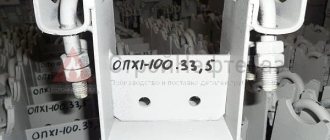
Supports OPP 1 and OPH 1
Support OPP 1
Support OPH1
1—body: 2—rib; 3—eye: 4—clamp; 5—nut according to GOST 5915-70. Drawing 1 Dimensions of supports OPP 1 and OPP 1 mm
| dh | r | h | h1 | h2 | a | b | d |
| 18; 21,3 | 11 | 70 and 100 | 30/60 | 77/107 | 34 | 40 | M8 |
| 25; 26,8 | 14 | 38 | |||||
| 32; 33,5 | 17 | 84/114 | 44 | 60 | M10 | ||
| 38; 42,3 | 22 | 54 | |||||
| 45; 48 | 25 | 62 |
Table 1
Notes: 1. Dimensions h1 and h2 are given for two values of h: in the numerator for h=70 mm and in the denominator for h=100 mm.
2. Overall height h2 is not indicated on the drawing and is not subject to control. Supports OPP 2 and OPP Z
1—body; 2—rib. Drawing 2 Dimensions of supports OPP 2 and OPP Z with height h=100 and 150 mm
| dh | b | l | s | A |
| 57; 60; 75,5; 76 | 55 | 170, | 3 | 34 |
| 88,5; 89 | ||||
| 108, 114, 127, 133, 140 | 100 | 45 | ||
| 159, 165 | 4 | |||
| 194, 219, 273 | 190 | |||
| 325, 377, 426 | 280 | 220 | 6 | 60 |
| 530, 480 | 400 | 70 | ||
| 630, 720, 820, 920 | 8 | |||
| 1020 | 10 | |||
| 1220, 1420, 1620 | 520 |
Table 2 Supports OPKH 2 and OPKH Z with height h-100 and 150 mm
Support OPH 2
Support OPH 3
1—body; 2—rib; 3—eye; 4—clamp; 5—nut according to GOST 5915-70; 6—stop for dh = 377 mm or more; 7—pillow. Drawing 3
Note: The angle of 150° of the cushion (7) should be taken for pipeline supports with an outer diameter (dh) of 308 and 194 mm and 120° for pipeline supports with other outer diameters.
Dimensions of supports OPKH 2 and OPKH Z with height h= 100 and 150 mm mm
| dh | h1 | A | a1 | b | b1 | l | l1 | l2 | s | d |
| 57; 60 | 35 | 86 | — | 55 | 34 | 170 | 50 | 30 | 3 | M10 |
| 75,5: 76 | 90 | M12 | ||||||||
| 88,5; 89 | 106 | |||||||||
| 108; 114 | 45 | 136 | 120 | 100 | 45 | 38 | ||||
| 133 | 150 | M16 | ||||||||
| 159 | 180 | 4 | ||||||||
| 194 | 50 | 230 | 100 | 190 | 70 | 56 | ||||
| 219 | 242 | M20 | ||||||||
| 273 | 70 | 298 | M24 | |||||||
| 325 | 90 | 350 | 150 | 280 | 60 | 220 | 6 | |||
| 377 | 402 | |||||||||
| 426 | 110 | 456 | ||||||||
| 480 | 508 | 380 | 70 | |||||||
| 530 | 120 | 558 | 400 | |||||||
| 630 | 145 | 658 | 140 | 440 | 80 | 8 |
Table 3 Supports OPB 1 and ODB 2
Support OPB 1
Support ODB 2
1—clamp; 2—pillow; 3—nut according to GOST 5915-70. Drawing 4 Dimensions of supports OPB1 and OPB2
| dh | r | a | b | l | h1, no more | d |
| 18; 21,3 | 11 | 34 | 20 | 50 | 8 | M8 |
| 23; 26,8 | 14 | 38 | ||||
| 32; 33,5 | 17 | 44 | M10 | |||
| 38; 42,3 | 21 | 54 | ||||
| 44.5; 45,48 | 24 | 62 | ||||
| 57; 60 | 29 | 70 | 50 | |||
| 75,5; 76 | 38 | 90 | M12 | |||
| 88,5; 89 | 45 | 106 | 100 | |||
| 108 | 54 | 122 | 12 | |||
| 114 | 57 | 136 | ||||
| 133 | 67 | 150 | 100 | 150 | M16 | |
| 159 | 80 | 180 | ||||
| 194 | 97 | 230 | 200 | |||
| 219 | BY | 242 | 16 | M20 | ||
| 273 | 137 | 298 | 200 | |||
| 325 | 163 | 350 | ||||
| 377 | 189 | 402 | ||||
| 426 | 213 | 456 | 300 | 200 | 16 | M24 |
| 480 | 240 | 508 | 350 | |||
| 530 | 265 | 558 |
Table 4
4. The brand of the support must consist of a symbol name (OP), type of support, height of the support (h), outer diameter of the pipeline (dh), indication of the presence of all round holes in the body and ribs (o) or part of the round holes in the body (p), indications of the presence of a satellite (c) and designations of this standard. An example of a symbol for a brand of support type PZ, height h=100 mm, for a steel pipeline with an outer diameter dh=194 mm, with all round holes in the body, with a satellite: OPPZ - 100.194 os GOST 14911-82 The same, with part of the round holes in the housing: OPPZ-100.194 ochs GOST 14911-82 The same, without holes in the housing, without a satellite: OPPZ-100.194 GOST 14911-82 The same, type B1, for a steel pipeline with an outer diameter dh = 194 mm: OPB1-194 GOST 14911-82 (Changed edition, Amendment No. 1).
5. Brands of supports, weight and calculated maximum vertical loads on supports are indicated in the reference appendix
APPENDIX
Reference Weight of supports and calculated maximum vertical loads on supports
| Brand of support | Weight, kg. no more | Estimated maximum vertical load, N (kgf), at working environment temperatures, °C | ||
| up to 150 | St. 150 to 300 | St. 300 to 450 | ||
| I | 2 | 3 | 4 | 5 |
| OPP 1-70.18 OPP 1-70.21.3 | 0,43 | 21570(2200) | 18630(1900) | 10790(1100) |
| OPP 1-70.25 OPP 1-70.26.8 | ||||
| OPH 1-70.18 | 0,78 | |||
| OPH 1-70.25 | 0,80 | |||
| OPP 1-70.32 OPP 1-70.33.5 | 0,51 | |||
| OPP 1-70.38 OPP 1-70.42.3 | ||||
| OPP 1-70.45 OPP 1-70.48 | ||||
| OPH 1-70.32 | 0,90 | |||
| OPH 1-70.38 | 0,97 | |||
| OPH 1-70.45 | 1,00 | |||
| OPP 1-100.18 OPP 1-100.21.3 | 0,60 | 14710(1500) | 13230(1350) | 7550 (770) |
| OPP 1-100.25 OPP 1-100.26.8 | ||||
| OPH 1-100.18 | 0.90 | |||
| OPC 1- 100.25 | 0,94 | |||
| OPP 1-100.32 OPP 1-100.33.5 | 0,62 | |||
| OPP 1-100.38 OPP 1-100.42.3 | ||||
| OPP 1-100.45 OPP 1-100.48 | ||||
| OPH 1-100.32 | 1,05 | 14710P500) | 13230(1350) | 7550(770) |
| OPH 1-100.38 | 1.10 | |||
| OPH 1-100.45 | 1.11 | |||
| OPP 2-100.57 OPP 2-100.60 | 1.24 | 44130(4500) | 33340(3400) | 18140(1850) |
| OPC 2-100.57 OPC 2-100.60 | 1,70 | |||
| OPP 2-10.0.75.5 OPP 2-100.76 | 1,17 | 49030(5000) | 37260(3800) | 20100(2050) |
| OPC 2-100.75.5 OPC 2-100.76 | 1,90 | |||
| OPP 2-100.88,5 OPP 2-100.89 | 1,15 | 53940(5500) | 40700(4150) | 22060(2250) |
| OPC 2-100.88.5 OPC 2-100.89 | 2,90 | |||
| OPP 2-100.108 OPP 2-100.114 OPP 2-100.127 | 1,63 | 56390(5750) | 42660(4350) | 23040(2350) |
| OPC 2-100.108 OPC 2-100.114 OPC 2-100.127 | 3,40 | |||
| OPP 2-100.133 OPP 2-100.140 | 1,62 | 59820(6100) | 45600(4650) | 24520(2500) |
| OPC 2-100.133 OPC 2-100.140 | 4,40 | |||
| OPP 2-100.159 OPP 2-100.165 | 1.97 | 84830(8650) | 63740(6500) | 34810(3550) |
| OPC 2-100.159 OPC 2-100.165 | 5,50 | |||
| OPP 2-100.194 | 3.28 | 82370(8400) | 62760(6400) | 33830(3450) |
| OPH 2-100.194 | 7,80 | |||
| OPP 2-100.219 | 3,13 | 80410(8200) | 61290(6250) | 32750(3340) |
| OPH 2-100.219 | 8,90 | |||
| OPP 2-100.273 | 2,90 | 80410(8200) | 61290(6250) | 32750(3340) |
| OPH 2-100.273 | 13,40 | |||
| OPP 2-100.325 | 7,59 | 196130(20000) | 148080(15100) | 79430(8100) |
| OPH 2-100.325 | 20,10 | |||
| OPP 2-100.377 | 7,19 | 185340(18900) | 141210(14400) | 75510(7700) |
| OPH 2-100.377 | 22,80 | |||
| OPP 2-100.426 | 7,03 | 183380(1870.0) | 138270(14100) | 74530(7600) |
| OPH 2-100.426 | 25,10 | |||
| OPP 2-100.480 | 10,64 | 172600(17600) | 130430(13300) | 69630(7100) |
| OPH 2-100.480 | 29,10 | |||
| OPP 2-100.530 | 10,62 | |||
| OPH 2-100.530 | 31,90 | |||
| OPP 2-100.630 | 14,87 | 237320(24200) | 180440(18400) | 96100(9800) |
| OPH 2-100.630 | 50,50 | |||
| OPP 2-100.720 | 12,57 | 268700(27400) | 203000(20700) | 110810(11300) |
| OPP 2-100.820 | 12,17 | 287330(29300) | 216730(22100) | 116700(11900) |
| OPP 2-100.920 | 11,81 | 296160(30200) | 223590(22800) | 120130(12250) |
| OPP 2-100.1020 | 14,93 | 392260(40000) | 294200(30000) | 158870(16200) |
| OPP 2-100.1220 | 18,74 | 347150(35400) | 262820(26800) | 141210(14400) |
| OPP 2-100.1420 | 18,07 | |||
| OPP 2-100.1620 | 17,63 | |||
| OPP 2-150.57 OPP 2-150.60 | 1.71 | 28140(2870) | 21180(2160) | 7840(800) |
| OPC 2-150.57 OPC 2-150.60 | 2,00 | |||
| OPP 2-150.75,5 OPP 2-150.76 | 1,53 | 31380(3200) | 23930(2440) | 12840(1310) |
| OPC 2-150.75.5 OPC 2-150.76 | 2,10 | |||
| OPP 2-150.88,5 OPP 2-150.89 | 1,61 | 35990 (3670) | 26180(2670) | 14710(1500) |
| OPC 2-151.88.5 OPC 2-150.89 | 2.30 | |||
| OPP 2-150.108 OPP 2-150.114 OPP 2-150.127 | 2,10 | 37660(3840) | 28440(2900) | 15400(1570) |
| OPC 2-150.108 OPC 2-150.114 OPC 2-150.127 | 4,00 | |||
| OPP 2-150.133 OPP 2-150.140 | 2,01 | 39710(4050) | 30400(3100) | 16380(1670) |
| OPC 2-150.133 OPC 2-150.140 | 5,00 | |||
| OPP 2-150.159 OPP 2-150.165 | 3,00 | 56390(5750) | 42660(4350) | 23240(2370) |
| OPC 2-150.159 OPC 2-150.165 | 6,30 | |||
| OPP 2-150.194 | 4,11 | 52950(5400) | 41680(4250) | 22550(2300) |
| OPH 2-150.194 | 8,60 | |||
| OPP 2-150.219 | 3,91 | 53940(5500) | 40700(4150) | 21960(2240) |
| OPH 2-150.219 | 10,20 | |||
| OPP 2-150.273 | 3.69 | |||
| OPH 2-150.273 | 14,30 | |||
| OPP 2-150.325 | 9,19 | 130430(13300) | 98060(10000) | 52460(5350) |
| OPH 2-150.325 | 21,80 | |||
| OPP 2-150.377 | 8,79 | 124540(12700) | 94630(9650) | 50500(5150) |
| OPH 2-150.377 | 24,10 | |||
| OPP 2-150.426 | 8,62 | 122580.(12500) | 91200(9300) | 49030(5000) |
| OPH 2-150.426 | 29,40 | |||
| OPP 2-150.480 | 12,63 | 114740(11700) | 87280(8900) | 47070(4800) |
| OPH 2-150.480 | 32,40 | |||
| OPP 2-150.530 | 12,72 | 114740(11700) | 86300(8800) | 46090(4700) |
| OPH 2-150.530 | 31,10 | |||
| OPP 2-150.630 | 17,67 | 157890(16100) | 120620(12300) | 63740(6500) |
| OPH 2-150.630′ | 55,60 | |||
| OPP 2-150.720 | 15,14 | 178480(18200) | 135330(13800) | 73550(7500) |
| OPP 2-150.820 | 14,71 | 191230(19500) | 144160(14700) | 78450(8000) |
| OPP 2-150.920 | 14,51 | 196130(20000) | 149060(15200) | 80410(8200) |
| OPP 2-150.1020 | 18,23 | 262820(26800) | 196130(20000) | 105910(10800) |
| OPP 2-150.1220 | 22,44 | 231430(23600) | 175540(17900) | 94140(9600) |
| OPP 2-150.1420 | 21,77 | |||
| OPP 2-150.1620 | 21,33 | |||
| OPP Z-100.57 OPP Z-100.60 | 2,48 | 107870(11000) | 81880(8350) | 44130(4500) |
| OPH Z-100.57 OPH Z-100.60 | 3,50 | |||
| OPP Z-100.75,5 OPP Z-100.76 | 2,33 | 126500(12900) | 96100(9800) | 51970(5300) |
| OPH Z-100.75.5 OPH Z-100.76 | 3,80 | |||
| OPP Z-100.88,5 OPP Z-100.89 | 2,30 | 142190(14500) | 107870(11000) | 57860(5900) |
| OPH Z-100.88,5 OPH Z-100.89 | 4,70 | |||
| OPP Z-100.108 OPP Z-100.114 OPP Z-100.127 | 3,00 | 155920(15900) | 117680(12000) | 63250(6450) |
| OPKH Z-100.108 OPKH Z-100.114 OPKH Z-100.127 | 4,60 | |||
| OPP Z-100.133 OPP Z-100.140 | 3,23 | 170630(17400) | 129440(13200) | 69620(7100) |
| OPH Z-100.133 OPH Z-100.140 | 5,50 | |||
| OPP Z-100.159 OPP Z-100.165 | 4,35 | 247120(25200) | 186320(19000) | 10100.0(10300) |
| OPH Z-100.159 OPH Z-100.165 | 7,10 | |||
| OPP Z-100.194 | 6,56 | 251050(25600) | 190240(19400) | 101990(10400) |
| OPH Z-100.194 | 10,60 | |||
| OPP Z-100.219 | 6,27 | 251050(25600) | 190240(19400) | 101990(10400) |
| OPH Z-100.219 | 11,80 | |||
| OPP Z-100.273 | 5,81 | 196130(20000) | 48080(15100) | 79430(8100) |
| OPH Z-100.273 | 16,30 | |||
| OPP Z-100.325 | 15,29 | 598200(61000) | 451100(46000) | 243200(24800) |
| OPH Z-100.325 | 24,40 | |||
| OPP Z-100.377 | 14,39 | |||
| OPH Z-100.377 | 29,90 | 588390(60000) | 441300(45000) | 239280(24400) |
| OPP Z-100.426 | 14,06 | |||
| OPH Z-100.426 | 32,50 | |||
| OPP Z-100.480 | 21,27 | 564860(57600) | 427570(43600) | 229470(23400) |
| OPH Z-100.480 | 39,20 | |||
| OPP Z-100.530 | 21.25 | 561920(57300) | 423640(43200) | 227510(23200) |
| OPH Z-100.530 | 42,20 | |||
| OPP Z-100.630 | 29,75 | 781590(79700) | 591340(60300) | 317730(32400) |
| OPH Z-100.630 | 65,10 | |||
| OPP Z-100.720 | 25,18 | 882590(90000) | 666850(68000) | 358920(36600) |
| OPP Z-100.820 | 24,32 | 929670(94800) | 702150(71600) | 378040(38550) |
| OPP Z-100.920 | 23,72 | 951240(97000) | 676650(69000) | 386380(39400) |
| OPP Z-100.1020 | 29,87 | 1216020(124000) | 924760(94300) | 497190(50700) |
| OPP Z-100.1220 | 37,88 | |||
| OPP Z-100.1420 | 37,34 | 137570(116000) | 855080(87500) | 442280(45100) |
| OPP Z-100.1620 | 35,27 | |||
| OPP Z-150.57 OPP Z-150:60 | 3,36 | 72070(7350) | 53930(5500) | 29420(3000) |
| OPH Z-150.57 OPH Z-150.60 | 4,40 | |||
| OPP Z-150.75,5 OPP Z-150.76 | 3.25 | 84330(8600) | 63740(6500) | 33530(3420) |
| OPH Z-150.75.5 OPH Z-150.76 | 4,70 | |||
| OPP Z-150.88,5 OPP Z-150.89 | 3,22 | 94630(9650) | 72070(7350) | 39220(4000) |
| OPH Z-150.88,5 OPH Z-150.89 | 4,80 | |||
| OPP Z-150.108 OPP Z-150.114 OPP Z-150.127 | 4,20 | 102970(10500) | 78450(8000) | 42650(4350) |
| OPKH Z-150.108 OPKH Z-150.114 OPKH Z-150.127 | 5,90 | |||
| OPP Z-150.133 OPP Z-150.140 | 4,01 | 114730(11700) | 86780(8850) | 46580(4750) |
| OPH Z-150.133 OPH Z-150.140 | 7,30 | |||
| OPP Z-150.159 OPP Z-150.165 | 6,01 | 163770(16700) | 124540(12700) | 67170(6850) |
| OPH Z-150.159 OPH Z-150.165 | 8,80 | |||
| OPP Z-150.194 | 8,22 | 166710(17000) | 127480(13000) | 68150(6950) |
| OPH Z-150.194 | 12,10 | |||
| OPP Z-150.219 | 7,83 | 166710(17000) | 127480(13000) | 68150(6950) |
| OPH Z-150.219 | 13,40 | |||
| OPP Z-150.273 | 7.39 | 130420(13300) | 98060(10000) | 52950(5400) |
| OPH Z-150.273 | 18.00 | |||
| OPP Z-150.325 | 18,39 | 398150(40600) | 302040(30800) | 161810(16500) |
| OPH Z-150.325 | 30.80 | |||
| OPP Z-150.377 | 17.59 | |||
| OPH Z-150.377 | 33.20 | 392260(40000) | 298120(30400) | 159840(16300) |
| OPP Z-150.426 | 17,24 | |||
| OPH Z-150.426 | 35,80 | |||
| OPP Z-150.480 | 25,27 | 376570(38400) | 284390(29000) | 152980(15600) |
| OPH Z-150.480 | 43,40 | |||
| OPP Z-150.530 | 25,45 | 372850(38000) | 282430(28800) | 152000(15500) |
| OPH Z-150.530 ' | 46,50 | |||
| OPP Z-150.630 | 35,35 | 519750(53000) | 392260(40000) | 211820(21600) |
| OPH Z-150.630 | 71,20 | |||
| OPP Z-150.720 | 30,28 | 588390(60000) | 441300(45000) | 239280(24400) |
| OPP E-150.820 | 29,42 | 617810(63000) | 470720(48000) | 251050(25600) |
| OPP Z-150.920 | 29,35 | 637430(65000) | 451100(46000) | 256930(26200) |
| OPP Z-150.1020 | 36,46 | 813950(83000) | 617810(63000) | 333420(34000) |
| OPP Z-150.1220 | 44,88 | |||
| OPP Z-150.1420 | 43,54 | 755110(77000) | 568780(58000) | 307920(31400) |
| OPP Z-150.1620 | 42,67 | |||
| OPB 1-18; 21.3; 23; 26.8; 32; 33.5 | 0,03 | — | — | — |
| OPB 1-38; 42.3; 44.5; 45; 48 | 0.02 | — | — | — |
| OPB 1-57; 60 | 0,06 | — | — | — |
| OPB 1-73.5; 76 | 0,05 | — | — | — |
| OPB 1-88.5; 89 | 0,12 | — | — | — |
| OPB 1-108.114 | 0,13 | — | — | — |
| OPB 1-133 | 0,39 | — | — | — |
| OPB 1-159 | 0,38 | — | — | — |
| OPB 1-194; 219 | 0,37 | — | — | — |
| OPB 1-273 | 1,02 | — | — | — |
| OPB 1-325; 377 | 1,00 | — | — | — |
| OPB 1-426 | 1,60 | — | — | — |
| OPB 1-480 | 1,90 | — | — | — |
| OPB 1-530 | 1,80 | — | — | — |
| OPB 2-18; 21.3 | 0,12 | — | — | — |
| OPB 2-23; 26.8 | 0,13 | — | — | — |
| OPB 2-32; 33.5 | 0,12 | — | — | — |
| OPB 2-38; 42.3 | 0,16 | — | — | — |
| OPB 2-44.5; 45:48 | 0,19 | — | — | — |
| 0PB2-57; 60 | 0.33 | — | — | — |
| OPB 2-75.5; 76 | 0,46 | — | — | — |
| OPB 2-88.5; 89 | 0,52 | — | — | — |
| OPB 2-108 | 0,56 | |||
| OPB 2-114 | 0,55 | — | — | |
| OPB 2-133 | 1,21 | — | — | |
| OPB 2-159 | 1.32 | — | — | — |
| OPB 2-194 | 1.45 | — | — | |
| OPB 2-219 | 2,29 | — | — | — |
| OPB 2-273 | 3,81 | — | — | |
| OPB 2-325 | 3,82 | — | — | — |
| OPB 2-377 | 4,40 | — | — | — |
| OPB 2-426 | 6,85 | — | — | — |
| OPB 2-480 | 7,90 | — | — | |
| OPB 2-530 | 8.46 | — | ||
Installation features
In order to correctly calculate the optimal distance between future supports, you need to take into account a number of features, including the purpose of the pipeline. To understand, hot water pipes must be equipped with a large number of supporting structures at a short distance from each other. As for cold liquid supply systems, the principle operates in the opposite way.
The installation of such elements on pipelines begins before the pipes begin to be pulled into the cases. Pay attention to maintaining the integrity of the system's factory insulation.
A seamless waterproofing material is fixed between the supports and metal cases, and graphite lubricant is applied to their surface, under the conditions that the pipes will be subject to friction. At the last stage, the clamps are fixed and a high-quality screed is performed. If during installation some parts of the supports are damaged, they should be painted.
The installation of such sliding elements begins simultaneously with the laying of the linear part and without the use of special equipment. Electric arc welding is used for fastening. At different stages of installation work, technical safety measures should be taken into account.
Thus, the sliding support is an essential element that is indispensable in the construction and further use of pipeline systems. In order to draw up the correct project for a future structure, it is better to consult in advance with highly professional specialists, since a low-skilled engineer cannot always accurately calculate the basic characteristics and features of the upcoming work.
Description
Sliding supports are used as a substrate for the pipeline, protecting against excess load and temperature effects. Because changes in temperature and pressure inside the pipeline can cause displacement over time. Sliding supports for pipes are used in a wide variety of technological systems: oil pipelines, gas pipelines, utility networks, nuclear power plants, main pipelines, etc.
Movable supports for pipelines are also called sliding supports, and they are used mainly to allow the pipeline to move in one direction or another.
In addition to above-ground pipelines, sliding supports are also used for underground channelless installation. To select a support, you need to know the height of the pipeline and the diameter of the pipe.
Sliding supports for pipelines come in several varieties: roller (single and double roller) and clamp supports. In particular, roller bearings help the pipes slide using the roller. Often such supports are used to connect pipes in tunnels. Roller supports are used to support the pipeline directionally and axially. Single-roller supports are used for pipes with a diameter from 194 mm to 1420 mm, and double-roller supports for pipes with a diameter from 720 mm to 1420 mm. Clamp supports are mainly used for overhead installation. They compensate for lateral loads and vertical axial loads.
One way or another, if the pipe does not have fastening (support), then gradually dust and dirt will begin to destroy its walls, tension will form and the pipe may not withstand it.
| Diameter, d, mm | D x S, mm | B | L | |
| Wrapped in polyethylene | Sheathed in galvanized steel | |||
| 32 | 125 x 3.0 | 125 x 1 | 100 | 320 |
| 38 | 125 x 3.0 | 125 x 1 | ||
| 45 | 125 x 3.0 | 125 x 1 | ||
| 57 | 125 x 3.0 | 125 x 1 | ||
| 140 x 3.0 | — | |||
| 76 | 140 x 3.0 | 140 x 1 | ||
| 160 x 3.0 | — | |||
| 89 | 160 x 3.0 | 160 x 1 | ||
| 180 x 3.0 | — | |||
| 108 | 180 x 3.0 | 180 x 1 | ||
| 200 x 3.2 | — | 140 | 470 | |
| 133 | 225 x 3.5 | 225 x 1 | ||
| 250 x 3.9 | — | |||
| 159 | 250 x 3.9 | 250 x 1 | ||
| 219 | 315 x 5.6 | 315 x 1 | 280 | 670 |
| 273 | 400 x 6.3 | 400 x 1 | ||
| 450 x 7.0 | — | |||
| 325 | 450 x 7.0 | 450 x 1 | ||
| 426 | 560 x 8.8 | 560 x 1 | ||
| 530 | 710 x 11.1 | 675 x 1 | ||
| 630 | 800 x 12.5 | 775 x 1 | 600 | 770 |
| 720 | 900 x 14.0 | 875 x 1 | ||
| 820 | 1000 x 15.6 | 975 x 1 | 970 | |
| 1100 x 17.6 | — | 800 | ||
| 920 | 1100 x 17.6 | 1075 x 1 | ||
| 1200 x 19.6 | — | |||
| 1020 | 1200 x 19.6 | 1175 x 1 | ||
| 1220 | — | 1375 x 1 | 1200 | |
Read also: Reasons for iron not heating
Product weight
| Sliding clamp support | ||
| Outer diameter of steel pipe (mm) | Shell outer diameter (mm) | Weight, kg) |
| 57 | 125 | 2,70 |
| 57 | 140 | 2,90 |
| 76 | 140 | 3,10 |
| 76 | 160 | 3,30 |
| 89 | 160 | 3,30 |
| 89 | 180 | 3,30 |
| 108 | 180 | 3,40 |
| 108 | 200 | 3,50 |
| 133 | 200 | 3,70 |
| 133 | 225 | 3,80 |
| 133 | 250 | 3,90 |
| 159 | 250 | 4,60 |
| 159 | 280 | 4,80 |
| 219 | 315 | 5,20 |
| 273 | 400 | 6,30 |
| 325 | 400 | 9,50 |
| 325 | 450 | 9,60 |
| 325 | 500 | 10,10 |
| 426 | 500 | 12,90 |
| 426 | 560 | 13,60 |
Fixed supports T13.00 are designed to compensate for the displacement of axial and lateral loads of the pipeline, as well as for fastening steel process pipelines for various purposes with an outer diameter from 32 to 630 mm and transporting a working medium with a temperature from 0 to + 440 ° C.
The T13.00 support consists of a bent bracket and a welded stiffener.
Symbol: type T13.04, version 04, height 108 mm for pipeline DN57: sliding support 57-T13.04
Technical characteristics of T13
| Designation | Nominal diameter, DN | Vertical load | Height | Weight, kg |
| T 13.01 | 32;38;45 | 120 | 100 | 0,7 |
| T 13.02 | 32;38;45 | 120 | 150 | 0,92 |
| T 13.03 | 32;38;45 | 120 | 200 | 1,23 |
| T 13.04 | 57;76 | 220 | 100 | 0,9 |
| T 13.05 | 57;76 | 220 | 150 | 1,2 |
| T 13.06 | 57;76 | 220 | 200 | 1,5 |
| T 13.07 | 89;108 | 400 | 100 | 1,1 |
| T 13.08 | 89;108 | 400 | 150 | 1,5 |
| T 13.09 | 89;108 | 400 | 200 | 1,9 |
| T 13.10 | 133;159 | 800 | 100 | 1,34 |
| T 13.11 | 133;159 | 800 | 150 | 1,83 |
| T 13.12 | 133;159 | 800 | 200 | 2,3 |
| T 13.13 | 194 | 2200 | 100 | 3,91 |
| T 13.14 | 194 | 2200 | 150 | 4,92 |
| T 13.15 | 194 | 2200 | 200 | 5,87 |
| T 13.16 | 219 | 2200 | 100 | 3,71 |
| T 13.17 | 219 | 2200 | 150 | 4,7 |
| T 13.18 | 219 | 2200 | 200 | 5,67 |
| T 13.19 | 273 | 2200 | 100 | 3,25 |
| T 13.20 | 273 | 2200 | 150 | 4,5 |
| T 13.21 | 273 | 2200 | 200 | 5,49 |
| T 13.22 | 325 | 7000 | 100 | 6,52 |
| T 13.23 | 325 | 7000 | 150 | 8,25 |
| T 13.24 | 325 | 7000 | 200 | 9,25 |
| T 13.25 | 377 | 7000 | 100 | 6,1 |
| T 13.26 | 377 | 7000 | 150 | 7,82 |
| T 13.27 | 377 | 7000 | 200 | 9,58 |
| T 13.28 | 426 | 7000 | 100 | 5,47 |
| T 13.29 | 426 | 7000 | 150 | 7,23 |
| T 13.30 | 426 | 7000 | 200 | 8,9 |
| T 13.31 | 480 | 12500 | 100 | 12,93 |
| T 13.32 | 480 | 12500 | 150 | 16,13 |
| T 13.33 | 480 | 12500 | 200 | 19,43 |
| T 13.34 | 530 | 12500 | 100 | 12,33 |
| T 13.35 | 530 | 12500 | 150 | 15,5 |
| T 13.36 | 530 | 12500 | 200 | 18,79 |
| T 13.37 | 630 | 12500 | 100 | 11,74 |
| T 13.38 | 630 | 12500 | 150 | 14,96 |
| T 13.39 | 630 | 12500 | 200 | 18,24 |
Pipeline support catalog
Catalog of pipeline fittings
Related equipment
Services
© 1998–2019 VodoGazServis Group of Companies, Energocontrol LLC. 115477, Moscow, 2nd Kotlyakovsky lane, 3с4, tel.: +7 499 490-07-32. 195043, St. Petersburg, st. Rzhevskaya, 2B, tel.: +7.
This is not a public offer. The prices shown are not fixed and are subject to change. For details, please contact the managers at the indicated telephone numbers.
Sliding support for pipelines - types and sizes
The design and standard sizes of movable supports on which the pipeline can slide are regulated by GOST 14911-82. The document applies to steel support elements intended to hold steel technological pipelines with outer diameters (dn) from 18 to 1620 mm. The temperature parameters of the working environment should not go beyond 0 - 450 ° C, and its pressure should not exceed 100 bar (10 MPa).
It is worth noting that the standards prescribed in GOST 14911-82 do not apply to main pipelines transporting refrigerants, internal pipelines of power plants and heating networks.
Also, the standard does not apply to pipeline lines laid in earthquake-prone and permafrost areas.
Rice. 3 Standard sizes and design OPP1, OPH1
GOST 14911-82 provides the masses of supporting elements of various structures and the calculated values of the maximum vertical loads on their bodies for different temperatures of the transported medium in the range from 0 to 150 °C, from 150 to 300 °C, and from 300 to 450 °C.
It should be noted that any sliding support for pipes can be used (and is widely used) to hold pipelines made of polyurethane foam insulation. PPU pipes are protected on the outside in the form of a spirally wound galvanized steel tape with stiffeners.
Rice. 4 Structural design of OPP2 and OPP3
