Design and principle of operation
The main element of the engraver is a semiconductor laser. It emits a focused and very bright beam of light that burns through the material being processed. By adjusting the radiation power, you can change the depth and speed of burning.
The laser diode is based on a semiconductor crystal, on top and bottom of which there are P and N regions. Electrodes are connected to them, through which current is supplied. Between these regions there is a P-N junction.
Compared to a regular laser diode, it looks like a giant: its crystal can be examined in detail with the naked eye.
The values can be deciphered as follows:
- P (positive) area.
- P - N junction.
- N (negative) area.
The ends of the crystal are polished to perfection, so it works as an optical resonator. Electrons, flowing from a positively charged region to a negative one, excite photons in the P-N junction. Reflecting from the walls of the crystal, each photon generates two similar ones, which, in turn, also divide, and so on ad infinitum. The chain reaction occurring in a semiconductor laser crystal is called the pumping process. The more energy supplied to the crystal, the more it is pumped into the laser beam. In theory, you can saturate it indefinitely, but in practice everything is different.
During operation, the diode heats up and must be cooled. If you constantly increase the power supplied to the crystal, sooner or later there will come a time when the cooling system can no longer cope with heat removal and the diode will burn out.
The power of laser diodes usually does not exceed 50 Watts. Above this value, it becomes difficult to make an effective cooling system, so high-power diodes are extremely expensive to produce.
There are semiconductor lasers with 10 or more kilowatts, but they are all composite. Their optical resonator is pumped by low-power diodes, the number of which can reach several hundred.
Compound lasers are not used in engravers because their power is too high.
Creating a laser engraver
For simple work, such as burning patterns on wood, complex and expensive devices are not needed. A homemade laser engraver powered by a battery will be sufficient.
Before making an engraver , you need to prepare the following parts for its assembly:
- Laser diode from a DVD-RW drive.
- Focusing lens.
- Aluminum U-shaped profile or non-ferrous metal tube with an internal diameter of 15-20 mm.
- Electrolytic capacitor 50 V, 2200 µF.
- Resistor 5 Ohm.
- Film capacitor 100 nF.
- Tact button.
- Switch.
- Thermally conductive adhesive.
- 18650 battery and holder for it.
- Shoe sponge box.
- Scotch tape, including double-sided tape.
- Hot glue gun with consumables.
- Charge controller.
- Jack 2.1 x 5.5 mm.
Remove the write head from the DVD drive.
Carefully remove the focusing lens and disassemble the head housing until you see 2 lasers hidden in heat-distributing casings.
One of them is infrared, for reading information from the disk. The second one, red, is the one who writes. In order to distinguish them, apply a voltage of 3 volts to their terminals.
Pinout:
Be sure to wear dark glasses before testing. Never test the laser by looking at the diode window. You only need to look at the reflection of the beam.
You need to select the laser that lights up. You can throw away the rest if you don’t know where to use it. To protect against static, solder all leads of the diode together and set it aside. Saw off a 15 cm section from the profile. Drill a hole in it for the clock button. Make cutouts in the box for the profile, charging socket and switch.
The schematic diagram of a DIY DVD laser engraver looks like this:
Tin the contact pads on the charge control board and holder:
Using wires to pins B+ and B- of the charge controller, solder the battery compartment. Contacts + and - go to the socket, the remaining 2 go to the laser diode. First, solder the laser power supply circuit by surface mounting and insulate it well with tape.
Make sure that the terminals of the radio components do not short circuit with each other. Solder a laser diode and a button to the power supply circuit. Place the assembled device in the profile and glue the laser with heat-conducting glue. Secure the remaining parts with double-sided tape. Reinstall the tact button.
Insert the profile into the box, bring out the wires and secure it with hot glue. Solder the switch and install it. Do the same procedure with the charging socket. Using a hot glue gun, glue the battery compartment and charge controller into place. Insert the battery into the holder and close the box with the lid.
Before using it, you need to set up the laser. To do this, place a sheet of paper 10 centimeters from it, which will be a target for the laser beam. Place the focusing lens in front of the diode. By moving it further and closer, achieve a burn through the target. Glue the lens to the profile in the place where the greatest effect was achieved.
The assembled engraver is perfect for small jobs and entertainment purposes such as lighting matches and burning balloons.
Remember that the engraver is not a toy and should not be given to children. The laser beam causes irreversible consequences if it comes into contact with the eyes, so keep the device out of the reach of children.
Laser cutter from a 3D printer. Part one, hardware
After the publication of my story, there was genuine interest from the public in how to add laser cutting functionality to a 3D printer. There was already a similar experience on the resource, I decided to rethink and supplement it. The main idea is to install a laser not instead of, but together with the extruder and make it all work without rearranging the hardware, creating a separate coordinate table and without modifying the original printer firmware. You could do the same as the author of the above-mentioned article - take a ready-made laser + driver set. This solution has the right to life, and it has the advantage of simplicity, but there are also disadvantages. About them - below. In this part I will describe all the hardware necessary for such a modification, the nuances of selection, installation and configuration, but above all:
The author is not responsible for a burnt retina, loss of vision and other injuries that can be caused by not following safety precautions. Always wear safety glasses when working with lasers.
And remember that glasses only protect against reflected light, so don't point the laser beam at your eye.
The blue laser requires red glasses. For example, these. Laser diode
I'll start with the most expensive component.
Let's skip the countless parameters given in the datasheet and pay attention to just a few: Power.
The most important parameter.
The more power, the faster you can cut/burn. the greater the depth of cut per pass, etc. For myself, I decided that less than 1.6 W should not be considered, because there should always be a reserve, and the more, the better. Wavelength.
For homemade cutters, lasers with a wavelength of 445-450 nm are most often used.
There are plenty of lenses for them, and their glow is in the visible spectrum. The choice of color determines how well the laser will cut materials of certain colors. For example, a blue laser does not work very well with blue plexiglass and other blue surfaces, because... its radiation is not absorbed by the material. Rated operating current.
Usually proportional to power.
1.6W diodes have a current of 1.2A. 3.5W has a rated current of 2.3A. This parameter is important when choosing a driver. For more accurate information, you should look at the datasheet of a specific laser diode. Type of shell.
The most common are TO-5 (9mm), TO-18 (5.6mm - sometimes called To-56). Affects the selection of the laser module. Here are a few typical laser diodes: TO-18 1.6W OSRAM PLTB450B TO-5 1.6W Nichia NDB7875 TO-5 3.5W Nichia NDB7A75
Laser diode driver
The driver of a laser diode differs little from the driver of a conventional LED and is a constant current source. The only difference is that it often has the ability to control via TTL. Actually, the presence of TTL control is one of the main requirements when choosing a driver. Two more requirements are supply voltage and maximum output current. With voltage, everything is quite simple - most 3D printers use 12-volt power. Therefore, it is worth looking for a 12V driver. The maximum output current must be higher than the rated current of the diode to fully realize its power during the tuning process. Pair of driver options: 12V 2A 12V 5A
Module and mount
Here is a small lyrical digression. The reason why assembly from individual components is considered, rather than purchasing a ready-made driver + laser combination, lies in the size of the laser module in such kits. 40x40x70mm is too big to mount with an extruder. The set could be considered in the case of building a separate coordinate table specifically for the cutter. In the case of a stepper motor on a carriage, its mass becomes quite large. And the greater the mass, the greater the inertia, which is not good. Module.
We need a 12x30mm module.
It is worth paying attention to what type of housing it is for (TO-5/18, etc.), as well as what wavelength it is intended for. There are both modules for a wide range of wavelengths, and for one specific one. As usual, a couple of examples: TO-18 universal TO-5 universal Mount.
It is also a radiator. With airflow, even for a 3.5 W laser, such a radiator is sufficient; it heats up to about 50 degrees. Fastening Another fastening
Installation
There are a lot of options for installing a laser mount. Here it’s time to give free rein to engineering and come up with something. Be sure to provide a fan above the laser; it is needed both to cool it and to blow smoke away from the work area. Read about connecting and controlling additional fans here. You can attach it with zip ties, but it’s better to make a rigid bolt mount with an adapter plate, like what I did:
There is no universal option here, but there are several critical points that need to be observed: 1. You need to fix the module as low as possible, at the level of the nozzle, or rather, just above it, leaving room for lens adjustment (about 1cm).
This is related to the focal length - we can always move the module away in Z, but bringing it closer will be a problem if the adjustment is not enough. I didn't know about this, and the adjustment was barely enough. 2. It is best to fix the module coaxially with the extruder - then the stroke size of only one of the axes will suffer. And the closer to the extruder, the less the 'fine'. The connection is simple, power supply to the driver according to the polarity, connection of the diode according to the polarity. Maintain polarity
in general. TTL control wire - to pin D4, D5, or D6 if you have RAMPS. I’ll show you with an example what it looks like for me (TTL control on D6):
Setting the laser diode current
Once everything is installed and connected, you can start adjusting the current. To do this, unscrew the lens of the laser and/or place a piece of tile under it to prevent it from burning anything. You also need to connect an ammeter to the negative wire of the laser diode (see diagram above). You can temporarily connect a multimeter, or you can install a separate measuring head, as I did. And don't forget to wear safety glasses. The algorithm is as follows: 1. Turn on the printer. 2. In Pronterface we write M42 P* S255, where * is the number of the contact to which the TTL control wire of the driver is connected 3. Take a screwdriver and begin to slowly rotate the small trimming resistor on the driver board, simultaneously looking at the ammeter readings. If it is this driver, then it is better to turn the current to 0 before turning it on (counterclockwise until it clicks), because It is set to 2A by default, which can burn out a 1.6W diode. 4. We set the rated current of our diode using the ammeter and write M42 P* S0 to turn it off. (* - see above) 5. Disconnect the multimeter from the circuit (optional).
Setting the laser focus
Everything here is quite individual. The focus can be adjusted both before each cutting operation and once, then simply moving the carriage in Z depending on the thickness of the material being processed. There are also different approaches to setting focus on a part: you can set the focus on the top of the workpiece, or in the middle. I set it to the top, because... I rarely cut anything and am not bothered by defocusing when lowering the beam into the material. It is configured like this: 1. Set all axes to home (G28). 2. Raise the carriage. The amount of lift depends on the thickness of the sheet being processed. I didn’t expect to process anything thicker than 6mm on my printer (burning on plywood), so I raised the carriage a little higher - by 8mm. The command to raise is G1 Z8, or just click the arrows in Pronterface. 3. Place the workpiece, secure it with office clips, and point the laser at it. 4. Turn on the laser. A lot of power is not required at this stage, the point should be clearly visible. M42 P* S1 5. Rotate the lens until the beam is focused into a small point. If there is not enough adjustment, raise the carriage another 5-10mm and twist the lens again. In total, assembly, connection and configuration are completed. The next article will contain a guide to preparatory commands and an overview of software for working with a laser. To be continued
CNC device manufacturing
For large volumes of work, a conventional engraver will not cope with the load. If you are going to use it frequently and a lot, you will need a CNC device.
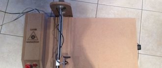
Assembling the interior
You can even make a laser engraver at home. To do this, you need to remove the stepper motors and guides from the printer. They will drive the laser.
The complete list of required parts is as follows:
- Laser diode from a writing drive.
- Radiator for diode.
- 3 stepper motors.
- 6 round guides.
- Fastenings for guides.
- 3 double or 6 single sliding carriages.
- Power supply 5 V, 4 A.
- Arduino UNO.
- 2 stepper motor drivers.
- 2 switches.
- Sheet of metal 50 x 50 cm and 2 mm thick (for the base).
- Large sheet of plywood.
- Corners for fastening plywood.
- Self-tapping screws.
- 2 furniture hinges.
- Wires with a cross section of 0.5 mm².
- Movable cable channel.
- Plastic cable ties.
- Transistor IRFZ44.
- 2 pressure rollers.
- 5 gears.
- Metal rod (axle for gears and rollers).
- 4 bearings.
- Toothed belt.
- 2 A step-down DC-DC converter.
- Four limit switches.
- Tact button.
- Jack 2.1 x 5.5 mm.
- 4 rubber or silicone feet.
- Thermally conductive adhesive.
- Epoxy resin with hardener.
Connection diagram for all components:
View from above:
Explanation of symbols:
- Semiconductor laser with heatsink.
- Carriage.
- X-axis guides.
- Pressure rollers.
- Stepper motor.
- Drive gear.
- Toothed belt.
- Guide fastenings.
- Gears.
- Stepper motors.
- Sheet metal base.
- Y axis guides.
- X-axis carriages.
- Toothed belts.
- Mounting supports.
- Limit switches.
Measure the length of the guides and divide them into two groups. The first will contain 4 short ones, the second - 2 long ones. Guides from the same group must be the same length.
Add 10 centimeters to the length of each group of guides and cut the base to the resulting dimensions. Bend U-shaped supports for fastenings from scraps and weld them to the base. Mark and drill holes for the bolts.
Drill a hole in the radiator and glue the laser in there using heat-conducting glue. Solder the wires and transistor to it. Bolt the radiator to the carriage.
Install the guide rail mounts onto the two supports and secure them with bolts. Insert the Y-axis guides into the mounts, put the X-axis carriages on their free ends. Insert the remaining guides with the laser head installed on them. Place the fasteners on the Y-axis guides and screw them to the supports.
Drill holes in the places where the electric motors and gear axles are mounted. Reinstall the stepper motors and place the drive gears on their shafts. Insert pre-cut axles from a metal rod into the holes and secure them with epoxy glue. After it hardens, place the gears and pressure rollers with bearings inserted into them onto the axles.
Install the timing belts as shown in the diagram. Pull them tight before fastening. Check the mobility of the X-axis and laser head. They should move with little effort, rotating all the rollers and gears through the belts.
Connect wires to the laser, motors and end switches and tie them together with zip ties. Place the resulting bundles in movable cable channels and secure them to the carriages.
Lead the ends of the wires out.
How to make a laser engraver from old printers with your own hands
Greetings to all readers of my instructions, as well as site visitors. Today I will tell you how to make a laser engraving machine from garbage. By junk I mean old printers. The kind of printers for which you can’t even find cartridges anymore. Copiers and MFPs are also suitable. The main requirement is the presence of stepper motors and polished shafts inside. A little later I will tell you in more detail which technique will suit us.
We will also make the base from scrap materials. Namely, plywood, OSB panels, construction fasteners. Everything will be controlled by Arduino. Arduino is the most affordable and easiest to program electronics that can be used for a CNC machine.
Therefore, the choice fell on this platform. It will be possible to use a combination of Arduino Uno and CNC Shield v3 or Arduino Nano and CNC Shield v4. Enough chatter, let's move on to the list of essentials
: - Arduino Uno or Arduino Nano - CNC Shield v3 (for Arduino Uno) or CNC Shield v4 (for Arduino Nano) - A4988 stepper motor drivers, 2 pcs.
(better with cooling radiators) - If the laser is 5V, the voltage stabilizer is 5V 7805 - TIP 120 or TIP 122 - 12V power supply - 3 mm plywood - 6 or 10 mm plywood (or OSB panel) - Ancient printers - Laser, better together with the driver - Rolling bearings with an internal diameter of 5 mm. — Connecting nut M5-10 — Cooling radiator — Construction pin 5 mm — Wood drills 5, 6, 7, 8, 16 mm — Jigsaw — Soldering iron, solder, rosin, flux, etc. for soldering — Wires Selecting and preparing a laser
The main part Our machine will, of course, have a laser. And everything is simple here. The more powerful the laser, the more different materials you can engrave. I made my laser from a laser housing ordered from AliExpress and a red LED from a DVD burner. If you follow my path, here are tips for choosing a drive. The drive must be a DVD-RW writer. The higher the recording speed, the more powerful the laser inside will be. Making a laser in this way is a long and painful process.
In simplified form, the diagram will look like this
The power of such a laser is not enough for much. It's best to order something already prepared. And it is better to choose a 12V laser. And take it immediately with the driver. This way you will deprive yourself of a lot of problems. Motors and electronics will run on 12V. If the laser is 12V, and also has a driver, it will be easy to connect it to the machine. Power can be supplied directly from the power supply. And the control wire (TTL) is directly connected to the Arduino CNC Shield.
If you, like me, have a 5V laser, and even without a driver, we’ll go the hard way. The laser will be powered by 5V and turned on via a transistor. Let's start the calculations. The 5V 7805 power stabilizer can withstand a maximum of 1.5 A. If the laser is more powerful, you will need to use two such stabilizers connected in parallel. So we will increase the maximum permissible current to 3A. Take the radiator:
To screw the stabilizer to it without shorting anything, we need insulators:
And also plastic washers for screwing stabilizers:
Stabilizer connection diagram:
We attach the voltage stabilizer 7805 to the radiator. Don't forget about the insulator and plastic washer:
If your laser is not powerful and 1.5 A is enough for it, one stabilizer will be enough. In this case, we attach a TIP 120 or TIP 122 transistor to the same radiator:
If your laser is more powerful, you should include a second voltage regulator 7805 in the circuit, connected in parallel with the first. In this case, the load will be distributed evenly across two stabilizers and the maximum current will reach 3A. The TIP 122 transistor allows you to control a load of up to 5A, so one is enough. We attach everything to the radiator:
To reduce problems and work, I recommend ordering a ready-made laser with a housing and driver. It will be more expensive, of course, but the machine will also be better. The DVD laser can be used to engrave plastic as much as possible. It can also burn plywood, but only at a very low speed, and in some places it leaves gaps. The quality of the engraving suffers.
To avoid problems with soldering homemade circuits and not to be disappointed in a laser engraver, take a 5-40 W laser. Even a 5 Watt laser cuts plywood perfectly!