How a drainage system project is created
It is advisable to develop a drainage system design at the stage of site development, since surface and groundwater can have a destructive effect both on green spaces on the site and on buildings. This approach will allow us to effectively and comprehensively solve the problem of flooding and avoid unnecessary financial and labor costs. But our company’s employees can carry out drainage even after construction. It will just take longer and, accordingly, will cost a little more.
The design of drainage systems in our company is regulated by the relevant regulatory documents - SNiP 2.06.15-85 and 2.04.03-85 and is based on modern developments of such organizations as Mosproekt, Research Institute Mosstroy, etc. in the field of drainage from polyethylene pipes with a filter shell.
Information you need to work on your drainage project:
- Site plan with buildings marked on it and indicating the depth of foundations
- Topographic survey of the territory (for complex reliefs or complex geoplastics - mandatory, for flat areas with simple relief - optional)
- A landscaping map (denroplan) is necessary to link the drainage system to the planned landscaping areas
- A road and path plan is needed in any case (for the effective collection and drainage of water from paths and solid paving areas)
- Geological and hydrological data of the developed area. This data may not be needed if the building site on which the site is located has already been studied and the soil has the same structure. Those. There is no need to re-order “geology”.
- Communication plan for the territory (existing and planned).
Types of drainage used in drainage system projects
Extract from SNiP 2.06. 15-85 (clause 3.23 “Engineering protection of the territory from flooding and flooding”): “When choosing systems of drainage structures, the shape and size of the territory requiring drainage, the nature of groundwater movement, geological structure, filtration properties and capacitive characteristics of aquifers must be taken into account , the area of distribution of aquifers, taking into account the conditions of recharge and discharge of groundwater, the quantitative values of the components of the groundwater balance were determined, a forecast was made for the rise of the groundwater level and its reduction during the implementation of protective measures.”
Drainage systems used today are classified according to many criteria - by landscape architecture objects, by target orientation, by design, by principle of operation, by materials used, by hydrogeological conditions and soil properties. Here are just a few of them, the most relevant for drainage of plots for private households.
According to the design of the watercourse, drainage can be:
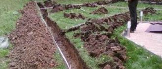
Open (cavitary)
– the simplest to implement. Along the perimeter of the site, trenches are dug with a depth of 0.6-0.7 m and a width of 0.5 with the walls deviating from the vertical to the outside by 30°. Open drainages serve to collect and redirect melt and rainwater in areas located on slopes.
Backfill (cavity with filler)
— it is arranged as follows: the bottom and walls of the trench are lined with geotextile, which acts as an additional filter material and prevents silting of the drainage. Geotextiles are laid out so that they protrude 30 centimeters on each side of the ditch. Then half the trench is filled with broken bricks and large crushed stone, after which finer material is poured almost to the top. The filling of the ditch is covered with the edges of geotextiles, soil is poured on top and turf is laid.
Closed (tubular)
- differs from backfill in that in a ditch, on a prepared bed of sand and crushed stone, drainage pipes are laid at a certain slope. Then a water-carrying layer of sand and crushed stone is created on top of the pipes. Geotextiles are used as in the previous case. The scheme of a closed-type drainage system is usually made in the form of a “herringbone” (there may be other configurations). Water from the side channels flows into the central one and is discharged to the water discharge point.
According to the principle of operation, drainages are distinguished:
- systematic
(evenly distributed throughout the site) - selective
(the drainage system is laid selectively for individual sections of the territory) - cut off
(head) - to intercept and redirect groundwater that comes from outside (for example, during flooding).
According to soil and hydrogeological conditions:
- horizontal drainage
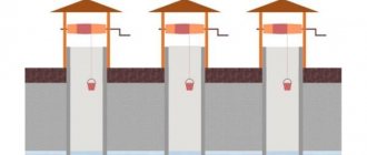
- differs in that the drains are laid horizontally with a calculated slope towards the discharge of water - vertical drainage
- is a system of wells and boreholes.
By types of landscape architecture objects:
- double drainage
- installed in areas where a high density of trees and shrubs is planned, due to which repair of the system in the future will be difficult - coastal drainage
– carried out in river floodplains - wall drainage
- to drain water from the walls and foundation of a building - reservoir drainage
- used in cases where water accumulates under a site or structure.
SNiP: drainage, rules for its construction, drafting
You are here: Add to bookmarks Printable version
For any construction process, it is very important to comply with the rules and established standards. According to the requirements of SNiP, drainage must be located at a certain distance from the building, and its device must meet all technical standards.
What is SNiP?
SNiP is an abbreviation derived from “Building Norms and Rules”. According to these codes, the requirements of various organizations for the implementation of sewerage, drainage, various buildings and other engineering structures are determined. SNiP takes into account ergonomic, economic, architectural, and technical characteristics that must be met.
Drainage project according to SNiP
Why comply with SNiP if sewerage, drainage or any other communication works like this:
- Any construction must be legalized, be it the construction of an extension near the house or the installation of a sewer pipeline. If you did not comply with the standards stated in the regulatory document, then the project will not be legal. Government organizations can force you to rebuild the pipeline or even fine you;
- SNiP not only helps to build drainage systems correctly, but also contributes to certain savings. The document identifies many ready-made solutions for drainage design that are least expensive for the owner;
- Communication carried out according to certain standards is more effective and durable. It is less susceptible to the negative effects of groundwater, seal failure or other factors.
What should be in the project
Before starting any construction, it is necessary to develop a drawing. According to the requirements of SNiP, the foundation drainage project must include:
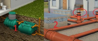
- Scheme of wells, location of drains (pipes), insulation;
Installation of a septic tank in accordance with the requirements of snip - Geometric data on the drainage system: ditch slope, trench dimensions, distances between prefabricated parts of the system;
- The diameter of the pipe used, the dimensions of the wells;
- Mounting materials used.
An example drawing of a drainage system made of concrete slabs
The resulting diagram will help to calculate the materials used, develop an estimate and approve the project in certain government agencies. In addition, according to SNiP, wall drainage of the foundation also takes into account the general slope of the site, the amount of average annual precipitation, the level of freezing of the earth and groundwater.
Basement drainage drawing
The next step is to install drainage according to the diagram . Regardless of whether a closed or open drainage system is used, the following operations must be performed before installing the drain:
- Clear the area of land where the drainage will be located. It is necessary to remove construction debris and stones that can damage pipes, remove plantings with large roots and ensure that tree roots do not break through the trench;
- The minimum depth of the trench is the maximum depth of soil freezing. Ideally, you need to make a ditch so deep that its bottom is slightly below the freezing level. If you ignore this rule, then in the cold season the drain will freeze and will not have time to thaw in the spring. Subsequently, the functionality of the drainage systems will be impaired;
- The walls of the deep drain must be strengthened and insulated. Sometimes craftsmen use geotextiles to insulate pipes directly, but in the northern regions it is much more convenient to install insulation in a ditch;
- A closed-type drainage system must combine several types of crushed stone of different fraction sizes. To backfill the lower level, a stone of large diameter is used, its size gradually decreases as it approaches the surface of the earth;
- The pipe is laid only on a sand cushion; this is necessary to form a kind of filter at the bottom of the ditch that does not allow water to pass through;
- Underground drainage can be a complex system consisting of numerous drains and highways or a simpler, perimeter one.
The first is used on large swampy areas of land, while the second is necessary to drain the foundation and is placed around the house; Wall drainage diagram - The permissible level of drainage depends on the groundwater level. But you need to take into account that the drainage ditch should be located at the lowest point of the site;
- In this case, the drainage well or septic tank is located even lower than the ditch, at an angle of at least 20 degrees;
- If you are installing a wastewater drainage system on the surface, then you must have an air conditioner. It is most often a metal mesh that filters rain or melt water from leaves and other debris;
- After completing all construction work, it is necessary to fill the trench for safety reasons. If external drains are used, and an open canvas should remain on the surface, then walkways or other floors must be installed. For a drainage system with a depth of 1 meter or more, soil backfill is used. To do this, the earth is sifted and heaped onto the ditch;
- SNiP allows the installation of drainage around the house at a distance of 1.5–2 meters from the outer wall of the building.
Geometric design
Installation of the drainage system is also carried out according to certain rules. The design of the system is controlled not only by SNiP, but also by GOST 1839-80. What is stated in the standards:
- The minimum level of horizontal drainage depends on the groundwater level, but by definition the depth is in the range of 70–150 centimeters;
- The width of the trench should be between 25–50 cm;
- The drainage must be laid along a slope.
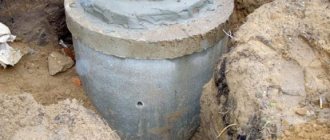
Please note that the trench also has a certain slope - 2 centimeters for every meter; Example of drain installation - To account for the difference in wastewater and control the operation of the drainage system, it is necessary to install septic tanks. These are wells that are installed at the lowest point of the drainage system. They can be closed or open, and made of polypropylene, concrete rings, metal, etc.;
- Afterwards, insulation (film, textiles, geotextiles, brushwood) is installed at the bottom of the trench, and pipes are installed;
Insulation of drainage - The ditch is sprinkled on top, the soil is compacted and the drainage system is ready for use.
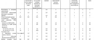
When installing drainage, the location of other communications must also be taken into account. With a permissible pipe height of 50 mm, the distance between the underground electrical network wire (if any) or the sewer system must be about 150 mm.
Drainage system design
The design of the system begins with geodetic and hydrological calculations of the site. This work is done to determine operating conditions, as well as the structure of the drainage system, as well as its key indicators.
The project must contain:
- Diagrams and technical drawings of the sewerage system and all its components, both on the surface and underground parts
- Installation properties of drainage systems - diameters, dimensions, installation depth and slope of the drainage pipe. SNiP gives standards for these values
- Dimensions of all components that make up the network - manholes, connectors, fittings and other parts
- Technical and economic budget for the construction of drainage systems
The project documentation must include the following specifics:
- Geomorphology of this site
- Features of the climate of the territory in which it is located
- Groundwater level markers
- Characteristics and structure of soils
- Distance of water bodies from the construction site
Construction of drainage trenches: structure overview
As you can see, both SNiP and “folk” craftsmen recommend equipping a foundation drainage system only with the help of trenches. Therefore, below in the text we will consider the construction of a drainage pit.
Foundation trench
The foundation trench is formed by the wall of the foundation itself and the slope of the foundation pit. It is filled with two types of soil - a permeable sand-gravel mixture and ordinary sand selected during the construction of the pit.
Moreover, permeable (drainage) soil is laid closer to the foundation wall, fixing it with the ballast method. As a result, the layers in the foundation trench are separated vertically.
Well, at the bottom of such a trench there is a layer of crushed stone (with a drainage pipe inside) and a layer of permeable soil.
The bypass trench is dug separately. It is buried half a meter below the base and filled with horizontal layers - 50 centimeters of crushed stone (with a drainage pipe inside), a layer of geotextile (protection from silting of the pipe) and a layer of sand (to the very zero level).
The upper part of such a drainage system is not protected, which allows the use of a bypass drainage system to also remove atmospheric moisture (and high water).
Existing technologies for installing a drainage system
Scheme of closed drainage on the site.
The need for drainage is quite easy to determine. It is needed when the soil on the site consists of clay and various types of loam. After rains, large puddles form in the area. In this case, the terrain of the site can be either flat (water has nowhere to flow) or inclined and located at the bottom (water flows into it from the top point of the site). In both cases, you simply cannot do without a drainage system.
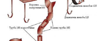
To carry out the work of creating a drainage system we will need:
- pipes;
- couplings;
- fitting;
- wheelbarrow;
- 2 shovels: shovel and bayonet;
- hacksaw;
- roulette;
- level;
- rail;
- tamping;
- sand;
- crushed stone;
- gravel (fraction 2-4 cm);
- geotextiles.
Drainage systems are divided into 3 main types: open, closed and backfill. The simplest is an open system. Its structure is as follows. A ditch 70 cm deep and approximately 50 cm wide is dug along the perimeter of the site. The slope of the ditch wall should be 30 º. All the water flows out of it through drainage systems into a large drainage ditch that serves several areas at once. This method of drainage is very effective during snow melt in the spring and heavy rains in the fall.
Higher up the slope, a transverse interception ditch should be dug. It collects water flowing from the upper part of the site. From its two ends, drainage channels extend downwards at an angle, connected to a large common drainage ditch.
Sectional diagram of the drainage system.
The open drainage method is an acceptable option only for areas with a small area and a uniform topography. If the area is large and, in addition, characterized by different heights (sometimes with slopes in different directions), then it will be necessary to equip a closed or backfill drainage system.
Both systems are quite similar in technology. The only difference: a closed drainage system involves laying special perforated pipes in the ditches. With backfill technology, broken bricks or large crushed stone are poured into ditches, on top of which a layer of finer gravel or soil is laid. Water is filtered through the filler. It goes in a given direction along the clay outlet.
Project Creation Basics
Design is the initial stage in any work. This directly applies to the creation of a drainage system.
Wall drainage diagram.
When designing a drainage system, the following factors are taken into account:
- level of resistance of soil rocks to the process of washing out particles;
- permeability indicator of individual rocks;
- the presence of tectonic disturbances on the site;
- composition of groundwater;
- location of sources recharging groundwater and their intensity.
The drainage plan must comply with the provisions of current regulations. The main requirements are:
- the size of the slope from the top point of the pipeline to the drainage structures is 0.5-0.7%;
- the presence of elements that control the functioning of the system and flush it;
- the bottom of the pipe is located 20 cm below the foundation level (if the drainage is close to the house)
If possible, the plan should include the installation of inspection wells. They should be installed in places where the pipe turns.
Calculation and design
In order for the drainage installed on the land to function correctly and have the necessary throughput capacity, before starting work, you need to draw up a drainage system design.
This is technical documentation, which is compiled taking into account generally accepted requirements and SNiP standards.
Design begins with hydraulic drainage calculations. They will help determine the amount of material required for the work, as well as its characteristics.
During the calculations you need to determine:
- the degree of permeability of all rocks that make up the soil on the site, as well as the tendency of hard rocks present in this area to crack;
- indicators of rock resistance to leaching of mineral particles, which can provoke soil salinization;
- the presence of tectonic disturbances in the area, the quality of the rocks on it;
- the average amount of precipitation falling in a given climate zone over a certain period of time;
- level and composition of groundwater at the site;
- features of the location and activity of groundwater sources.
Hydraulic calculation of drainage
Of course, if we are talking about a private plot, then a drainage project in such cases is not always done; usually the standard system diagram is taken as a basis.
But, if there are special climatic or geological conditions here, the project is still needed.
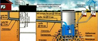
Site drainage scheme
In addition to the above calculations, it is imperative to examine the topography of the site. Determine the location where the largest amount of water accumulates after rain or melting snow. This will help to correctly determine the slope of the drainage system elements and make it more efficient.
Now you can begin to design a drainage system for the site.
It will include:
Site drainage system design
- a schematic sketch of the laying of drainage pipes for the arrangement of deep and surface communications;
- design parameters of drainage pipes: length, cross-sectional diameter, slope, laying depth, as well as the distance between several drains;
- dimensions and location of other elements of the drainage system: connecting nodes, wells, water receivers;
- a list of materials that will be required to create an effective drainage system.
Landscape design for drainage
Having a project in hand, it will be easier to determine the required volume of material, as well as perform installation work.
SP drainage systems
Design of external sewerage, gutters and drainages
6.1.1 The selection of pipes should be made taking into account the composition of the wastewater, its temperature, based on hydraulic and strength calculations.
6.1.2 For gravity sewerage, sewer pipes should be used. The use of pressure pipes must be justified.
6.2.1 For non-pressure sewerage, smooth pipes are standardized in outer diameters, except for pipes made of glass and basalt plastics manufactured by winding.
Pipes are divided into classes according to the ring rigidity of the shell: flexible, semi-rigid and rigid. The class of pipes is given in Appendix A.
6.3.1 Gravity sewerage pipelines should be provided with both detachable and permanent connections.
6.3.2 As detachable connections, socket connections should be used, sealed with rings of various profiles.
6.3.3 The main types and methods of pipe connections are given in section 3.3.
6.3.4 For sewage pressure pipelines, predominantly permanent connections should be used - gluing and welding.
6.3.5 Detachable connections (flange, etc.) on pressure sewers are usually used to connect pipes to equipment.
6.4.1 The routing of external sewerage must be carried out taking into account the requirements of SNiP 2.04.03.
6.4.2 Gravity sewerage pipelines should only be straight. Changing the diameter of the pipeline and its direction is allowed only in wells.
Pressure sewer systems are performed in accordance with section 5.
Calculation of gravity pipelines for strength should be carried out according to the method given in Appendix D.
Hydraulic calculations of gravity underground sewerage pipelines are carried out according to the formulas given in section 4.5.
6.7.1 The need to compensate for thermal elongation of pipes in pressure sewers is established by calculation in accordance with Section 3.7 of this Code of Practice, taking into account the pinching effect of the soil.
When the pipeline is pinched by soil, the elongation of the pipeline decreases. The amount of decrease in D lum is determined by the formula
where f
t is the coefficient of friction of the material on the soil, determined experimentally; in the absence of data, it can be approximately taken equal to 0.4,
g - volumetric weight of soil, N/m 3,
H
— depth of pipeline, m,
L
— pipeline length, m,
E
szh is the elastic modulus of the material in the direction of deformation, Pa,
s
— pipeline wall thickness, m,
Ky is the soil compaction coefficient, taken equal to 1 for a degree of compaction of 0.95 and 0.5 for an uncontrolled degree of compaction when backfilling a trench.
6.7.2 Compensation for temperature deformations of pipelines in gravity sewers is provided by:
- socket joints sealed with rings,
- partially in sewer wells by constructing a passage through the walls of the well and filling the tray.
6.8.1 For drainage systems, it is allowed to use sewer, drainage and water intake wells made of: polymeric materials (PE, PVC, etc.), combined (elements made of polymeric materials in combination with elements made of reinforced concrete), reinforced concrete and brick. The dimensions of the wells must correspond to those specified in SNiP 2.04.03.
6.8.2 Wells made of polymer materials should be used in conjunction with a protective slab made of reinforced concrete and traditional metal hatch elements.
6.8.3 The tray part of manholes made of polymeric materials must have ready-made trays made of polymeric materials, as well as protruding pipes for connecting the pipeline.
Is wall drainage around the house really necessary? Construction nuances
Wall drainage is arranged to drain rain, melt and ground water (rising during flood periods) from the foundation. When is its installation necessary, and when can you do without building a drainage system around the house? Features of wall drainage, project preparation.
Wall drainage device
Schematically, the drainage system near the foundation can be designated as follows:
- a closed network of perforated pipes around the house, made with a single slope towards the lowest point,
- where the prefabricated well is installed,
- from there the water leaves the site,
- inspection and cleaning of the system is carried out through inspection wells installed at every second bend.
Of course, during the construction of a building, the foundation is protected with waterproofing materials. But even with the highest quality, the destructive effects of excess liquid will appear after five years. And it is better to prevent this negative moment. Using foundation wall drainage.
When is its construction obligatory?
To answer this question, a hydrogeological map of the site is needed. Surveys are carried out at a depth of three to four meters. The composition of the soil is studied, topographic surveys are carried out, and the location of buildings on the site is planned.
SNiP for wall foundation drainage names the following conditions:
- basement floors, technical undergrounds, intra-block collectors, communication channels are located below the groundwater level or the distance from the floor to groundwater is less than fifty centimeters,
- basement floors, technical undergrounds, intra-quarter collectors, communication channels are located in clay and loamy soils (the groundwater level is not important in this situation).
In the first case, wall drainage will protect the basements and foundation from the seasonal rise of groundwater. In the second - from seasonal swelling of the soil (clays and loams do not conduct moisture well, water accumulated in the soil in autumn freezes in winter).
Ways to protect the foundation from moisture
The drainage system around the building is arranged in two ways:
1. Surface drainage.
Today, more and more people prefer a deep system that is hidden from human eyes and does not violate the design. The area above the drainage can be used for planting plants and creating flower beds.
Wall drainage section:
A closed drainage network is a continuous pipeline covered with a sand and gravel mixture. The pipes have perforations and stiffening ribs, due to which the strength margin in the cross section increases.
When designing wall drainage, a number of conditions must be observed:
1. Drainage pipes are laid with a slope of one and a half to two centimeters per linear meter. The direction of the slope along the entire perimeter is the same - towards the lowest point, collection well or collector.
2. The optimal distance between inspection wells on a straight section of the pipeline is forty meters.
3. Drainage structural elements must be below the soil freezing level.
4. Drains are laid at a distance of three or more meters from the foundation.
When drawing up a wall drainage diagram, calculate the slope and diameter of the drains. The throughput of the entire system depends on this.
Wall foundation drainage SNIP
- 4169
- foundation waterproofing drainage foundation drainage
The most harmful phenomenon for the foundation is groundwater and melt water.
Because of them, during the snowmelt season, flooding occurs, the walls of the base become damp, and become covered with mold.
Through capillaries, water rises through the concrete layer to other structures of the house, destroying them too.
To protect the building from these factors, it is necessary to install a drainage system for drainage from the foundations of buildings.
Wall drainage as the most effective way to protect the foundation from groundwater
The arrangement of life in a private city house or in a country cottage does not stop with the construction of a residential building.
The foundation of the house requires additional protection, since over time the destructive effects of groundwater become noticeable.
One of the effective preventive measures is the installation of a drainage system - a complex structure, the main task of which is to collect and move liquid in the ground.
Let's try to find out who can do without drainage and whether it is possible to make drainage around the foundation with your own hands.