The water cycle in nature and precipitation
As a result of the action of solar energy, water constantly evaporates from the earth's surface.
The largest amount of moisture on the globe evaporates from the surface of the seas and oceans (88%) and much less (12%) from the surface of the land. Evaporated moisture is transported by air currents. When it encounters cold air currents, it condenses and falls onto the surface of the ocean or land in the form of rain and snow. Precipitation that falls on the surface of the land partially evaporates, partially seeps into the ground, and the rest of the precipitation flows down the slopes to the lowest places on the surface, feeding streams, rivers and large rivers, which carry this flow back into the seas and oceans. When the closed cycle of moisture movement (ocean - atmosphere - ocean) is incomplete, a small water cycle occurs in nature. With a complete closed cycle (ocean - atmosphere - land - ocean), a complete water cycle occurs in nature (Fig. 1). Areas in which the entire amount of precipitation evaporates (there is no runoff) are called drainage-free areas (deserts, semi-deserts). With constant circular circulation of water between land and ocean, the total amount of precipitation X falling on the land surface is equal to the amount of evaporation losses Z, underground runoff Y1 and surface runoff Y2. The water balance equation can be expressed by the formula X = Z + Y1 + Y2
Or, taking the total drain Y = Y1 + Y2
X = Z + Y
Fig.1. Scheme of circular circulation of water in nature
1-evaporation from the ocean surface; 2 - precipitation falling into the ocean; 3—precipitation falling on land; 4 - evaporation from the land surface; 5 - infiltration; 6 - underground drainage; 7 - river flow into the ocean
In our country there is a positive water balance: i.e. the average annual precipitation exceeds the average annual amount of moisture evaporation. This is confirmed by the presence in the country of a developed network of large and small rivers and their tributaries, i.e. there is a constant river flow from the land surface. The exception is certain arid areas, where the average annual amount of precipitation is less than the average annual amount of moisture evaporation from the land surface.
A number of conditions contribute to the acceleration of the formation of water droplets in the atmosphere, of which it should be noted that the air basin is clogged with combustion products emitted into the air by pipes of industrial enterprises, as well as urban dust. Observations have established that short intense showers often occur over industrial areas and the centers of large cities, while in suburban and nearby rural areas no precipitation is observed at this time.
The amount of precipitation falling on the soil surface is measured in linear and volumetric units. In linear units, the average annual and average monthly amount of precipitation H, mm, characteristic of a given climatic region, as well as the intensity of individual rains i, mm/min are measured. In technical calculations, the volumetric unit of measurement of the amount of precipitation g expressed in l/s per 1 hectare is used. To move from one unit of measurement to another, use a dependency
g = ki
where: k = 166.7 - volumetric conversion factor, i.e. volume of precipitation, l/s, falling on an area of 1 hectare with rain intensity of 1 mm/min; k =0.001·10000·1000/60= 166.7 l/s per 1 ha, here 0.001 is the height of the sediment layer, m; 10,000 - area of 1 hectare, expressed in m; 1000 - volume of 1 m, expressed in l; 60 is the number of seconds in 1 minute.
The characteristics of the rainfall are recorded by recording instruments - rain gauges, which mark the height of the layer of precipitation h, mm, that fell over a period of time t, min. The amount of precipitation falling per unit time determines the intensity of rain. Average rain intensity, mm/min,
i=h/t
Each rain is characterized by intensity (i or g), the amount of precipitation that fell per unit of time, the duration of the rain and the probability of its occurrence, i.e. the probability of recurrence of such rain over a given observation period of years. In practice, when calculating a storm sewer network, the probability of recurrence of rain intensity of a given duration is taken as c = 1 year, c = 3 years, c = 5 years, c = 10 years, even more rare repetition.
There is a certain relationship between the intensity of rain and its duration, which is expressed by the formula
g = A/tn
g—rain intensity, l/s per 1 ha; t—rain duration period, min; A and n are parameters depending on the climatic region of the settlement and the accepted period c.
From the above dependence it follows that longer rains have lower intensity, and vice versa.
Atmospheric precipitation affects the operating conditions and improvement of urban areas. The total amount of precipitation falling on the earth's surface during the year varies widely. The largest amount of precipitation on the globe was recorded in Cherrapunji (India, Assam state): the average long-term annual amount here was 11,013 mm, the maximum per year was 16,305 mm (1899) and 24,326 mm (1947). In the central part of the European territory of Russia, the average annual precipitation gradually decreases when moving from west to east. Near the western borders of Russia, the average annual precipitation reaches 650-700 mm per year, gradually decreasing eastward to 500-400 mm per year. On the western slopes of the Ural ridge, the average annual precipitation increases again to 600-700 mm per year.
In the Far East, a decrease in precipitation occurs from the Pacific coast to the eastern slopes of the Ural Mountains. The greatest amount of precipitation per year in Russia falls on the eastern shore of the Black Sea, as well as in the Altai Mountains, on the slopes facing the Pacific Ocean. In the Altai mountains, the influence of a barrier that has arisen is felt - high mountains in the path of the movement of winds carrying large reserves of moisture from the ocean.
Formation of surface runoff and its organization
The formation of surface runoff depends on the terrain conditions, and the flow rate depends on the size of the catchment area of the basin and the nature of the use of its territory.
The boundaries of the drainage area of the basin are determined on a topographic plan, taking into account the terrain, and they are drawn along watershed ridges located at the intersection of two slopes, one of which faces the main thalweg of a specific drainage area. The main thalweg of the basin has access to larger thalwegs, streams and rivers. Storm runoff and spring snowmelt runoff are formed within the drainage area. In urban planning practice, the organization of surface runoff is considered within relatively small catchment areas (300, 500, 1000 hectares), in which the largest costs will be generated by storm runoff. In an undeveloped area located in natural runoff conditions, the main directions for drainage of surface runoff will be the thalwegs of small basins. In the process of development and improvement of urban areas, the natural drainage system is disrupted. Instead, an organized closed drainage system is created.
The main collector of the pool is located in a strip free from urban development, i.e. within the “red lines” and streets or a technical strip specially allocated for these purposes, which is located in the direction of the main thalweg (Fig. 2). This condition must be taken into account in the planning and development of urban areas. At the same time, favorable conditions are created for the placement of main underground utility lines (storm and fecal sewerage, etc.).
To drain surface runoff from the side slopes of the pool, a lateral network of drains is designed in accordance with the street layout.
Fig.2. Scheme of an organized (closed) drainage system
1 - main reservoir of the pool; 2 - lateral network; 3 - inspection wells; 4 - rainwater wells; 5 - watershed line; 6 — designed ditches; 7 - existing thalweg in an undeveloped area
The organizing drainage system is the trays of intra-block driveways and city streets, ensuring the flow of surface runoff into a closed storm sewer network. In the practice of planning and development of urban areas, there are various cases of the formation of surface runoff; the conditions of formation depend on the size of the developed area and the nature of its use.
First case. Surface runoff is formed within the completely built-up catchment area of the basin. At the same time, natural drains (streams and small rivers), flowing and stagnant reservoirs (ponds) located within the built-up area are abolished. Polluted surface runoff coming from built-up and landscaped areas can no longer be used to feed open watercourses and reservoirs. In place of the abolished natural drainage system, a closed network of urban storm sewerage is being installed, which should ensure the removal of surface runoff from the area of residential neighborhoods, as well as intra-block and city passages.
Surface runoff from a closed storm sewer network is released into flowing watercourses (rivers) or special coastal canals, which divert the surface runoff for clarification outside the urban area into a system of technical reservoirs and settling tanks, from which the clarified runoff enters the rivers (Fig. 3).
Second case. Surface runoff is formed within a large drainage area, significantly larger than the area of the built-up area. In this case, the lower part of the pool is used for development, and its upper part remains in natural conditions.
According to the conditions for the formation of surface runoff, the total drainage area of the basin can be divided into two private areas - F1 and F2 (Fig. 4). Within the catchment area F1, runoff is formed under natural surface conditions. Within the F2 catchment area, surface runoff is formed within the built-up urban area, which corresponds to the first case (see Fig. 4). The runoff generated within the catchment area F1, which is located in a suburban environment, will flow along the natural thalweg of the basin to the border of urban development, and then through the urban area it is passed through an underground collector to the point of release into a flowing watercourse (river). The cross-section of the city collector must ensure the passage of the calculated flow rate coming from the drainage area of the basin F1 and the flow rate generated within the development area of the F1 territory.
Fig.3. Scheme of organization of surface runoff within a built-up area
1 - city border; 2 - main boundary of the basin; 3 - watershed ridge; 4 - main reservoir of the pool; 5 - coastal channel; 6 - technical settling ponds; 7 - emergency spillways
To reduce the cross-sectional dimensions of the city collector in the thalweg of the basin at the boundaries of urban development, it is advisable to provide for the installation of a regulating tank - a reservoir. In terms of planning, such a reservoir is used for various purposes (boating, sport fishing, etc.), including as a container for accumulating surface runoff formed in suburban conditions on area F. Dimensions of the reservoir area, water surface marks and the edges of the slope and bank are determined taking into account the use of the reservoir as a regulating tank.
Fig.4. Scheme of organization of surface runoff in a built-up lower part of the basin; the upper part of the pool is preserved in natural conditions
1 - city border; 2 - main boundary of the basin; 3 - watershed ridge; 4 - main thalweg of the basin; 5 - den; 6 - bypass drain; 7 — designed regulating capacity; 8—private boundary of the basin; 9 - main reservoir of the pool; 10 - coastal collector; 11 - emergency spillway; 12 - technical settling ponds; F1 - undeveloped area of the pool; F2 - built-up area of the pool
Third case. Urban development retreats from the bank of the river to a considerable distance. There remains an undeveloped area between the river bank and the urban development boundary. Such conditions arise when the floodplain part of the river turns out to be unsuitable for urban construction: the coastal part is flooded with flood waters, the surface of the soil layer is swampy and has unfavorable geological conditions (peat, silt deposits). The organization and removal of surface runoff from a built-up urban area is carried out using a closed drainage system (as in the first case). Stormwater runoff from the head of the city sewer is passed through a combined drainage system consisting of an open drainage channel and a closed drainage pipe. The length of this path can be significantly longer compared to the length of the main city sewer (Fig. 5).
Fig.5. Scheme of organization of surface runoff with a built-up upper part of the basin
1 - city border; 2 - main boundary of the basin; 3 - watershed ridge; 4 - main reservoir of the pool; 5—private boundary of the basin; 6 - open channel; 7 - spillway collector; 8 - emergency spillway; F is the built-up area of the pool; F - undeveloped area of the pool
For the general improvement of the floodplain part of the territory, it is necessary to drain it with the installation of shallow drainage channels and an open drainage channel. Due to sanitary conditions, an open channel cannot be used to pass through contaminated storm drainage coming from the storm sewer network. To receive and remove surface runoff coming from urban areas, it is advisable to install an accompanying drainage collector located next to the open drainage channel. Thus, for complete engineering improvement of the floodplain part of the city, it is advisable to design a combined drainage system consisting of open and closed canals. For economic reasons, the cross-section of the drainage drain is designed taking into account the passage of constant costs entering the city drainage network (industrial iodine, runoff from street irrigation, drainage outlets, etc.), and rainwater is given only by frequent rains. During the period of rain floods, less frequent
repeatability, when the outlet drain overflows, the open channel and the outlet drain will work together.
In cities and towns, a closed drainage system is installed to drain surface runoff. For summer cottages, small villages and park areas, you can design an open drainage system consisting of concrete trays, ditches and reinforced drainage channels (Fig. 6). At street intersections and entrances to courtyards, ditches are replaced with shallow crossing pipes. The depth of the ditches should be no more than 0.8-1 m. The minimum width along the bottom of the ditch is 0.4 m
Fig.6. Scheme of an open drainage system
1 - cuvettes; 2 — moving pipes; 3 - inspection wells
The advantage of an open drainage system should be considered the ability to quickly install it at a low cost of money and building materials. However, such a system also has a number of significant disadvantages, the main of which are the need to install a large number of crossing pipes and bridges, as well as a decrease in the sanitary level in residential areas, especially with small slopes.
With an open drainage system, the width of the streets between the “red lines” in relation to the calculated width is increased by the width necessary to accommodate the ditches. Organized runoff from road gutters and intra-block driveways enters storm drainage wells. The length of the free path of the water flow from the watershed point to the first rainwater wells is taken to be 75-250 m, depending on the slopes of the road tray and the size of the drainage area in this drainage section. The filling height of the roadway trays should not exceed 8-10 cm with a side height of 15 cm. The amount of water passing through the tray depends on the filling of the tray and the slope along the road tray.
The storm sewer network consists of the main basin collector and connections to the side drainage network. The main collector of the pool is installed to replace the abolished thalweg of the pool. The main collector route is located within the “red lines” of a street, boulevard or technical strip allocated for laying main underground communications.
For operational reasons, it is advisable to locate the route of the storm sewer network outside the carriageway of the streets, so that when connecting the side network the road surface is not destroyed. For normal operation of the storm sewer network, inspection wells are installed at corners of turns, at points where the lateral network is connected, as well as at places where pipe sizes and slopes change. To receive organized runoff, rainwater wells are installed in road gutters and at street intersections. At the same time, they strive to create convenient conditions for the movement of pedestrians and vehicles, as well as to meet the requirements of the general improvement of the territory and the protection of city structures from the harmful effects of surface water.
The main attention should be paid to protecting street intersections, city and transport areas, as well as pedestrian routes from surface runoff. The distance between rainwater wells installed in road trays is on average 50-60 m. The layout of these wells at street intersections, depending on the direction of drainage, is shown in Fig. 7. In addition to rain and melt water, the closed storm sewer network accepts discharges of drainage water, as well as conditionally clean water (i.e., not requiring special treatment before being discharged into drains) from industrial enterprises in agreement with the sanitary inspection authorities.
Fig.7. Schemes for placing rainwater wells at street intersections
1 - rainwater wells; 2 - pedestrian crossings; 3 - flow directions
Possible problems and consequences of poor cleansing
The requirements for cleaning CBS are becoming stricter every year. As the volumes of waste fluid from human activities and production processes increase, the level of pollution also increases significantly. This negatively affects people's quality of life.
Inappropriate installation of treatment facilities leads to a number of negative consequences . Household wastewater ends up in water bodies, where the percentage of oxygen content decreases due to pollution. This leads to the proliferation of microorganisms, which negatively affects flora and fauna.
Important! With an abundance of organic substances in such water it becomes dangerous even to swim.
Gutter designs
With an open drainage system, cross-sections of streets are made taking into account the intended level of improvement of the urban area.
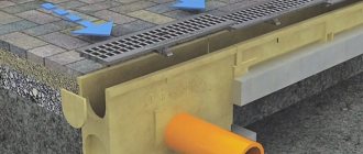
A typical cross-section of a road with shoulders and ditches is shown in Fig. 8. Surface runoff from the roadway, as well as from the adjacent territory, is diverted into ditches located along the roadway. Ditches are made of earthen ones with reinforcement of their slopes with stone or concrete slabs, as well as from ready-made reinforced concrete blocks with vertical walls.
Fig.8. Typical cross-section of a road with shoulders and ditches
1 - carriageway; 2 - roadside; 3 - earthen ditch
The total width of the street between the “red lines” is reduced (while maintaining the overall dimensions of the main elements of its division) due to the strip required for the construction of slope ditches of a general profile (Fig. 9).
Fig.9. Scheme of open drainage on roads with trays
1 - roadway; 2 - road flow; 3 - paved ditch; 4 - prefabricated reinforced concrete ditch; 5 — bypass tray; 6 — side stone
The dimensions of the main outlet channel with an open drainage system are determined by calculation. With improved types of road surfaces, a closed drainage system is installed - the ditches are replaced with reinforced concrete pipes and laid at a depth that ensures that the drains do not freeze (Fig. 10).
Fig. 10. Scheme of closed drainage on roads with improved surfaces
1 - rainwater well; 2 - inspection well; 3 - drainage pipe; 4 - outlet from the rainwater well; 5 — side stone
Surface water from the road trays flows into rainwater wells, the flow from which flows into the main network of drains. Stormwater and inspection wells are constructed from prefabricated reinforced concrete blocks. Their sizes are assigned based on the operating conditions of the network (Fig. 11, 12). For design reasons, prefabricated inspection wells are arranged in three types depending on the diameter of the pipes
Fig. 11. Scheme of rainwater well
1 - working chamber; 2 - bottom; 3 - sandy base; 4 - outlet from the rainwater well; 5 - sealing the hole with concrete; 6 - cast iron grate; 7 — side stone
On large collectors, special necks are installed on which cast iron hatches are installed. To lay a storm sewer network, round reinforced concrete pipes and prefabricated rectangular channels are used, and when installing large-sized collectors, atypical prefabricated structures are designed.
Fig. 12. Schemes of prefabricated inspection wells depending on the diameter of the pipes
a - 300-500 mm; b - 600-700 mm; c - 800-1100 mm; 1 - floor slab; 2 — neck ring; 3 - support ring; 4 — hatch with cover; 5 — hole for laying pipes; 6 - working chamber
When laying pipes of large diameter and their laying depth is insufficient, instead of one, two pipes of smaller diameter are laid, having the same total drainage capacity (Fig. 13).
Fig. 13. Scheme of laying two pipes side by side
1 - reinforced concrete pipe; 2 - concrete base; 3 - preparation from crushed stone
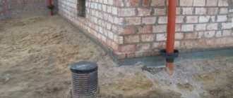
The minimum backfill above the top of the drain pipe structure is taken to be at least 1 m. Laying round pipes with sealing of quarter and socket joints is shown in Fig. 14.
Fig. 14. Scheme for laying a round pipe with sealing the socket joint and detail
1 - reinforced concrete pipe; 2 - concrete base; 3 - preparation from crushed stone; 4 - pipe bell
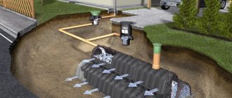
Operating principles of structures installed to clarify polluted surface runoff
The purpose of surface runoff clarification structures is to capture solid products and ether-soluble substances washed into the storm network from road and other surfaces located within the built-up area.
Solids from the runoff settle in sections of the settling tank. Ether-soluble substances (residues of petroleum products) are captured using a hydraulic seal and post-treatment filters, the design of which depends on the type of structure. Within large green areas, settling ponds are also installed, equipped with drainage structures with devices for catching residual oil products. Such settling ponds can simultaneously serve as containers for regulating surface runoff. The ponds are located on the main thalwegs of the drainage basins.
When operating structures constructed to clarify surface runoff, it is necessary to ensure timely removal of retained oil product residues from the surface of individual compartments, and solid sediment from the settling sections of structures. Lifting of solid waste and loading it into vehicles is carried out mechanically, and removal of oil products from the surface of individual compartments and draining them into storage tanks is carried out using a rotating slotted pipe mounted in the structure.
When constructing a structure for surface water treatment, it is necessary to allocate a place for the disposal of solid waste, and also to decide on the method of disposal of retained petroleum products. Without this, it is impossible to start operating the structure. For solid waste disposal, the remaining quarry openings or other areas are used, the runoff from which will not flow into open watercourses. The solution to this problem in each individual case will depend on local conditions and must be agreed with the sanitary authorities. If the remaining petroleum products cannot be disposed of, they are burned in special furnaces or subject to deep burial.
The constructed structure is equipped with access roads, which should ensure good operation of operational transport with designated areas for stopping fire trucks. To protect against pollution of the surrounding area and for fire-fighting purposes, the area allocated for the construction of treatment facilities is fenced with green spaces.
What it is
Domestic sewerage (also called “fecal”) is an extensive system of pipelines that provide the reception and disposal of wastewater in residential and public buildings in a city or other populated area. Every apartment, educational or medical institution, public or sports buildings, and facilities have a connection to this network.
When the question arises, what is household sewerage, what is it, it is necessary first of all to consider the types of existing systems. There are three of them:
- stormwater Provides removal, purification and discharge of rain or melt water;
- industrial. Serves enterprises that use water in the technological process;
- domestic sewerage. This is a system that removes human waste products in populated areas.
The difference between these networks lies in the composition of the wastewater. Industrial waste contains process components that often pose serious hazards. They can be poisonous, aggressive, and destructive to the environment. The combination of industrial waste with the main K1 system is allowed only after preliminary treatment and treatment of wastewater, carried out at the enterprise’s own treatment facilities.
Storm drains are considered as conditionally clean. In particular, it allows rainwater to be discharged into a reservoir without treatment. When considering the difference between household and storm sewer systems, this point is mentioned first. However, direct discharge is carried out only in emergency situations, when the volume of wastewater exceeds the capacity of the collector. This happens during heavy, prolonged downpours. Ordinary rainwater is always sent to treatment facilities, as it contains a large amount of pollutants - lubricants, petroleum products, and industrial waste.
Unlike industrial or stormwater networks, a sanitary sewer system receives wastewater from plumbing, kitchen, or laundry equipment. The receiving elements are directly connected to the outlet sets of appliances, washing machines or dishwashers. however, a considerable amount of waste comes from outside. Various liquids are poured into toilets, which may contain solid particles, chemical solutions and other components. Because of this, the composition of the K1 system wastewater is considered the most complex and requires multi-stage treatment. The design of urban WWTPs consists of large tanks where wastewater settles and undergoes multi-stage filtration before being discharged into a reservoir.