The term “storm drainage system SNiP” means a certain set of Construction Norms and Rules that regulate the construction of storm drainage systems at industrial and other facilities, on highways, and in residential areas. It is also highly advisable to adhere to SNiP when installing a storm drain (as storm drainage is sometimes abbreviated as) on private territory, even the smallest one.
Important! Violation of SNiP for storm drains can result not only in a large fine and the obligation to re-equip it properly, but also in low efficiency of the system.
What general provisions does SNiP storm drainage have?
SNiP for storm drainage numbered 2.04.01-85 provide standards that must be observed at all stages of construction: from design to direct operation.
SNiP - regulated standards that external sewer networks must comply with, contain formulas for carrying out calculations during design, indicate materials, pipe laying depths, etc.
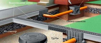
Today, such types of storm drains as point and linear are actively used. SNiP provides the most detailed requirements for the arrangement of a mainly linear type of sewerage system. The entire complex of such a system consists of a network of separate or interconnected channels located at a certain angle of inclination. They are designed to collect and drain rainwater and melt water to the appropriate collectors and reservoirs.
As a rule, linear sewerage is of a closed type. Rainwater receivers are connected by pipes dug into the ground, and they are connected to special collectors. Monitoring and maintenance of the system is carried out using inspection wells specially equipped for this purpose with a diameter of at least a meter.
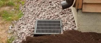
Point storm drainage, according to the document “Storm sewerage system SNiP”, is intended for point collection of water and its removal from the building to collectors. Water is collected by special rainwater inlets. It is mandatory that rainwater inlets have a protective cover, which prevents premature littering of the inlet basket and also ensures unimpeded passage for people and animals. The standards regulate the following elements of the storm sewer system:
- storm water inlet It is one of the main elements of the entire sewer system and serves to directly collect water;
- pallet. It also serves to collect rainwater and is installed at the entrance to the room;
- gutter or tray. These elements are installed in drainage channels. The channels must be located at a certain angle to the collector in order to ensure natural flow of water under the influence of gravity;
- pipeline. Designed in the same way as canals, for the natural drainage of water, but through pipes that go deep into the ground;
- sand trap. This device is designed to separate water from sand and other coarse debris;
- inspection (audit, inspection) well. Designed to inspect the network and monitor the water level in it.
In addition, the document “Storm drainage SNiP” helps to determine the volume of expected runoff in accordance with the terrain, the nature of the soil, etc.
Scheme of the roof part of the storm drain
After completing all the preparatory work, when the storm sewer diagram is prepared, you can begin the installation of the sewer system itself. The mains that are planned to be used to drain rainwater from the roof should be installed at an inclination of 2% relative to the length of the structure. Below we provide step-by-step installation instructions.
Installation of the roofing part
You need to start by installing rainwater receivers. For them, you need to drill holes, then install devices in them and secure them with mastic. After this, you will need to treat all resulting joints with silicone-based sealant.
Then you need to start hanging pipes, in the case of installing a point sewer system, or trays, if we are talking about a linear type.
After this, it is necessary to install water drainage pipes or risers, depending on which sewer system was chosen.
The last step will be the arrangement of a closed drainage of rainwater into a special collector. Some types of storm drainage systems require an open drainage system.
Installation work must be carried out using clamps that are fixed to wall structures or partitions. Marking must be carried out in advance, taking into account the angle of inclination.
Return to content
Stormwater system performance calculation
Despite the fact that SNiP for storm drains was approved 30 years ago, its relevance still remains. Based on its settings, you can easily determine what performance system needs to be installed in a particular location.
Storm drainage is the connection of pipes, stormwater inlets, gutters and other components into a single system that is used to capture and drain water from roofs, routes and sites.
In general, despite the apparent cumbersomeness and complexity of formulas and tables, it will not be particularly difficult for the owner of a private home or summer cottage to make simplified calculations. As a result, it will be possible to obtain data on such system parameters as:
- the degree of deepening of pipes into the soil;
- optimal pipe angle;
- as well as the volume of water that must be removed from the facility.
Storm drain performance can be calculated using the following formula: Q = q20 × F × Ψ. Here the variables are:
- Q is the final volume of water required for drainage;
- q20 is the coefficient of average precipitation volume. It is measured in liters per hectare and is unique to a particular area. The corresponding values of this coefficient are taken directly from the SNiP documentation;
- F – area of the site where the sewerage system is installed;
- Ψ is the coefficient of absorption of moisture by a particular surface (it is also simply a correction factor).
For Ψ, the following coefficients will be relevant: indicator 1.0 - for an ordinary roof of a house, that is, practically no absorption occurs; for asphalt – 0.95; for a surface such as a concrete coating, the correction factor will be already 0.85, and for crushed stone and gravel – 0.4. Finally, for open ground and lawns – 0.35.
Simply by multiplying all the data, you can get the total volume of liquid for one storm inlet under given conditions. As practice has shown, in the vast majority of cases, for private country land it will be enough to have pipes with a diameter of 10 to 11 cm, and in the case of a collector this value will increase to 20 cm.
When designing, it is also necessary to take into account the possibility of manual cleaning of pipes or under high pressure, for example, using a household car wash. This is only possible when the diameter of the pipes does not exceed 20 centimeters. Otherwise, it is impossible to do without the use of specialized equipment.
How to calculate the required angle of inclination
The standards in “Storm sewerage SNiP” also allow the owner to calculate the optimal angle of inclination of the pipe. After all, as you know, wastewater is transported in a storm drain, obeying the force of gravity, that is, naturally and without the use of any pumps or other mechanisms.
However, it is not always easy to determine exactly what angle is best to position the pipe to ensure smooth and even transport. Well, SNiP allows you to do this too. Mainly, it all depends on the diameter of the pipe. The calculation is made on the basis of a special table. But in most cases, the average owner can be guided by a simplified scheme:
- for a pipe with a diameter of up to 110 millimeters, a slope of 2 centimeters per linear meter of pipe will be sufficient;
- for pipes with a diameter of 150 millimeters - from 8 to 10 centimeters;
- for a sewer pipe with a diameter of 200 millimeters, a slope of 7 centimeters can be considered optimal;
- finally, for pipes with a diameter of 500 millimeters, the slope should be 30 millimeters per meter of pipe.
Stormwater systems are networks of canals that are needed to collect and transport water. According to the requirements of SNiP, storm sewers are installed so that there is a slope towards the main collector.
Directly in front of the sand trap, the slope should be slightly less in order to ensure uniform distribution of sand and liquid. Otherwise, the flows risk simply mixing with each other.
What SNiP says about the depth of pipes
It may seem strange, but there is no specific guidance on this in the documentation. Here SNiP recommends rather than specifies. In general, it all comes down to combining such factors when determining the depth of laying the pipe, such as the degree of soil freezing, the location of the aquifer, and also relying on the personal experience of the master. However, you can still rely on the following general recommendations:
- pipes with a diameter of less than 50 cm must be deepened to a depth of at least 30 cm from the place where the soil freezes;
- if the pipe has a diameter of 50 cm or more, then this depth should be increased to 50 cm.
When preparing trenches, it is necessary to take into account the level of soil freezing, as well as add to it the thickness of the sand cushion at the bottom. With such indicators, the laying of storm sewer pipes is the most optimal.
However, in any case, the depth must be at least 70 centimeters, counting from the surface of the soil to the uppermost edge of the pipe. In the same case, if for some objective reasons laying in the ground to a given depth is impossible, laying at a lesser depth is also allowed - but in this case it is necessary to take care of additional protection of the sewer pipe from external mechanical influences.
The need for cable ducting
The main task that such a network solves is removing from the surface of the earth:
- telephone wires;
- electrical wires;
- fiber optic cables.
The main advantages of such a system are considered to be:
- protection of wires from excessive humidity and sudden temperature changes, the effects of electromagnetic fields, lightning, gusts of wind and other natural hazards;
- 24/7 access to networks to check their performance and troubleshoot problems;
- the possibility of laying new networks without compromising the integrity of the asphalt pavement;
- the possibility of laying the system without reference to external structures and changes in terrain;
- the ability to lay wires not only horizontally, but also vertically.
Dimensions of wells and their distribution according to SNiP
But as for the location of wells at the site and their sizes, the storm drainage system SNiP can give quite definite advice on this matter. So, for example, regarding inspection wells, they need to be equipped:
- where the pipes join each other;
- where the pipes have a sharp turn, they change their direction;
- in places where there is a drop in water pressure and a drop in its level;
- where the pipe changes its diameter;
- and even in perfectly flat areas of the pipeline, at equal distances. In this case, the following instructions are given: for pipes DN 150 - every 35 meters, DN 200 - 450 - every 50 meters, and for pipes DN 500 and more - every 75 meters. In short, the thicker the pipe, the greater the distance inspection wells can be installed.
The inspection well is a link in the storm sewer system, thanks to which the sewer system is checked and timely cleaned.
In this case, you need to take into account the size of the largest pipe that goes into the well. For pipes larger than 600 millimeters in diameter, it is necessary to equip wells with a diameter of at least 1,000 millimeters. For an inlet pipe DN 150, you can get by with a shaft with a diameter of 700 millimeters.
The depth of the well is also taken into account. If this value is more than 3 meters, the diameter of the well shaft must be no less than 1,500 millimeters.
Sewage device
Preparatory work
The sewerage installation begins with calculations and design. The most important thing is to lay out the route in such a way that the amount of work is minimal. Thanks to this approach, the price of the project will be reduced, and the process of laying communications will also speed up (see also the article “Telephone sewerage: features of construction and operation”).
The route, if possible, should be as straight as possible, however, you need to bypass all kinds of underground structures, areas with nearby groundwater and calcareous soils. Therefore, design work should only be carried out by specialists.
Also at the design stage it is decided what materials the tunnels will be made of.
They can be:
- Concrete;
- Asbestos concrete;
- Plastic;
- Polyethylene;
- Ceramic.
Note! The laying of communication networks in cable ducts is carried out in pipes made of asbestos cement or concrete. Their diameter is usually 100 mm.
In the photo - asbestos-cement sewerage
Not only single pipes can be laid, but also balanced ones in packages.
Since the quality of transmission often depends on the electrical homogeneity of the network, at the design stage the laid wires are grouped according to:
- Design features;
- The value of the working capacity;
- Length sizes;
- Wave resistance and some other parameters.
The communication cable duct according to SNiP must be equipped with cable platforms every 15-20 kilometers of the route, the main requirement for which is a flat and dry surface, even during periods of melting snow, river floods and autumn rains.
In addition, as mentioned above, hatches are installed at the intersections of networks, which provide access to the sewerage system. It should be noted that there are special and standard wells. They can be made from a variety of building materials, for example, brick or reinforced concrete.
Telephone sewer
The distance between wells should not exceed 150 meters. If the route turns by more than 15 degrees, a corner well must be installed at the corner of the turn.
Note! The network should be located below the soil freezing level. If this condition cannot be met for some reason, a heating cable is laid in the sewer.
This is a self-regulating tape that is located outside the pipe and is connected to electricity. The instructions for connecting heating cables are extremely simple.
Trench for cable duct
Construction Features
The construction of communication cable ducts and electrical networks is carried out by digging a trench.
In this case, two main indicators are taken into account:
- Trench width;
- Length.
If the route passes under roads, a tunnel is dug and immediately reinforced. To speed up the construction process, I carry out the work in parallel. For example, special equipment digs a trench, and construction crews immediately build a tunnel with their own hands.
Note! Cable laying work can be performed at an ambient temperature of at least -20 degrees Celsius. If cables are laid in polyethylene pipes, it is prohibited to carry out work at temperatures below -10 degrees.
Manual cable routing
As for the laying itself, there are some requirements for it, which depend on the weight of the cable:
| Cable weight, kg/km | Means of gravity | Type of pulling element |
| Up to 1500 | Work is done manually | Steel rope or steel wire with a cross section of 3 mm |
| Up to 6000 | Manual winch or cable machine | Steel rope diameter 8.0-0 mm |
| From 6000 and more | cable machine | Steel wire rope with a diameter of 11-12 mm |
These are, perhaps, all the main features of laying cable ducts.
Experts' comments
“Not everyone can accurately calculate all the necessary parameters of a future sewer system. But this must be done. The more accurate the calculations are according to SNiP standards, the better the sewerage system itself will work. And there can be no trifles in this matter. Therefore, in case of difficulty, it is always better to seek help from specialists.”
Master installer of sewer systems,
Konstantin
“In order to be able to calculate all system parameters as accurately as possible in accordance with SNiP, the customer must provide the maximum possible amount of initial data. This can include indicators such as:
- information about geological work and surveys on the site;
- detailed site plan and site development plan;
- information about nearby bodies of water;
- climatic conditions of the area with information on the depth of soil freezing;
- average annual precipitation and maximum possible precipitation;
- as well as the customer’s wishes regarding spillway or water accumulation.
Of course, for a private owner of a small plot of land such detailed reporting will not be required, however, I repeat: the more initial data the contractor receives, the more accurate the calculations themselves will be.”
Designer of storm sewer systems,
Alexander.
In some cases, all design work and coordination of the project itself with the authorities are undertaken by the performing companies. Thus, the customer is freed from the need to calculate anything on his own, is insured against mistakes, and does not have to “knock out” offices in order to “knock out” this or that permit.
Sergey.