What is SNiP and how to understand the basics?
SNiP is an abbreviation derived from the full designation “Building Norms and Rules”. In accordance with the conditions of these codes, they determine the necessary requirements of various organizations for the implementation of work on the installation of sewerage, drainage, various buildings and other engineering structures. SNiP also takes into account: economic, architectural and ergonomic technical characteristics, which must be carried out in accordance with established standards.
Why is it necessary to comply with the SNiP procedure, if in reality drainage, sewerage and other communications are already capable of carrying out the work?
Firstly, this is the law. Any structure that you decide to build on your site must be carried out in accordance with the law. And it doesn’t matter here: whether it will be an extension to your private house, or wiring of a sewer pipeline. There is a certain document - regulations, where the rules and procedures are clearly stated. If for some reason you decide to overstep these regulations or violate the procedure, your project will come to naught and construction will be frozen.
IMPORTANT:
Any failure to comply with the standards stated in the regulations threatens with an immediate ban on continuing work, and moreover, a fine. Government bodies are able to recognize the work as illegal and force it to be remade in accordance with regulatory standards.
Secondly - savings. As a rule, SNiP not only contributes to the correct construction of drainage systems, but also significantly saves your construction costs. For example, the regulatory document specifies quite a lot of pre-existing design and installation solutions.
Thirdly - the result. The fact is that any communication that is carried out in accordance with all standards will indeed last longer and more efficiently, and the negative effects of groundwater, seal failure or other factors can simply be avoided.
SNiP controls and regulates all existing parameters of the drainage system
Before installing drainage, it is necessary to develop a system design. The purpose of the project is to determine and describe the technical and fundamental characteristics of the drainage system.
Here is a detailed list of data contained in the project:
1) Diagram showing the laying of drainage pipes of surface and deep systems
2) Parameters for calculating drains - sections, as well as:
- - slope
- — depth of laying in the ground
- — wellhead assembly
- - distance in relation to each other
3) Typical dimensions of the components of the drainage system, namely:
- - wells
- - drain
- — connecting elements
- — other real components
4) List of various building materials required for installation of structures
In order to implement a drainage project for a certain area, it is necessary to understand that the finished project must include certain factors, such as:
- — landscape of the site
- — average statistics of the volume of atmospheric annual precipitation
- - ground level. Waters
- — features and composition of the soil
- — are there natural bodies of water nearby, their depth, etc.
ADVICE:
If you decide to create a DIY project, you need to draw a simplified diagram.
Before proceeding with the construction of the drainage system, you need to draw up a local estimate for the drainage installation.
The estimate adds up to the total cost of these operations (see below):
- — dismantling of reinforced concrete foundations
- - making trenches in the ground. The depth of one such trench should be two meters and dug manually. Then you should install fasteners along the entire width and lay a waterproofing layer of polymer film
— installation work on transverse drainage, which has a double-sided outlet- — laying a sewer pipeline from polyethylene pipes
- — backfilling the foundation for pipelines with crushed stone
- — provision of drainage communications, strengthening of underlying layers and special concrete layers (reinforcement)
- — dismantling of finished asphalt concrete pavements
- — production of new coatings (asphalt concrete)
- — repair of wooden bridges, passages, etc.
- — soil preparation for future crops
- - sowing various lawns and other plantings with your own hands
IMPORTANT:
It is worth understanding that the cost of drainage directly depends on its installation depth and the length of the drainage itself.
To install a drainage system you will need the following materials:
- - sand
- - crushed stone
- - inspection wells
- — corrugated drainage pipes wrapped in special geofabric
REFERENCE:
Geotextile is a special non-woven fabric designed to create an additional filter that may be needed depending on the complexity of the soil characteristics in your area
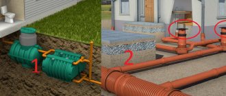
How to make wall foundation drainage, design of the project – Profiled timber
Everyone who owns a private house or cottage has personally encountered, or at least heard of, cases of basement flooding with groundwater and melt water.
Mold on the walls coming from the basement, food and things spoiled by moisture, gradual destruction of the foundation of a wooden house - the foundation, this is not the entire list of troubles that can happen to a house in the absence or improper installation of such an important engineering structure as wall drainage.
In an area with a high groundwater level, a depth of only one and a half to two meters will lead to the appearance of moisture in the basement of the building. And the best protection can only be provided by an integrated approach to solving the problem - waterproofing the basement and installing wall drainage of the building.
It is also impossible to do without installing a drainage system on the site in the case where the structure is located on an area with clay soil or loam, and in places where the soil is capillary moistened. According to the requirements of SNIP (building codes and regulations), drainage installation is carried out at the stage of forming a pit for pouring the foundation.
Basic principles of operation of the drainage system
Precipitation and spring melting of snow often lead to excessive moisture in the top layer of soil in a personal plot. Under normal conditions, evaporating from the surface of the earth and seeping into the lower layers of the soil, moisture disappears, taking part in the endless cycle of the water cycle in nature.
However, with a certain soil structure, it is possible for natural waters to hide and, as a result, swamping of the area, up to the formation of small lakes and ponds. Most often, this picture can be observed in areas with clay soil or containing a large amount of loam.
The water-impermeable layer is located at a depth of fifty centimeters to several meters, retaining enormous masses of water and making it impossible to carry out any construction work without first draining the site.
A drainage system is a complex of engineering and technical construction structures, the main purpose of which is to protect buildings and structures from the harmful effects of moisture, erected in areas and areas prone to waterlogging.
Groundwater and meltwater, having reached the clay layer, no longer stagnate, but are collected and removed from the site by a complex and carefully calculated system of traps, water conduits, storage and pumping wells.
The most reliable and effective system for protecting a house built on a site with clay soil is wall drainage. The simple design and relatively low financial costs required to install this type of protection contribute to its popularity and widespread use.
Structurally, it consists of drainage pipes laid around the perimeter of the entire building - drains that are used to drain water. They are located at a depth of thirty to fifty centimeters below the level of the foundation cushion.
Inspection wells are installed at the corners of the building, at the junctions of pipes. The system of pipes and wells is closed to the last pumping well, located in the lowest place of the site.
From it, water flows into a storm drain or natural reservoir.
In the case where the outlet point is located above the level of the pumping well, it is necessary to install additional pumping equipment responsible for pumping out water. In all other cases, water leaves the well by gravity.
Calculation of the wall drainage system of a building
Designing a drainage system requires compliance with certain conditions, on which its efficiency and performance directly depend. Drains should be located with a slight slope, two centimeters per meter of length, towards the pumping well or collecting manifold.
Inspection wells are located no further than forty meters from each other on straight sections, and twenty meters from the place where the pipes turn around the corner of the house. The depth of the elements responsible for drainage must be greater than the depth of soil freezing in a given climatic zone.
The drainage system of the foundation slab should be three or more meters away from the house.
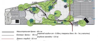
As an example, you can solve a simple problem. The length of the house is twenty meters and the width is ten. The distance from the house to the pumping well is fifteen meters. At what minimum possible slope will the system be operational?
The length of the system’s drainage pipes will be forty-five meters (ten plus twenty and plus fifteen meters from the corner of the house to the pumping well). The minimum possible slope will be ninety centimeters (two centimeters per meter of drainage pipe length). A typical wall drainage project usually contains a similar calculation.
But the installation of wall foundation drainage is not limited to calculating the required slope. The design of such a system also takes into account the diameter of the pipes - drains, filter materials, the nature and quality of the soil, and the overall throughput of the system.
Structural elements and materials for the construction of a drainage system
The development of modern technologies significantly simplifies many types of construction work, in particular, the installation of wall drainage of the foundation. The use of plastics and polymers, artificial insulation and synthetic filter fabrics turns what was once a complex and time-consuming task into a one-day job.
Drainage pipes made of polyvinyl chloride, low-density polyethylene or polypropylene are used as water conduits. Unlike earlier plastic pipes, polymer structural elements are flexible, ductile and much less fragile.
The drainage pipe is a polymer structural element with two perforation zones located opposite each other. The total area of the holes ranges from one-half to one percent of the pipe surface area.
Drains are available with filters made of geotextile fabric or coconut fiber to protect the perforated holes from clogging with soil particles, or without filters at all.
In the latter case, before laying in the ground, the pipes should be wrapped in several layers of geotextile.
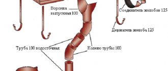
The connection of the water pipeline elements to each other, their coupling with inspection and pumping wells, is carried out using elbows and couplings made of polymer material. The main advantages of this type of structural elements are their low price, low weight, ease of installation and durability.
As additional wall drainage, the project often involves the use of profiled polymer membranes.
PPM is a polyethylene film equipped with protrusions formed by hot pressing. The height of the protrusions can vary from eight to twenty millimeters.
Two-layer membranes are equipped with a layer of geotextile fabric, and three-layer membranes additionally include a smooth polyethylene film.
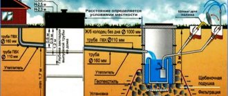
This is approximately what wall drainage looks like in cross-section
The membrane is installed on the waterproofed surface of the house foundation, with a layer of geotextile fabric to the ground. By filtering water from the soil and directing it into the pipes of the drainage system, the PPM layer increases the efficiency of the drainage system, while simultaneously increasing the level of waterproofing of the building foundation.
Artificial insulation serves to prevent freezing of the soil at the site where drainage pipes are laid, thereby protecting the system from breakdowns and ruptures due to the formation of ice plugs.
Also, the installation of wall foundation drainage requires the use of natural materials such as sand, gravel and small crushed stone. Of these, at the final stage of work, the main filter layer is formed, directing water from the surface to the drainage pipe system.
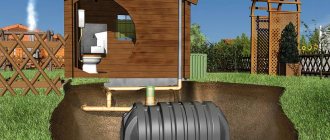
DIY drainage system
If, contrary to the requirements of SNIP, a drainage system was not included in the design of the house, and during the construction of the building no one noticed this serious miscalculation, there is an opportunity to correct the situation.
On the Internet you can easily find a project for wall drainage of the foundation. Photos and video materials will help you see the stage-by-stage drainage installation performed by experienced builders.
And people for whom designing such systems is a job, not a hobby, will be happy to talk about all the possible difficulties and nuances.
The installation of wall drainage begins with preparing a place for laying drainage pipes - drains. At this stage, it is very important to maintain the slope necessary for the effective functioning of the system.
Using a laser level, it is necessary to measure the area and mark the places of height difference with poles. Using the stakes as a guide, you should arrange the bed with the calculated slope, adding sand if necessary.
As a result, you should get a sandy bed for laying drains, located at the desired angle to the collector or pumping well.
If drainage pipes with industrially installed filters made of geotextile or coconut fiber are used, installation can be carried out directly on the sand bed.
When using drains without filters, a geotextile sheet is laid on the sand bed. It will act as a filter. A layer of fine gravel is laid on the canvas, the main purpose of which is to increase the filtering drainage surface. Next, the drainage pipe is laid, and the orientation of the perforated holes is very important.
They should be located on the right and left sides of the pipe. The non-perforated part should face the sand bed. A layer of gravel three to five centimeters thick is also poured on top of the laid drain.
The protruding edges of the panel are folded overlapping and secured using plastic tension tapes, nylon cord or thread made from any synthetic material. The fact is that plastic and synthetics are not susceptible to the destructive influence of moisture, unlike materials of organic origin.
The resulting roll is covered with sand, which is one of the best soil options for backfilling. In addition, the filtering properties of the sand bed significantly increase the efficiency of the drainage system as a whole.
One of the important conditions for the long and trouble-free operation of the drainage system is good perforation of the perforated holes in the drainage pipes. To comply with this condition, it is necessary to pay special attention to the tightness of the geotextile wrapping of the pipes and the reliability of the fixation.
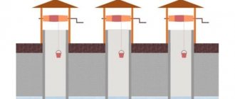
At the junctions of drainage pipes, in the corners of the building, inspection wells are installed, which are also prefabricated wells. Their main purpose is visual inspection and, if necessary, cleaning of the drainage system.
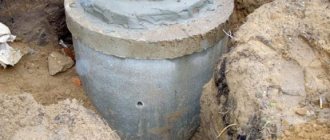
You can build an inspection well yourself by making a concrete casting, use large-diameter plastic pipes, or use factory-made plastic wells. The simplest and cheapest option is plastic pipes. The most functional are factory-made hatches and wells.
If the water drainage point is located above the level of the pumping well, it becomes necessary to use additional pumping equipment.
When installing wall drainage for the foundation, it is important not to forget to lay a layer of insulating material and make a concrete blind area at least fifty centimeters wide from the wall of the house.
The wall drainage is ready. Step-by-step photos will help you understand each stage of the work performed and will make it much easier to understand the process as a whole.
You can protect buildings and plantings from excess moisture by following the rules for drainage.
If the drainage system is considered closed, then it involves creating a trench in the ground, the depth of which is 70-150 cm and the width is 25-40 cm. It is extremely important to provide in advance a slope directed towards a natural or artificial water intake.
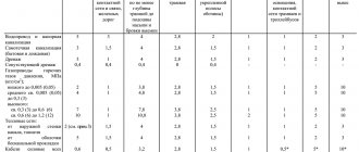
The slope based on which the drainage system is installed is described by SNiP as follows:
- - slope value 2 cm per 1 linear m, - on clay soil
- - 3 cm per 1 linear m, - on sandy soil.
Option for a drainage system with a slope angle of 2 cm per 1 m (i=0.02):
The bottom of the resulting depression is covered with a dense layer of crushed stone. Drains are laid on it, then everything is covered again with crushed stone. After this, the system is backfilled with soil.
Wastewater flows through drainage pipes, collects in a collector and ultimately flows into a water intake (river, pond, etc.).
Control of work on the drainage system occurs through special inspection wells, which are built from polymer or reinforced concrete rings.
IMPORTANT:
When the drainage system is initially installed correctly, the groundwater level does not rise above the permissible point, but, on the contrary, begins to decline. Thanks to this, the soil fertility in the area increases noticeably. If the drainage system is not built or errors were made in its installation, the negative impact on the soil as a whole cannot be avoided.
What should be in the project
Before starting any construction, it is necessary to develop a drawing. According to the requirements of SNiP, the foundation drainage project must include:
- Scheme of wells, location of drains (pipes), insulation;
Installation of a septic tank in accordance with the requirements of snip - Geometric data on the drainage system: ditch slope, trench dimensions, distances between prefabricated parts of the system;
- The diameter of the pipe used, the dimensions of the wells;
- Mounting materials used.
An example drawing of a drainage system made of concrete slabs
The resulting diagram will help to calculate the materials used, develop an estimate and approve the project in certain government agencies. In addition, according to SNiP, wall drainage of the foundation also takes into account the general slope of the site, the amount of average annual precipitation, the level of freezing of the earth and groundwater.
Basement drainage drawing
The next step is to install drainage according to the diagram . Regardless of whether a closed or open drainage system is used, the following operations must be performed before installing the drain:
- Clear the area of land where the drainage will be located. It is necessary to remove construction debris and stones that can damage pipes, remove plantings with large roots and ensure that tree roots do not break through the trench;
- The minimum depth of the trench is the maximum depth of soil freezing. Ideally, you need to make a ditch so deep that its bottom is slightly below the freezing level. If you ignore this rule, then in the cold season the drain will freeze and will not have time to thaw in the spring. Subsequently, the functionality of the drainage systems will be impaired;
- The walls of the deep drain must be strengthened and insulated. Sometimes craftsmen use geotextiles to insulate pipes directly, but in the northern regions it is much more convenient to install insulation in a ditch;
- A closed-type drainage system must combine several types of crushed stone of different fraction sizes. To backfill the lower level, a stone of large diameter is used, its size gradually decreases as it approaches the surface of the earth;
- The pipe is laid only on a sand cushion; this is necessary to form a kind of filter at the bottom of the ditch that does not allow water to pass through;
- Underground drainage can be a complex system consisting of numerous drains and highways or a simpler, perimeter one. The first is used on large swampy areas of land, while the second is necessary to drain the foundation and is placed around the house;
Wall drainage diagram - The permissible level of drainage depends on the groundwater level. But you need to take into account that the drainage ditch should be located at the lowest point of the site;
- In this case, the drainage well or septic tank is located even lower than the ditch, at an angle of at least 20 degrees;
- If you are installing a wastewater drainage system on the surface, then you must have an air conditioner. It is most often a metal mesh that filters rain or melt water from leaves and other debris;
- After completing all construction work, it is necessary to fill the trench for safety reasons. If external drains are used, and an open canvas should remain on the surface, then walkways or other floors must be installed. For a drainage system with a depth of 1 meter or more, soil backfill is used. To do this, the earth is sifted and heaped onto the ditch;
- SNiP allows the installation of drainage around the house at a distance of 1.5–2 meters from the outer wall of the building.