> Correct installation and proper clamping of tools on metal cutting machines are of paramount importance for defect-free operation. The tool must be secured so that during the cutting process its position relative to other elements of the tool is not disturbed.
The quality of the surfaces of the mounting bases is especially important for the correct orientation of the tool. If, for example, there are nicks in the tapered hole of the machine spindle or on the shank of the boring bar, errors are inevitable.
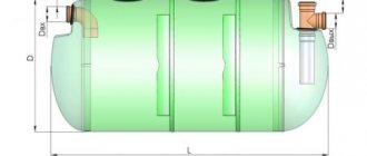
Rice. 30. Scheme of changing cutting angles depending on the installation of the cutter
When working on lathes, the correct installation of the cutter relative to the center line of the machine is very important, since the cutting angles and operating conditions of the tool depend on this.
When installing the tip of the cutter at the level of the centers, its rear angle α, front angle γ and cutting angle δ are located as shown in Fig. 30, b.
If you raise the top of the cutter above the axis of the centers (Fig. 30, a), then the rake angle γ will increase, and the cutting angle δ will decrease. This improves cutting conditions and facilitates chip flow along the front surface. However, it should be taken into account that an excessive decrease in the clearance angle α can lead to increased friction between the flank surface of the cutter and the workpiece and, as a result, to increased heating of the tool.
When installing the cutter below the center line (Fig. 30, c), the cutting conditions worsen, so the rake angle γ will decrease, and the cutting angle δ will increase, which complicates the process of chip separation.
Taking into account the dependence of the operating conditions of the tool on its position relative to the center axis of the machine, it is recommended that when rough turning parts made of medium-hard metal, install the cutter above the center axis or at its level, but not lower. When working with a carbide tool, it is advisable to set the tip of the cutter during rough turning - above the center axis by 0.01 of the diameter of the workpiece; during finishing turning - at the level of the center axis, or slightly below it.
To orient the cutter during its installation on the lathe, use the sharp end of the rear center or a special mark on the tailstock quill.
Improvements in tool mounting and clamping techniques are widely used by manufacturing innovators to ensure high quality work. For example, innovator turner V.G. Moiseev developed and successfully implemented a number of original devices that not only reduce processing time, but are largely aimed at improving its quality.
This is evidenced by the “Dream” milling chuck he proposed, which ensures strict centering of the cutting tool. Its “Soviet” boring head is also characterized by increased rigidity and accuracy. The same applies to the quick-change boring bar “Russia” and the boring head “Nadezhda”, developed by the innovator worker.
Of all the technological operations performed on metal workpieces, processing on turning equipment is the most common. That is why sharpening cutters for metal work is a very important process that should be performed correctly. The features of such a procedure depend both on the material to be processed and on the type of cutting tool itself (shaped, continuous, thread-cutting, boring, etc.).
Pereosnastka.ru
- Installation of cutters in the tool holder and workpieces in the chuck
- K
category: - Turning
Installation of cutters in the tool holder and workpieces in the chuck
Installation of the cutter. Before you start working on the machine, you need to install the cutter in the tool holder in the center and secure the workpiece (part) in the chuck.
There are fixed and rotating centers. They serve as a support for the long workpiece being turned. The centers are secured in the tailstock quill.
Having established the center in the quill, by rotating the handwheel, bring the apron with the caliper close to the tailstock. Then the cutter is secured in the tool holder using screws. The head of the cutter should protrude from the tool holder no more than 1.5 times the height of the rod, and the top of the cutting edges of the cutter should coincide with the tip of the center.
If the tip of the cutter is below the center tip, then one, two or three pads, selected in thickness, are placed under the rod. The shims are made of sheet steel; their width and length must correspond to the size of the cutter rod.
By selecting shims of appropriate thickness, the tip of the center coincides with the top of the cutting edges of the cutter. Then, using a key, secure the cutter with screws, and the tool holder with a handle.
The rules for installing all cutters are the same.
Installation of the workpiece in the chuck. The workpieces to be turned are secured to the machine spindle using various devices. The most convenient is a three-jaw chuck. It is designed very simply: in a housing with square holes for the key there are three movable cams.
The workpieces are secured in the chuck as follows. By rotating the key inserted into the square holes of the chuck, the cams are moved apart. Then place the workpiece between them and turn the key to bring the cams together; they must clamp the part firmly. The length of the part of the workpiece protruding from the chuck should not exceed three of its diameters.
Rice. 1. Centers: a - motionless; b - rotating
Rice. 2. Installation of the cutter (given conditionally)
Rice. 3. Three-jaw chuck
Remember!
The workpiece must be secured with a key from the side of each cam; to do this, the chuck is turned 1-2 turns.
Tool structure. A caliper is a universal measuring tool.
Rice. 4. Caliper ShTs-1 with a reading accuracy of 0.1 mm
It can be used to measure the thickness of parts, the width and depth of holes.
There are millimeter divisions on the tool's ruler bar. Together with the ruler, two fixed jaws are made: one for measuring external, that is, external, dimensions; the other is internal dimensions. The rod is fitted with a frame with movable jaws and a depth gauge, which is a thin, narrow ruler. The depth gauge is placed in the longitudinal groove on the back side of the ruler.
The frame can be freely moved along the rod and secured in the desired position with a screw. On the bevel of the lower part of the frame there are divisions (scale). This additional measuring device is called a vernier (Fig. 129). Vernier allows you to more accurately determine the dimensions of parts down to a tenth of a millimeter.
You all know that one centimeter is equal to ten millimeters. But we can say and write differently: a millimeter is one tenth, or simply a tenth, of a centimeter, that is, 1 mm = 1/10 cm = 0.1 cm. If you divide a millimeter into 10 parts, then each part is called one tenth of a millimeter and written as follows: 0.1 mm.
The length of the vernier is 19 mm, and the scale is divided into 10 equal parts. Thus, each division of the vernier is equal to 1.9 mm, i.e. 0.1 mm less than two millimeter divisions of the rod.
When the caliper jaws are closed, the zero division (initial) and the last division of the vernier coincide, respectively, with the zero and nineteenth divisions of the rod (less than 1 mm from mark 2). The remaining divisions of the vernier and the rod should not coincide.
Rice. 5. Vernier caliper
Rice. 6. Taking measurements with a caliper (a) and counting using a vernier (b)
Measuring with a caliper. Read the readings of the caliper, that is, determine the dimensions of the part as follows.
Whole millimeters are counted by divisions of the rod to the zero mark of the vernier. In our example, the zero division of the vernier is between the whole values (42 mm and 43 mm) of the scale. The number of whole millimeters on the rod in our example is 42.
Then it is determined which division of the vernier coincides with the division of the rod. The serial number of the matching vernier division shows the number of tenths of a millimeter—in our case, the fifth division.
So, the size of the part being measured is 42.5 mm.
Advertising:
Source: https://pereosnastka.ru/articles/ustanovka-reztsov-v-reztsederzhatele-i-zagotovok-v-patrone
Features of sharpening cutters for a lathe
There are certain nuances that should be taken into account when sharpening turning tools with your own hands using a sharpening machine. Thus, processing of the back surface of the cutter is carried out in three stages.
- Initially, the rear surface is machined at an angle equal to the rear angle of the holder itself. As a rule, it turns out to be slightly larger than the rear cutting angle (approximately 5 degrees).
- At the second stage, the back surface of the cutting plate itself is processed. In this case, it is sharpened at an angle exceeding the rear cutting angle by 2 degrees.
- The third stage is the formation of the required rear angle using finishing. It is important that such an angle is not formed on the entire rear surface of the cutter, but only on a narrow chamfer directly adjacent to the cutting edge.
The front surface of the turning tool is also sharpened in several stages. So, it is first sharpened to an angle equal to the angle of the cutting plate itself. This angle, as in the case of the flank surface, is slightly higher than the rake cutting angle. The actual cutting angle that needs to be formed on the front surface of the cutter is obtained by finishing sharpening or finishing. A narrow strip adjacent to the cutting edge of the carbide insert is subjected to these processes.
To make it more convenient to sharpen turning tools on sharpening machines, as well as to obtain angles with specified parameters, special pads are used, which are installed between the supporting surface of the tool and the machine table where it is located. To achieve even more accurate and high-quality sharpening, you can modify the design of the machine table with your own hands, making it adjustable in height and angle of rotation. After such modification of the machine, the need to use pads of a certain thickness disappears.
When sharpening a turning tool, it is important to ensure that its cutting edge is located at the same level as the center of the grinding wheel, but not lower than 3–5 mm in relation to it. The direction of rotation of the grinding wheel should also be taken into account. This is necessary in order to make the sharpening process safer, and also to minimize the risk of the cutting insert coming off the cutter holder. The sharpening wheel should rotate during sharpening so as to press the cutting plate, and not tear it away from the holder.
Laboratory work No. 7.
Purpose of work: Learn to correctly install and secure the cutter in the tool holder. Learn how to properly install and secure a workpiece. Master working with transverse and longitudinal feed dials. Learn to choose cutting mode.
Teaching aids: this development, posters “Basic turning operations”, “Turning cutter”.
Equipment" screw-cutting lathe TV-4 (TV-6).
Devices for fastening incisors.
Devices for securing workpieces.
Tools: straight cutter, bent cutter, caliper, chuck wrench, tool holder wrench.
Protective equipment: glasses, protective screen.
Materials: steel blanks D = 12 – 20 mm, length 80 – 120 mm.
Work progress: Using the poster, study the rules for securing the cutter in the tool holder. Come to the machine. Inspect the machine carefully. Make sure the machine is in good working order and has a ground connection. Manually check the operation of the movement mechanisms. Remove everything unnecessary from the machine. Place the box with the cutters on the nightstand. Turn on the machine. Make sure the mechanical feed mechanism and mechanical thread cutting are working. Before turning on the lead screw mechanism for thread cutting, disable the kinematic pair of the gear wheel and the rack by pulling out the rack engagement button.
Take a straight cutter. Install it so that the main cutting edge of the cutter is on top. The side wall of the cutter should rest on the side wall of the tool holder. Lightly secure the cutter with screws first. Take the back center. Extend the tailstock quill by 30 - 40 mm. With a sharp movement of your hand, insert the rear center into the tailstock quill. Bring the caliper to the tailstock. Loosen the tool holder screws. By placing pads under the sole of the cutter, ensure that the height of the tip of the center and the top of the cutter match. Installation of more than 3 pads is prohibited. The dimensions of the linings should not be larger than the dimensions of the sole of the cutter. The shims must not protrude beyond the tool holder. Toolholder overhang, i.e. the distance from the longitudinal axis of the outer fastening bolt to the top of the cutter should not be more than 1.5 times the height of the cutter. The longitudinal axis of the cutter must be perpendicular to the longitudinal axis of the workpiece. Secure the cutter by turning the cutter holder screws with a wrench.
Fig. 1. Setting the cutter overhang. Fig.2. Setting the cutter to the center height
tailstock
Workpieces are secured on a lathe depending on their length. If the length of the workpiece does not exceed 5 of its diameters, then the workpiece is attached and sharpened in the front center.
Fig 3. Turning a workpiece in the front center: a – setting the cutter to the cutting depth, b – top view of longitudinal turning. 1,2,3,4. stops that limit the movement of the cutter, and, consequently, the length of processing.
Rice. 4. Scheme of turning long workpieces: a – with fastening in a chuck with compression at the rear center; b – in the anterior and posterior centers.
Workpieces longer than 5 of their diameters cannot be sharpened only in the front center, because under the influence of the force of the cutter, it will be bent, and it will hit the objects surrounding it. To prevent bending of workpieces with a length of five to ten of their diameters, they are sharpened in the front center with the tailstock being pressed.
Fig.5. Turning a workpiece using a fixed steady rest, a – turning diagram; b – device of a fixed steady rest. 1 – steady rest body, 2 – locking screw, 3 – cam screws, 4 – cams, 5 – cover, 6 – nut (asterisk), 7 – nut, 8 – bar
If the workpiece has a length exceeding 10 of its diameters, then securing the workpiece at the front and rear centers does not ensure reliable installation. To turn long workpieces, it is necessary to install additional supports to prevent the workpiece from flying out of the centers. Such devices are called lunettes. They can be movable or immobile. Fixed rests are installed on the machine bed, and movable ones are installed on the longitudinal carriage of the support. The movable steady rest moves during the cutting process along with the support. The cams of the movable steady rest are constantly opposite the cutter. Thus, the cutter, exerting pressure on the workpiece, acts as a third cam.
As can be seen from the figure, before installing the steady rest, a neck is machined onto the workpiece along the diameter of the product. The cams of the steady rest cover the neck and fix the workpiece on the central axis of the machine. This is necessary to ensure that any section of the workpiece has the same diameter. If the axis of the workpiece deviates from the central axis of the machine during processing, the result will be a cone rather than a cylinder. The ends of the workpiece are fixed at the front and rear centers.
Rice. 6. Turning of a long workpiece using a movable rest. a – movable steady, b – processing scheme. I – steady rest body, 1 – cam movement screws, 2 – locking screws.
1. Select a workpiece with a diameter of 12 - 16 mm and a length of 80 - 100 mm.
2.Check the curvature of the workpiece on the correct plate. If it is crooked, straighten it with a hammer on the correct slab. Make sure that the ends of the workpiece are not bent and there are no burrs on them. Curvatures at the ends of the workpiece lead to runout of the workpiece in the chuck
Fig.7. The sequence of installing the workpiece in the lathe chuck
3. Turn off the machine motor. Using a chuck wrench, loosen the jaws until the workpiece fits between them. Using the chuck wrench, turn the machine chuck so that one of the jaws is at the bottom. With your right hand, place the workpiece on the lower cam. Make sure that the workpiece rests on the lower cam by at least 50 mm. Rotating the chuck wrench, bring the jaws together so that they lightly grip the workpiece. Take a ruler or caliper with your right hand and measure the distance from the jaws to the end of the workpiece. This distance, called the departure of the workpiece from the chuck, should not be more than 5 of its diameters. After making sure that the overhang of the workpiece when turning in the front center does not exceed 5 of its diameters, finally secure the workpiece in the chuck. To do this, with small jerks of the chuck wrench, tighten all 3 conical wheels of the chuck in sequence. After securing the workpiece, put the key on the bedside table and turn on the machine engine. Look carefully at the rotation of the workpiece.
Make sure that when the chuck rotates, the workpiece rotates without runout. Workpiece runout is allowed no more than 0.5 mm. If the runout is greater than the specified tolerance, then stop the machine. Wait until the spindle comes to a complete stop and loosen the chuck jaws. Carefully inspect the workpiece. Determine the cause of the beating and eliminate it. Sometimes the workpiece breaks due to a shape error. This type of beating can sometimes be eliminated using the following technique. After the chuck has completely stopped, loosen the clamp of the chuck jaws and turn the workpiece in the jaws by one third of a turn. Secure the workpiece. Turn on the machine. If the workpiece still hits, then repeat the previous technique again. If this does not help, replace the workpiece or try installing it in the chuck with a different end. It is prohibited to correct the workpiece runout using hammer blows, because this leads to severe wear on the cams.
To turn long workpieces, centering holes are made at their ends, into which, when installed on the machine, there are front and rear cones that fix the workpiece on the axis of the machine.
To transfer rotation from the spindle to the workpiece, it is secured either in the front center chuck or in clamps.
After installing the cutter and workpiece, calculate the cutting mode. Set the required spindle speed. Remove the allowance from the workpiece by an amount of 0.5 mm, for which a) with the machine turned off, move the cutter with a transverse feed until it stops in the workpiece, but only for a light touch. Don't make much effort, because... you can bend the workpiece.
Fig.8. Fastening the workpiece in the clamp: a – fastening method; b – installation of the workpiece in the center.
Rice. 9. Installation of the workpiece in the front center.
Fig. 10. Securing the workpiece with the tailstock: a - pressing the workpiece with the rear center, b - securing the tailstock quill.
b) Set the movable dial ring to 0.
c) Move the cutter in the longitudinal direction from the workpiece by 10 - 15 mm.
d) Determine the amount of movement of the cutter across the workpiece to establish the required depth of cut. Use the dial to set the calculated cutting depth.
d) Measure the diameter of the workpiece with a caliper.
f) Put on your glasses or lower your face shield.
g) Turn on the machine;
h) Manually bring the cutter to the workpiece and remove chips to a length of 5 mm;
i) Move the cutter in the longitudinal direction and turn off the machine;
j) Wait until the machine chuck comes to a complete stop and measure the diameter of the machined surface with a caliper. If the diameter of the machined surface turns out to be different from the specified one, find out the cause of the error;
k) Repeat the steps, achieving the accuracy of the resulting diameter;
m) Having achieved the desired diameter of the machined surface, grind the workpiece to a length of 50 mm using a manual longitudinal feed of the cutter.
This method of processing a workpiece is called the test chip removal method.
Repeat all the above steps, installing a bent cutter through the passage.
Complete the laboratory work according to the sample.
Laboratory work No. 7.
Installation of turning tool and workpiece on a lathe.
Removing test chips. Mastering the work with transverse and longitudinal feed dials.
Purpose of the work: (describe).
Teaching materials: (describe).
Equipment (describe).
Tool (describe).
Ensuring safety precautions (describe).
Installation and fastening of the cutter. Handling cutters at work. 4.25 /5 (85.00%) 4 votes
Installation and fastening of the cutter.
The installation of cutters in the tool holder is carried out depending on the material being processed and the type of processing.
The cutter is installed:
Rice. 1. Installation of the cutter along the center axis
(turning of cast iron, bronze, brass).
Rice. 2. Installation of the cutter above the center axis
(when turning steel 1-2 mm higher).
Fig.3. Setting the cutter exactly along the center axis
(boring of all materials).
When installing cutters, you need to strive to ensure that their overhang from the tool holder is as small as possible, since with a large overhang of the cutter, vibration is inevitable, which is extremely detrimental to the operation of the cutter and leads to chipping of the plate.
The overhang of the cutter should be no greater than its height.
To install the cutter in the center, use one thick spacer rather than several thin ones.
How to center a lathe cutter?
How to center a turning cutter using a square and a rod
If you are a beginner turner, you are probably wondering how to center the cutter. It often happens that you seem to have aligned the lathe cutter strictly in the center, but after a while it gets lost, which brings a lot of inconvenience.
Rules for sharpening turning tools
In order for the processing of workpieces on metal lathes to be effective, high-quality and accurate, the cutters should be regularly sharpened, thereby giving their working part the required shape and obtaining angles with the required parameters. Only tools whose cutting part is made in the form of a disposable carbide plate do not need sharpening. To perform such an important procedure in large manufacturing enterprises, machines with special devices are used, and a separate structural unit is engaged in this.
In order to sharpen a turning tool with your own hands on a home machine or do it in a small enterprise, you can use various techniques. This procedure can be performed using chemical reagents or using conventional grinding wheels. It should be noted that sharpening turning tools on specialized or universal machines that use an abrasive wheel is the most inexpensive but effective method of giving cutters the required geometric parameters.
Options for sharpening cutters with cutting inserts
Of course, the highest quality metal turning tools are sharpened on a machine specially designed for this procedure. If you don’t have such equipment at your disposal, you can use a universal machine with a grinding wheel. When choosing such a circle, it is important to pay attention to the material from which the working part of the tool being processed is made. So, in order to effectively sharpen a carbide cutter, you will need a carborundum wheel, which has a characteristic green color. Tools, the working part of which is made of carbon or high-speed steel, are perfectly processed on machines with medium-hard wheels made of corundum.
Sharpening of turning tools for metal can be done without cooling or with cooling, which is more preferable. If sharpening is carried out with cooling, then cold water should be supplied evenly to the place where the turning tool comes into contact with the grinding wheel. In the case when cooling is not used during the sharpening process, after sharpening it is impossible to immediately cool the tool sharply: this can lead to cracking of its cutting part.
You can learn how to sharpen turning cutters on a sharpening machine with your own hands using an instructional video. When performing this procedure, it is important to adhere to a certain sequence. First of all, the rear main surface is processed on the grinding wheel, then the rear auxiliary surface, and lastly the front surface is sharpened. The last stage of sharpening is processing the tip of the cutter - giving it the required radius of curvature.
During the sharpening process, the cutter is constantly moved in a circle, trying not to press it too hard (this can be seen in the video). It is necessary to adhere to this recommendation so that the surface of the circle wears evenly, and also so that the cutting edge of the turning tool is as smooth as possible.
How to properly install a cutter on a lathe?
Why is the correct installation of the cutter on a lathe necessary and how to carry out the installation correctly? Basic rules, as well as some subtleties.
The entire course of the turning process on lathes from the very beginning until the final result is mainly determined by the correct installation of the cutter in the tool holder. Otherwise, if it is positioned incorrectly, the machine faces fairly rapid wear of the cutting edge.
It is also not uncommon for this problem to cause serious equipment breakdowns, which often entail significant material losses in production.
Before starting, you must first thoroughly clean the supporting surfaces of the holder. The main rule for installing a cutter on a lathe is essentially that its top must be at the levels of the machine center line.
But in other cases, to further improve the performance of the cutter, minor deviations are allowed. For example, during the roughing process, the part is installed with a slight excess above the level of the centers, ranging from 0.3 to 1.2 mm (depending solely on the diameter of the workpiece).
A completely different case is finishing turning, in which the cutter is installed with a reduction by a similar amount.
The linings themselves also deserve special mention: they should be prepared as a whole set immediately in advance. There is no need to replace them with pieces of metal or other materials.
The shims must be placed on the supporting surface of the tool holder, while controlling the overhang of the tool - it should not exceed 1.5 times the height of the rod, otherwise vibration of the part cannot be avoided during operation of the machine.
Further adjustment of the cutter to the required depth can be done in two ways: using the test chip method or with a cross-feed dial. When choosing the first technology, the cutter is brought close to the first contact with the surface of the rotating part.
After which it is moved to the right and then the cutting depth is set to the eye. If the diameter of the part’s groove is then larger than required, everything is repeated with a new cutting depth until the required result is obtained.
- Video: adjusting (installing) cutters for a lathe.
Source: https://metmastanki.ru/ustanovka-reztsa-na-tokarnom-stanke
General rules for installing a cutter in a tool holder
Right and left cutters Read more: Cutting modes for rough turning with high-speed cutters
1.7 General rules for installing a cutter in a tool holder
To prevent the cutter from vibrating during operation, which can result in chipping of its cutting edge, the length of the overhanging part of the cutter, or, as they say, the overhang, should be as short as possible. In Fig. 6, a shows the correct one, and in Fig. 6, b - incorrect position of the cutter.
For the same purpose, shims for the cutter, used when installing the tip of the cutter relative to the line of the centers of the machine, should be positioned as shown in Fig. 6, c. The incorrect position of the pads is shown in Fig. 6, g. It is better to take one thick pad rather than several thin ones, since they are not always pressed tightly against one another (even when the tool holder bolts are tightened), which can also cause vibration of the tool.
The cutter must be installed at right angles to the part (Fig. 6, e). If you install the cutter according to Fig. 6, e, then during work under the pressure of the removed chips it can turn to the right and go deeper into the workpiece.
1.8 Some features of working with carbide cutters with negative rake angles
Working with cutters with negative rake angles makes it possible to increase cutting conditions, but causes an increased load on the machine mechanisms and the workpiece. Therefore, to ensure normal operation, the following basic rules must be observed.
Rice. 6 – Installation of the cutter in the tool holder: correct (a, c, e) and incorrect (b, d, f)
1. The machine on which the work is performed must be in perfect order. The bearings must be properly tightened; the transmission belt and the clutch available on the machine must fit well; The machine support should move smoothly, without jerking.
2. The part being processed both in the chuck and in the centers must be securely fastened.
3. When working at high speeds, the rear center of the part must be carbide or rotating.
4. When installing the cutter relative to the center of the machine during rough turning, its tip should be set above the center by 0.01 of the diameter of the workpiece.
5. To avoid vibrations of the cutter, its overhang should not exceed the height of the holder.
6. You should only work with a polished cutter.
7. The cutter should be brought to the part only when it is rotating. The cutter should be inserted into the part manually and gradually, so that the rear auxiliary surface does not touch the surface being processed. Only after the plunge is completed can the automatic feed of the caliper be turned on.
8. The cutter should be retracted before the machine stops, having first turned off the automatic feed.
9. When turning on the crust, you should work with the greatest permissible depth of cut and avoid sliding the cutter on the scale.
10. The width of the cut should not exceed 2/3 of the length of the cutting edge of the cutter.
1.9 Cutting modes for rough turning with carbide cutters
The depth of cut during rough turning is usually slightly less than the full machining allowance. The layer of metal that remains uncut forms an allowance for further processing. The feed is selected taking into account the cross section of the cutter, the depth of cut and the diameter of the workpiece. Feed values for the most frequently performed work on medium-sized machines are given in table. 6, 8, 10 and 12.
Table 6 - Feeds (in mm/rev) for rough turning of steel with carbide cutters
Table 7 - Cutting speeds (in m/min) for rough turning of carbon, chromium, chromium-nickel steels and cast steel with carbide cutters
Table 8 – Feeds (in mm/rev) during rough turning of steel with carbide cutters with an additional cutting edge (φ1 = 0)
Determining the cutting speed for this processing is carried out in two steps:
1) using one of the tables (Tables 7, 9, 11 or 13), the cutting speed is determined for the conditions closest to the specified ones;
2) the numerical value of this speed is multiplied by correction factors that take into account the specific conditions of the upcoming processing.
The most important of these conditions are the durability of the cutter (coefficient K1), the mechanical properties of the material being processed (coefficient K2), the condition of the processed surface (coefficient K3), the material of the cutter (coefficient K4) and its main angle in the plan (coefficient K5) - The values of these coefficients are given in table 14.
Table 9 – Cutting speed (in mm/rev) for rough turning of carbon, chromium, chromium-nickel steels and cast steel with carbide cutters with an additional cutting edge (φ1 = 0)
Table 10 — Feeds (in mm/rev) for rough turning of gray cast iron with carbide cutters
Table 11 – Cutting speeds (in m/min) for rough turning of gray cast iron with carbide cutters
Table 12 – Feeds (in mm/rev) for rough turning of gray cast iron with carbide cutters with an additional cutting edge (φ1 = 0)
Table 13 – Cutting speeds for rough turning of gray cast iron with carbide cutters with an additional cutting edge (φ1 = 0)
Table 14 – Correction factors to the table values of cutting speeds with carbide cutters
Right and left cutters Read more: Cutting modes for rough turning with high-speed cutters
Information about the work “Finishing processing of external and internal cylindrical surfaces”
Section: Industry, production Number of characters with spaces: 57684 Number of tables: 0 Number of images: 45
Similar works
Drawing up a process for implementing machining of a “Planck” part
44285
6
2
... obtaining a workpiece for each method by comparing them by cost. The cost of production of workpieces, without taking into account the costs of preliminary mechanical processing, is determined by the relationship [1, p. 61]: (7), where Gd is the mass of the part, kg Gzag is the mass of the workpiece, kg Who is a coefficient that takes into account additional payments for heat treatment and cleaning billets, rub/t Ktch – coefficient, ...
Volume stamping and metal cutting
89155
4
30
… ;в=6 kg/mm2 – the tensile strength of the deformable material at the temperature of the end of stamping. Mm = 1781.9 kg = 1.8 t. In accordance with the calculation, for stamping a gear blank according to OST 2KP12 - 1 - 87, we select a steam-air hammer with a mass of falling parts of 2 tons. 2. Metal cutting 2.1 Introduction Metal cutting – technological processes of metal processing by ...
Technological process of assembling the die matrix of cold die forging of the VAZ 2108 internal hinge body
131357
33
22
... location, equipment and technological operations performed The processing of the “bottom insert” part is carried out at the production site for the production of dies for cold die forging. Table 3.1.1 Description of the technological process and equipment of the production site N op Name of operation Name of equipment Work performed on this equipment 05 ...
Blade tools
25141
0
6
... ; 2) variability in the thickness of the cut layer and the working length of the blade. In practice, the following are used: peripheral and end milling - milling with a peripheral and end blade tool, respectively (see Fig. 2.5, a, b); circular milling - milling a surface of rotation (see Fig. 2.5, c); Female milling - milling with a tool whose teeth are located on the inside...
Installation of cutters relative to the line of machine centers
The operating conditions of the cutter vary depending on the position of its tip relative to the line of machine centers.
In Fig. 5, b, the cutter is installed in such a way that its top is at the height of the centers of the machine. In this case, its rear angle is a, the front angle is y, and the cutting angle is b.
When installing the same cutter above the center line (Fig. 5, a), the rake angle y increases, and the cutting angle b decreases. The cutting conditions are easier, since chips flow more easily along the rake surface than with a smaller rake angle and, therefore, a larger cutting angle.
At the same time, however, the clearance angle a decreases, which is permissible only to certain limits in order to avoid strong friction of the rear surface of the cutter against the machined surface (cutting surface). If the same cutter is installed below the machine center line (Fig.
5, c), then, on the contrary, the rake angle y decreases, and the cutting angle b increases. As a result, the cutting conditions are significantly worse compared to the first two cases. Increasing the clearance angle a, resulting from installing the cutter below the center, does not improve the chip separation process.