HomeOur productsSurface runoff treatment facilitiesStorm treatment facilities (VOC)
Storm sewer treatment facilities are designed to treat surface, industrial wastewater and storm drains. According to the standards of the water legislation of the Russian Federation, before discharging storm and melt wastewater into reservoirs, city or storm sewers, it is necessary to carry out a number of measures to bring the quality of purified water to the required indicators (VAT in accordance with the technical conditions for the discharge of stormwater). Depending on the nature of the wastewater discharged: city, rain or industrial sewerage, different requirements are imposed on the quality of stormwater treatment. Pollution limits for surface runoff are suspended substances and petroleum products.
Types of local stormwater treatment facilities
There are two main types of local treatment facilities for rain and melt water: storage and flow types. Separately, we can distinguish biological ponds of the gabion type.
Cumulative type of local treatment facilities
The main element of the storage type VOC is the storage tank, designed to collect and accumulate surface runoff. Excessive flow is discharged through the separation chamber of the storage tank. Then, using a sewage pumping station (SPS), the accumulated wastewater is uniformly supplied for treatment. Storage-type treatment facilities are designed to receive the bulk of precipitation of any intensity, which is maximally concentrated in terms of contaminants, and uniformly purify the accumulated runoff within 72 hours.
Flow type wastewater treatment facilities
Flow-type structures are selected for water flow calculated using the maximum intensity method at the design site of the storm drain collector, taking into account the time of surface concentration and the time it takes for the runoff to travel through pipes and trays. Thus, flow-type VOCs have become widespread for draining runoff from small catchment areas, such as garages, gas stations, shopping center parking lots, and highway drainages. Gabion-type structures are used mainly in road construction.
HOW TO SELECT THE CORRECT EQUIPMENT FOR STORM WATER CLEANING
In order for stormwater treatment systems to cope with surface flow, it is necessary to take into account a number of parameters that determine the capacity of the equipment and its location.
First, you need to determine the catchment area and the type of ground surface coverage (asphalt, or lawn, or a combined coating in a certain ratio). One type of coating simply distils, the other absorbs water. These coating properties influence the volumes entering the treatment plant.
Secondly, we take into account the intensity and possible peak volumes of wastewater characteristic of the climatic conditions at the installation site. To avoid breakdowns when the calculated flow rates are exceeded during the flood or heavy rain season, a bypass pipeline is installed that prevents flooding of the treatment systems. In this case, the wastewater is discharged into the reservoir without treatment. Considering that the volume of water has increased significantly, the concentration of substances dissolved in the flow tends to the standard discharge values. The second option for maintaining the functionality of equipment during a flood is to install an averaging tank of a larger volume; experts also call it an “averaging tank.” It must absorb all excess and gradually give it away for purification. This is done when it is impossible to allow sewage to be discharged, for example, into a protected lake.
Thirdly, to ensure the gravity flow of the process, it is necessary to provide for the features of the local landscape - uplands and lowlands.
Modular wastewater treatment plants HELYX™
TM.HELYX produces a wide range of modular equipment for the construction of stormwater treatment facilities. The products are made of composite materials, have a long service life and are suitable for organizing any type of local treatment facilities.
The range of manufactured equipment includes capacitive blocks of both individual purification stages and several stages grouped into a single block, for example, a sand trap-gasoline-oil separator, an oil trap-sorption filter. Even complex stormwater treatment plants in a single building. For treatment plants of any type, if it is necessary to discharge purified water into a reservoir, it is necessary to install a HELYX UFO unit to disinfect wastewater. Similarly, HELYX orbital filters are used to achieve the standards. Vortex separators, storage tanks, sand traps are used both as part of a chain of flow-through treatment facilities and as separate stages of other types of treatment facilities, including industrial wastewater, as well as for organizing circulating water supply systems.
Storm drainage system
The practice of operating storm sewer treatment facilities shows that it is most advisable to use them with a comprehensive storm water treatment system, which includes components such as a sand catcher, an oil catcher, and a sorption filter. A system in this composition allows it to be used with maximum efficiency, ensuring a high degree of purification of rainwater throughout the entire operation. The mode of movement of surface wastewater in treatment facilities is non-pressure. This technological solution allows:
Avoid the use of pumping equipment and energy costs; Achieve high reliability due to energy independence, simplicity and ease of operation; Avoid additional costs since constant staff presence is not required. The distribution well performs distribution functions by supplying a calculated amount of wastewater to storm sewer treatment systems, and in the case of intense flow, which occurs, for example, during heavy rain, relatively clean water flows to the bypass line (bypass), and dirty water is sent directly to the system storm sewer. The use of this design can significantly reduce the cost of storm sewerage, the price of which is significantly lower than standard wastewater treatment equipment.
A sand trap is a container in which sedimentation of insoluble particles contained in water occurs, the density of which does not exceed 1500 kg/m3. Installed when there is a high content of suspended solids in wastewater. The purpose of the installation is to prevent suspended substances from entering the oil catcher and gravity sorption filter, thereby increasing their service life without sorbent regeneration. The principle of operation of the sand trap is based on the method of gravity, with the help of which particles that are heavier than wastewater settle to the bottom of the sand trap. Having collected at the bottom of the sand trap, various particles and impurities require removal using a special sewer truck. Pumping is carried out through a technical well for maintenance.
Technical characteristics of the Sand Trapper KTR PO
| Consumption, l/s | 10 | 15 | 20 | 25 | 30 | 40 | 50 | 60 | 70 | 80 | 90 | 100 | |
| Diameter, mm | DN | 1600 | 2000 | 2000 | 2000 | 2400 | 2400 | 2400 | 3000 | 3000 | 3000 | 3200 | 3200 |
| Length, mm | L | 5000 | 4500 | 6200 | 7600 | 6100 | 7800 | 9700 | 8500 | 10000 | 11300 | 9000 | 9900 |
| Entrance height. pipes, mm | hin | 1400 | 1600 | 1800 | 1750 | 2000 | 2000 | 2000 | 2600 | 2600 | 2600 | 2600 | 2600 |
| Output height pipes, mm | hout | 1350 | 1550 | 1750 | 1700 | 1900 | 1950 | 1950 | 2550 | 2550 | 2550 | 2550 | 2550 |
| Pipe inlet/outlet diameter, mm | D | 160 | 200 | 200 | 250 | 250 | 315 | 315 | 315 | 315 | 400 | 400 | 400 |
The oil separator performs the functions of purifying surface wastewater mechanically in order to remove the impurities contained in it, which include waste products of oil and oils, as well as fuel combustion products. Wastewater flows by gravity into the device, where it undergoes several stages of purification. The device operates using coalescence technology. The latter ensures fusion in liquid waste upon contact of isolated droplets of petroleum products. This process is activated through the use of specially designed coalescent filters. Passing through them, small particles are delayed and collide with each other, merging into a single whole. In this case, the particles of petroleum products become much larger and rise to the surface. Thus, the main composition of petroleum products is located at the top, from where it is pumped out through a technical well using a special sewage disposal machine.
Technical characteristics of the KTR BMO gasoline oil trap
| Consumption, l/s | 10 | 15 | 20 | 25 | 30 | 40 | 50 | 60 | 70 | 80 | 90 | 100 | |
| Diameter, mm | DN | 1600 | 1600 | 2000 | 2000 | 2000 | 2000 | 2500 | 2500 | 2500 | 3200 | 3200 | 3200 |
| Length, mm | L | 2700 | 3500 | 3300 | 4000 | 4600 | 6000 | 5500 | 6000 | 6500 | 5300 | 5900 | 6400 |
| Entrance height. pipes, mm | hin | 1390 | 1350 | 1750 | 1700 | 1700 | 1635 | 2135 | 2135 | 2135 | 2750 | 2750 | 2750 |
| Output height pipes, mm | hout | 1320 | 1280 | 1680 | 1630 | 1630 | 1565 | 2065 | 2065 | 2065 | 2680 | 2680 | 2680 |
| Pipe inlet/outlet diameter, mm | D | 160 | 200 | 200 | 250 | 250 | 315 | 315 | 315 | 315 | 400 | 400 | 400 |
The sorption filter is a cylindrical fiberglass container with pipes for inlet and outlet of water, the purpose of which is to ensure post-treatment of wastewater during the entire period of operation of stormwater treatment facilities. This filter uses dynamic adsorption, i.e. a process in which an adsorbent solution flows through a fixed bed of sorbent. Natural shungite stone, activated carbon and hydrophobic NES sorbent are used as sorbents, which allows the operation of treatment facilities without replacing the sorption load for more than 3 years; ensure a high degree of cleaning throughout the entire period of operation. The boundary between used and fresh sorbent is not clear. The service life of the sorbent is determined by the degree of purification at the outlet and depends on the level of contamination by suspended substances, as well as on the concentration of petroleum products at the inlet. After the sorption filter, the degree of purification can be up to 3 mg/l for suspended substances, and up to 0.05 mg/l for oil products. Systems without a sorption filter are used to treat surface wastewater up to the standards for discharge into the city sewerage system.
Technical characteristics of the KTR SF sorption filter
| Consumption, l/s | 10 | 15 | 20 | 25 | 30 | 40 | 50 | 60 | 70 | 80 | 90 | 100 | |
| Diameter, mm | DN | 1600 | 1600 | 1800 | 1800 | 1800 | 2000 | 2000 | 2400 | 2400 | 2400 | 2500 | 2500 |
| Length, mm | L | 2800 | 3800 | 4100 | 4900 | 5800 | 6200 | 7700 | 6500 | 8700 | 9600 | 9200 | 10400 |
| Entrance height. pipes, mm | hin | 1390 | 1350 | 1550 | 1500 | 1500 | 1635 | 1635 | 2150 | 2150 | 2150 | 2050 | 2050 |
| Output height pipes, mm | hout | 1320 | 1280 | 1480 | 1430 | 1430 | 1565 | 1565 | 2070 | 2070 | 2070 | 1980 | 1980 |
| Pipe inlet/outlet diameter, mm | D | 160 | 200 | 200 | 250 | 250 | 315 | 315 | 315 | 315 | 400 | 400 | 400 |
The control well serves for the convenience of taking samples for the quality of purified water. A disc valve is installed in the well, which, if necessary, shuts off the discharge of treated wastewater.
Surface wastewater treatment system KTR SBSF without sorption filter
The KTR SBSF system without a sorption filter is used to purify surface wastewater up to the standards for discharge into the city sewerage system. The system consists of two stages: a sand separator and an oil separator.
A sand trap is a container in which sedimentation of insoluble particles contained in water occurs, the density of which does not exceed 1500 kg/m3. Installed when there is a high content of suspended solids in wastewater. The purpose of the installation is to prevent suspended substances from entering the oil catcher and gravity sorption filter, thereby increasing their service life without sorbent regeneration. The principle of operation of the sand trap is based on the method of gravity, with the help of which particles that are heavier than wastewater settle to the bottom of the sand trap. Having collected at the bottom of the sand trap, various particles and impurities require removal using a special sewer truck. Pumping is carried out through a technical well for maintenance.
The oil separator performs the functions of purifying surface wastewater mechanically in order to remove the impurities contained in it, which include waste products of oil and oils, as well as fuel combustion products. Wastewater flows by gravity into the device, where it undergoes several stages of purification. The device operates using coalescence technology. The latter ensures fusion in liquid waste upon contact of isolated droplets of petroleum products. This process is activated through the use of specially designed coalescent filters. Passing through them, small particles are delayed and collide with each other, merging into a single whole. In this case, the particles of petroleum products become much larger and rise to the surface. Thus, the main composition of petroleum products is located at the top, from where it is pumped out through a technical well using a special sewage disposal machine.
Technical characteristics of the KTP SBSF system without a sorption filter
| Consumption, l/s | 3 | 6 | 8 | 10 | 15 | 20 | 30 | 40 | 50 | 60 | 70 | 80 | 90 | 100 | |
| Diameter, mm | DN | 1600 | 1600 | 1600 | 2000 | 2000 | 2400 | 2400 | 2400 | 2400 | 2400 | 3000 | 3000 | 3000 | 3000 |
| Length, mm | L | 2500 | 4500 | 5700 | 4700 | 8900 | 7300 | 8700 | 9200 | 10800 | 11300 | 8500 | 9600 | 10400 | 12100 |
| Entrance height. pipes, mm | hin | 1400 | 1400 | 1400 | 1800 | 1800 | 2100 | 2100 | 2000 | 2000 | 2000 | 2500 | 2500 | 2500 | 2500 |
| Output height pipes, mm | hout | 1300 | 1300 | 1300 | 1700 | 1700 | 2000 | 2000 | 1900 | 1900 | 1900 | 2400 | 2400 | 2400 | 2400 |
| Pipe inlet/outlet diameter, mm | D | 110 | 110 | 160 | 160 | 160 | 200 | 250 | 315 | 315 | 315 | 400 | 400 | 400 | 400 |
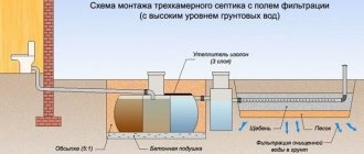
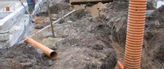
Installation of the KTR LOK system
Composition of Alta Rain and Alta Rain PRO modules
The Alta Rain storm drainage system consists of two main modules:
- Primary settling tank and coalescent filter module;
- Sorption filter.
The layout of Alta Rain modules is more complex, as it is designed to process larger volumes of runoff. Alta Rain PRO consists of:
- Receiving chamber block;
- Thin-layer sedimentation unit and coalescent filter;
- Sorption filter block.
Another feature of Alta Rain products is the unique design solution, thanks to which the main stage of purification is carried out on a coalescent filter and in a laminar settling tank. When using this technology, no additional consumables are required, therefore operating costs are significantly reduced.
The completely energy-independent mode of operation and the absence of any automation in the Alta Rain station eliminates the reduction in the efficiency of storm water treatment in the event of power outages, as well as the requirements for operating personnel.
Models of underground storm and melt water treatment systems
| Model | Productivity, l/s | Catchment area (approximate) / ha | Dimensions of blocks, m | ||
| Cleaning unit (LxWxH) | Sorption filter (LxWxH) | Pumping station (LxWxH) | |||
| PVO-SV-1.5 | 1,5 | 0,125 | 2.7x1x2.5 | — | 1x1x2.4 |
| PVO-SV-1.5U | 0.7x0.7x1.5 | ||||
| PVO-SV-1.5N | 3.4x1x2.5 | — | 1x1x3.35 | ||
| PVO-SV-1.5UN | 0.7x0.7x1.5 | ||||
| Air defense SV-2.5 | 2,5 | 0,25 | 2.7×1.6×2.5 | — | 1x1x2.4 |
| PVO-SV-2.5U | 0.7x1x1.5 | ||||
| PVO-SV-2.5N | 3.4×1.6×2.5 | — | 1x1x3.35 | ||
| PVO-SV-2.5UN | 0.7x1x1.5 | ||||
| PVO-SV-5 | 5 | 0,5 | 4×1.8×2.5 | — | 1×1.2×2,4 |
| PVO-SV-5U | 1.2×1.2×1.5 | ||||
| PVO-SV-5N | 4,7×1,8×2,5 | — | 1×1.2×2,4 | ||
| PVO-SV-5UN | 1×1,2×3,35 | ||||
| PVO-SV-10 | 10 | 1,0 | 2x(4x1.8x2.5) | — | 1.2×1.2×2,4 |
| PVO-SV-10U | 2x(1.2x1.2x1.5) | ||||
| PVO-SV-10N | 2x(4.7x1.8x2.5) | — | 1,2×1,2×3,35 | ||
| PVO-SV-10UN | 2x(1.2x1.2x1.5) | ||||
| PVO-SV-15 | 15 | 1,5 | 3x(4x1.8x2.5) | — | 1.2×1.5×2,4 |
| PVO-SV-15U | 3x(1.2×1.25×1.5) | ||||
| PVO-SV-15N | 3x(4.7x1.8x2.5) | — | 1,2×1,5×3,35 | ||
| PVO-SV-15UN | 3x(1.2×1.25×1.5) | ||||
| PVO-SV-20 | 20 | 2,0 | 4x(4x1.8x2.5) | — | 1.2×1.8×2,4 |
| PVO-SV-20U | 4x(1.2x1.2x1.5) | ||||
| PVO-SV-20N | 4x(4.7x1.8x2.5) | — | 1,2×1,8×3,35 | ||
| PVO-SV-20UN | 4x(1.2x1.2x1.5) | ||||
Designation of station models:
- U - with a carbon filter.
- N – with pumping station.
- UN – with a carbon filter and pumping station.
Methods for implementing VOCs from our company
A storm sewer system is a complex multi-component engineering installation that requires specialized and high-quality development by qualified engineers. Stormwater treatment plants, called VOCs, are a key component of storm drainage that a construction site cannot do without. By turning to StroyKontrakt-5 LLC as a supplier of such storm drains and VOCs, you will receive durable, high-quality equipment from a Russian manufacturer.
Our company has been developing, designing and direct installation since 2008. During this time, StroyKontrakt-5 successfully implemented design solutions for the installation of stormwater treatment facilities. The equipment is made using the latest technologies and is made from durable materials. VOCs are already in use, and can also be installed in the future, at the following enterprises:
- factories that manufacture products for various purposes (aircraft manufacturing, production of building mixtures, production of plastic pipes, etc.);
- ice sports complex;
- furniture factory and many other objects.
We value our reputation and the trust of our business partners, so we produce and supply only high-quality equipment. All materials and design elements of VOC meet customer requirements and standards established by the relevant authorities. Environmentally friendly and wear-resistant products are used.
Methods for placing an order and determining the cost of equipment
You can get advice or place an order for a stormwater treatment system from StroyKontrakt - 5 in several ways:
- fill out the application form on the company's website;
- call the contact number;
- send a letter by email.
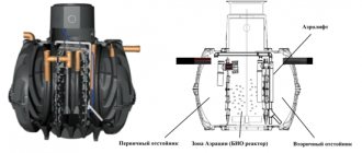
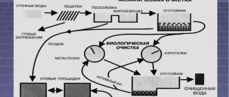
Design and principle of operation of storm sewer treatment facilities
The rainwater treatment system is a horizontal cylindrical tank, divided by internal partitions into compartments (chambers), in each chamber the water is purified from certain pollutants. A receiving and distribution well is installed in front of the treatment station.
- The first stage of cleaning is mechanical. For this purpose, sand separators are provided; they clean surface runoff from mechanical contaminants - sand, dirt, dust, leaves, and various debris. This cleaning step is carried out in the first chamber of the stormwater treatment plant;
- The second stage is wastewater treatment from petroleum products (fuels and lubricants, machine oils). Produced in an oil-gasoline separating chamber equipped with thin-layer coalescent modules;
- The third stage is post-treatment in the sorption compartment, here the final purification of surface wastewater from remaining oil products and suspended substances takes place; for this purpose, sorption filters with natural sorbent material are installed in the third chamber
- Sampling well - installed at the outlet of the station, and is used to take samples of purified water in order to determine the quality of purification
Technical characteristics of fiberglass storm water treatment plants
| Parameter name | OSLV 2 | OSLV 5 | OSLV 8 | OSLV 10 | OSLV 15 | OSLV 20 | OSLV 25 |
| Productivity, l/s (m³/hour) | 2 (7,2) | 5 (18) | 8 (28,8) | 10 (36 | 15 (54) | 20 (72) | 25 (90) |
| Overall dimensions of the station, no more (Ø/D), m | 1.5x6 | 1.9x7 | 1.9x9 | 2.4x9.1 | 2.4x12 | 3x12.8 | 3x14.7 |
| Station weight in transport position, t | 3 | 5 | 6 | 10 | 12 | 15 | 22 |
| Station weight at maximum filling, t | 18 | 31 | 40 | 62 | 72 | 110 | 144 |