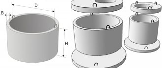
Dimensions length, width, height
The production of asbestos-cement profiles is organized in accordance with state standards: 3034095 for wave and 1812495 for flat.
Wave ACLs
Although the composition of the building material is the same, the size of the product may vary. This also applies to the thickness of the product. As a rule, it varies in the range from 5 to 9 mm. As for the width, it is determined by the number of waves.
The ACL profile depends on the cross-sectional shape and the distance between the waves. The cross-sectional shape is of two types - 40 by 150 and 54 by 200. The first number of this indicator (40 or 54) indicates the height of the wave, and the second (150 or 200), respectively, its pitch. The height of the slate is nothing more than the length of the segment connecting the top of the wave and the bottom, without taking into account the thickness of the profile.
| Slate option | Height | Width | Length | Wave step | |
| 7 waves. | 8 waves. | 6 waves. | |||
| 40/150/1750 | 40 | 980 | 1130 | 1750 | 150 |
| 54/200/1750 | 54 | 1125 | 1750 | 200 |
Note: Domestic manufacturers have the right to produce non-standard ACLs based on their own specifications.
Sheets with different profiles are classified into three groups:
- VO – regular profile;
- UV – unified;
- VU – reinforced.
- for ordinary ones - 1.2 by 0.68 m;
- for unified – 1.75 by 1.125 m;
- for reinforced ones, the slate length is 2.80 m.
- waves of modern asbestos cement sheets - six, seven and eight. For example, a standard 8-wave slate is 1.75x1.13 m with a thickness of 5.2 or 5.8 mm, area size is 1.977 sq. m. 7 and 8 have the same height, but the width is different, since the number of waves does not match.
Flat ACLs
Certain qualities of flat and wave profiles are similar, however, there are certain differences between them. For example, flat ones may not be pressed, which means that they will differ in their technical characteristics. It should be noted that flat ACLs are more durable compared to wave ones. For example, their compressive and bending strength reaches 90-130 and 20-50 MPa, respectively.
The main advantage of this material, most likely, is the variety of its uses. Just a few examples:
- the sufficiently low weight allows the use of flat profiles when constructing floors, and additional reinforcement elements are not used.
- quite often used as interior and exterior decoration of buildings;
- with their help, partitions of various types and vertical fences are erected.
- length can be 2.5, 3.0 and 3.5 m;
- width – 1.2 and 1.5 m;
- thickness – 0.6, 0.8 and 1.0 cm.
On the construction market you can also find industrially produced flat sheets of smaller dimensions (length - 0.6 m, width - 0.4 m), which are suitable for roofing.
It should be noted that manufacturers produce custom profiles of other dimensions and shades. The developed dyes are resistant not only to atmospheric influences, but also to fading.
2019stylekrov.ru
3.2. Applying dimensions
In the drawings of parts, dimensions are indicated based on the manufacturing technology of the part and the surfaces on which the part comes into contact with other parts of the assembly unit.
This affects the choice of design base.
Based is the process of giving the workpiece the required position relative to the selected coordinate system.
Read also: Bta212 600b connection diagram
A base is a surface or combination of surfaces, an axis or a point belonging to a product or workpiece and used for basing.
Design base - a base used to determine the position of a part or assembly unit in a product.
The basic rule for applying dimensions is to group dimensions related to one geometric element in one image, in the one in which this element is most clearly represented. It is not always possible to achieve this, but we always strive for this.
When indicating the size of an angle, the dimension line is drawn in the form of an arc with the center at its vertex, and the extension lines are drawn radially (Figure 3.2).
| Figure 3.1 | Figure 3.2 |
It is preferable to apply dimension lines outside the outline of the image. The use of contour lines, axial, center and extension lines as dimension lines is not allowed. The intersection of dimension and extension lines, shown in the crossed out Figure 3.3, a, is unacceptable. The correct dimensions for this case are shown in Figure 3.3, b.
| A | b |
As you can see, smaller dimensions should be placed closer to the contour of the part; the number of intersections of dimension and extension lines will be reduced, which will make the drawing easier to read.
The dimension line is drawn with a break if it is not possible to draw an extension line on one side of the image, for example, in the case of combining a view and a section (Figure 3.4, a), and also if the view or section of a symmetrical object is depicted only to the axis or with a break (Figure 3.4, b). The break of the dimension line is made further than the axis or break line of the object.
| A | b |
Dimension lines may be drawn with breaks in the following cases:
- when indicating the size of the circle diameter; in this case, the break of the dimension line is made further than the center of the circle (Figure 3.5);
- when drawing dimensions from a base not shown in this drawing (Figure 3.6).
| Figure 3.5 | Figure 3.6 |
The main line must be broken if it intersects with the arrow (Figure 3.5).
When depicting a product with a gap, the dimension line is not interrupted (Figure 3.7). The dimensional number must correspond to the full length of the part.
Figure 3.7
If it is not possible to place dimensional numbers and arrows between closely spaced solid main or thin lines, they are applied outside (Figure 3.8). Do the same when applying the radius size if the arrow does not fit between the curve and the center of the radius (Figure 3.9).
| Figure 3.8 | Figure 3.9 |
It is allowed to replace arrows with dots or serifs, applied at an angle of 45° to the dimension lines, if it is impossible to place an arrow between the extension lines (Figure 3.10).
Figure 3.10
Dimensional numbers must not be divided or crossed by any drawing lines. At the place where the dimension number is applied, the axial, center lines or hatch lines are interrupted (Figure 3.11).
Figure 3.11
Dimension numbers should be placed above the dimension line, as close to its middle as possible (Figure 3.12).
Figure 3.12
Dimensional numbers of linear dimensions with different slopes of dimension lines are placed as shown in Figure 3.13.
If it is necessary to apply dimensions to the shaded area, the corresponding dimensional number is applied on the shelf of the line - leader.
Figure 3.13 Angular dimensions are applied as shown in Figure 3.14.
Figure 3.14
In the area located above the horizontal center line, dimensional numbers are placed above the dimension lines on the side of their convexity, in the area located below the horizontal center line - on the concavity side of the dimension line.
Dimension numbers above parallel dimension lines should be placed in a checkerboard pattern (Figure 3.15).
Figure 3.15
When indicating the diameter size, in all cases the sign ? is placed before the size number. Before the dimensional number of the diameter (radius) of the sphere, the sign “O” is also applied? (R) without the inscription “Sphere” (Figure 3.16).
Figure 3.16 If it is difficult to distinguish a sphere from other surfaces in a drawing, it is allowed to write the word “Sphere” or the sign “O”, for example, “Sphere? 18, OR12." The diameter of the sphere sign is equal to the height of the dimensional numbers in the drawing. The dimensions of the square are applied as shown in the drawing (Figure 3.17). Figure 3.17
The height of the sign must be equal to the height of the dimensional numbers in the drawing.
When applying a radius size, place a capital letter R in front of the size number. With a larger radius, the center can be brought closer to the arc; in this case, the radius dimension line is shown with a bend at an angle of 90° (Figure 3.18). If it is not necessary to indicate the dimensions that determine the position of the center of the circular arc, then the radius dimension line may not be brought to the center and may be shifted relative to the center (Figure 3.19).
| Figure 3.18 | Figure 3.19 |
Rounding radii, the size of which on the drawing scale is 1 mm or less, are not shown in the drawing and their dimensions are indicated as shown in Figure 3.20. When applying the size of a circular arc, the dimension line is drawn concentrically to the arc, and the extension lines are parallel to the bisector of the angle, and the sign “” is placed above the dimension number (Figure 3.21).
| Figure 3.20 | Figure 3.21 |
The dimensions of the chamfers at an angle of 45° are applied as shown in Figure 3.22, a. It is allowed to chamfer at an angle of 45°, the size of which on the scale of the drawing is 1 mm or less, not to be depicted and its dimensions to be indicated on the shelf of the leader line, as shown in Figure 3.22, b.
The dimensions of chamfers with other angles are applied according to the general rules - two linear dimensions or linear and angular dimensions (Figure 3.23).
Read also: GOST 2688 80 steel ropes technical specifications
The question of what dimensions should be plotted on the drawing is decided taking into account the manufacturing technology of the parts and manufacturing control.
As a rule, the dimensions of complete circles are given by the diameter, and of partial circles by the radius.
When you need to set the distances between circles, for example, representing holes, set the distances between the centers of the circles and the distance from the center of any circle to one of the surfaces of the part.
| A | b |
Figure 3.22
Figure 3.23 The surfaces from which the dimensions of other elements of the part are set are called base surfaces or bases. There are several ways to apply dimensions:
- from the total base (Figure 3.24); The left surface of the strip is selected as the base surface, from which the dimensions of all holes are assigned.
Such a system has an advantage, but the dimensions are independent of each other, the error of one of them does not affect the others.
- from several bases (Figure 3.25);
- chain (Figure 3.26).
Figure 3.24
When applying dimensions that determine the distance between evenly spaced identical elements of a product (for example, holes), it is recommended, instead of dimensional chains, to apply the size between adjacent elements and the size between extreme elements in the form of the product of the number of spaces between the elements and the size of the space (Figure 3.27).
With a large number of dimensions applied from a common base, it is allowed to apply linear and angular dimensions, as shown in Figure 3.28, while drawing a common dimension line from o and dimension numbers are applied in the direction of the extension lines at their ends.
Figure 3.27
Figure 3.28
It is allowed not to indicate on the drawing the dimensions of the conjugation radius of parallel lines (Figure 3.29). Figure 3.29
The external and internal contours of parts are measured separately during manufacturing and inspection, so their dimensions should be plotted separately on the drawing (Figure 3.30).
Figure 3.30
It is recommended to group dimensions related to the same structural element (groove, protrusion, hole, etc.) in one place, placing them in the image in which the geometric shape of this element is shown most fully (Figure 3.31).
Figure 3.31 If a part has roundings, the dimensions of the parts of the part are applied without taking into account the roundings, indicating the radii of the roundings (Figure 3.32). Figure 3.32
The dimensions of symmetrically located elements of the product (except for holes) are applied once without indicating their number, grouping, as a rule, all dimensions in one place (Figure 3.33).
Figure 3.33
Identical elements located in different parts of the product (for example, holes) are considered as one element if there is no gap between them (Figure 3.34, a) or if these elements are connected by thin solid lines (Figure 3.34, b). In the absence of these conditions, indicate the full number of elements (Figure 3.34, c).
| A | b | V |
Figure 3.34 The dimensions of several identical elements of the product, as a rule, are applied once, with a line indicating the number of these elements on the shelf (Figure 3.35).
Figure 3.35
When applying the dimensions of elements evenly spaced around the circumference (for example, holes), instead of the angular dimensions that determine the relative position of the elements, only their number is indicated (Figure 3.36 - 3.38).
| Figure 3.36 | Figure 3.37 | Figure 3.38 |
When depicting a part in one projection, the size of its thickness or length is applied, as shown in Figure 3.39.
Figure 3.39 Dimensions on the drawing are not allowed to be drawn in the form of a closed chain, except in cases where one of the dimensions is indicated as a reference. Reference dimensions – dimensions that are not subject to execution according to this drawing and are indicated for greater ease of use of the drawing.
Reference dimensions are on the drawing, and in the technical requirements write “* Dimensions for reference”. If all the dimensions in the drawing are for reference, they are not marked with the “*” sign, and “Dimensions for reference” are written in the technical requirements.
Reference sizes include the following sizes:
- one of the sizes of a closed dimensional chain (Figure 3.40);
- dimensions transferred from drawings - blanks (Figure 3.41);
- dimensions that determine the position of part elements to be processed on another part (Figure 3.42);
Figure 3.40 Figure 3.41
Figure 3.42
- dimensions on the assembly drawing, which determine the limiting positions of individual structural elements, for example, piston stroke, valve rod stroke of an internal combustion engine, etc.;
- dimensions on the assembly drawing, parts transferred from the drawing and used as installation and connecting parts;
- overall dimensions on the assembly drawing, transferred from the drawings of parts or being the sum of the dimensions of several parts;
- dimensions of parts (elements) made of long, shaped, sheet and other rolled products, if they are fully determined by the designation of the material given in the corresponding column of the main inscription (Figure 3.43).
Figure 3.43 Notes:
- Installation and connecting dimensions are dimensions that determine the dimensions of the elements by which this product is installed at the installation site or connected to another product.
- Dimensions are dimensions that determine the maximum external (or internal) contours of the product.
How to correctly write dimensions height, width, length designations in Latin letters
When solving geometric problems, students are faced with the question: how to correctly designate certain parts of the drawing? For example, the height of the triangle, the width of the rectangle, the dimensions of the pool. We will find similar designations in physical problems: the length of a pendulum, the height from which the body begins to fall... Therefore, you should know some rules.
What are the different parameters?
The unified measurement system uses the designation in Latin letters
:
- length - the letter l
, if we are talking about one straight line: a pendulum, a lever, a segment, a straight line. But if we are talking about a geometric figure, for example, a rectangle, then A is used, - height or depth – h
, - width - B.
Students learn what the SI system is only in high school, so usually in lower grades special notation for these quantities is not introduced.
How to indicate depth?
Why is the same letter used for height and depth? If you draw a parallelepiped, here you will mark the height of the figure.
And if you draw a drawing of a rectangular pool of the same size as the parallelepiped, then the depth is indicated. Thus, we can say that the height and depth in this case will be the same value.
The concept of “depth” is also found in geography. It is shown in color on maps. If we are talking about expanses of water, then the darker the blue color, the greater the depth, and if we are talking about land, then the lowlands are indicated by dark green.
In drawing, this value is denoted by the letter S. It allows you to create a complete perception of an object, sometimes even with just one view.
What happens is long
What is length and how is this indicator designated? It indicates the distance from point to point
, that is, the size of the segment.
In geometric problems it is usually denoted as A. In stereometry it can be denoted by both A and l
(for example, in problems where there is a straight line intersecting a plane).
In physics, the length of a pendulum, lever arm, etc. in “Given” is denoted by the letter l
, since we are talking about a separate straight line.
The difference between length and height
Length is a quantity that characterizes the length of a line.
And height is a perpendicular dropped to the opposite plane
.
That is, we can conclude that the length differs from the height in that it is part of the figure, coinciding with its edge, and the height is obtained as a result of additional construction in the drawing.
Height is carried out in order to obtain new data for solving problems, as well as new figures as part of the original one.
This is the width
The width of an object is necessary to understand the shape of both 2D and 3D objects. As a rule, it is denoted by the letter B.
Width is measured in meters (SI). But if the object is too small, then smaller units of measurement are used for convenience:
- decimeters,
- centimeters,
- millimeters
- micrometers, etc.
And if the object is too large, then the following prefixes are written:
Of course, such large units of measurement are necessary, for example, for astronomy. They are also used in quantum physics, microbiology, and so on.
What are the sides of a rectangle called?
Unlike a square, the sides of a rectangle are equal and parallel in pairs
.
This means that the sides forming the angles are different.
Typically, the longer side of a rectangle is called the length, and the width of a rectangle is its short side.
What are the SI dimensions of length, width and height measured in?
According to the unified measurement system, length, height and width are measured in meters. But sometimes, if it is a fractional or multi-digit number, multiple units of measurement are used for convenience in calculations.
In order to know how to correctly convert units of measurement into larger ones or, on the contrary, smaller ones, you need to know the meanings of the prefixes
.
- Deca - 10 1,
- Hecto - 10 2,
- Kilo - 10 3,
- Mega - 10 6,
- Giga - 10 9,
- Deci – 10 -1,
- Santi – 10 -2,
- Milli – 10 -3,
- Micro - 10 -6,
- Nano – 10 -9.
After calculations, these units must be converted to meters
.
There are also non-systemic units, but they are very rare:
- mile – 1.6 km,
- ft - 12 inches - 0.3048 m,
- yard – 36 inches – 91.44 mm,
- inch – 25.4 mm, etc.
When solving problems, such units must be converted to meters.
When performing geometric tasks, special attention is not paid to units of measurement, the main thing is that they are comparable
(if you make calculations in centimeters, then all values must be converted to centimeters).
And when solving physical problems, the answer must be given in meters in accordance with a unified measurement system.
Designations of length, width, height in geometry
We measure geometric parameters
Now you know what letter denotes the length, what the width of the rectangle is measured in, and you can explain to anyone how the various parameters are designated.
This is interesting! Easy rules for rounding numbers after the decimal point
Main dimensions of the vessel
The main dimensions show the dimensions of the ship's hull in terms of length, width, height and draft. Taking into account the variety of hull shapes, standards were developed to establish the main dimensions of the vessel, which are reflected in the Rules of classification societies, the Load Line Rules and the Vessel Measurement Rules. To determine the main dimensions and images of the ship's hull, as well as in the descriptions, the following main dimensions, planes and abbreviations are accepted (see figure). Free calculation of the cost of transportation from Latvia to Russia here with import through St. Petersburg.
Main dimensions of the vessel
Diametral plane
(
DP
) – vertical longitudinal plane of symmetry of the theoretical surface of the ship’s hull.
Midship frame plane
- a vertical transverse plane passing through the middle of the length of the vessel, on the basis of which a theoretical drawing is constructed.
Under the frame
(
Shп
) understand a theoretical line in a theoretical drawing, and a practical frame in structural drawings.
Design waterline
(
KVL
) – waterline corresponding to the calculated full displacement of ships.
Waterline
(
VL
) – the line of intersection of the theoretical surface of the body with a horizontal plane.
Stern perpendicular
(
KP
) - the line of intersection of the center plane with the vertical transverse plane passing through the point of intersection of the stock axis with the plane of the structural waterline;
the KP
on the theoretical drawing coincides with the 20th theoretical frame.
Nasal perpendicular
(
NP
) - the line of intersection of the centreline plane with the vertical transverse plane passing through the extreme bow point of the design waterline.
Main plane
– a horizontal plane passing through the lowest point of the theoretical surface of the body without protruding parts.
In drawings, descriptions, etc., dimensions are given for length, width and height.
The dimensions of vessels in length are determined parallel to the main plane.
The greatest length
Lnb
is the distance measured in the horizontal plane between the extreme points of the bow and stern ends of the hull without protruding parts.
Length along the structural waterline
L kvl
- the distance measured in the plane of the structural waterline between the points of intersection of its bow and stern parts with the centerline plane.
The length between perpendiculars
L PP
is the distance measured in the plane of the design waterline between the bow and stern perpendiculars.
The length along any waterline
L ow
is measured as
L ql
The length of the cylindrical insert
L c
is the length of the ship’s hull with a constant frame cross-section.
The length of the bow point
Ln
is measured from the bow perpendicular to the beginning of the cylindrical insert or to the frame of the largest cross-section (for ships without a cylindrical insert).
The length of the stern point
L k
- is measured from the end of the cylindrical insert or frame of the largest cross-section - the end of the stern part of the waterline or other designated point, for example, the stern perpendicular. The dimensions of the width of the vessels are measured parallel to the main and perpendicular to the diametrical planes.
Maximum width
In nb
- the distance measured between the extreme points of the body without taking into account the protruding parts.
Width at midship frame
B
- the distance measured at the midship frame between the theoretical surfaces of the sides at the level of the design or design waterline.
Width along the water line
In kvl
- the greatest distance measured between the theoretical surfaces of the sides at the level of the design waterline.
Height dimensions are measured perpendicular to the main plane.
Side height
H
is the vertical distance measured at the midship frame from the horizontal plane passing through the point of intersection of the keel line with the plane of the midship frame to the side line of the upper deck.
Height of the side to the main deck
N G. P
- height of the side to the uppermost continuous deck.
Side height to tweendeck
N TV
- side height to the deck located below the main deck. If there are several tweendecks, then they are called the second, third, etc. deck, counting from the main deck.
Draft
(
T
) – vertical distance measured in the plane of the midship frame from the main plane of the structural or design waterline.
Bow draft and stern draft
Tn
and
Tk
- are measured at the bow and stern perpendiculars to any waterline.
Average draft
T avg
- measured from the main plane to the waterline in the middle of the length of the vessel.
Bow and stern sheer
h n
and
h k
- a smooth rise of the deck from the midsection to the bow and stern, the amount of rise is measured at the bow and stern perpendiculars.
Beam bend
h b
- the difference in height between the edge and the middle of the deck, measured at the widest point of the deck.
Freeboard
F
is the distance measured vertically at the side at the midpoint of the ship's length from the top edge of the deck line to the top edge of the corresponding load line.
If necessary, other dimensions are indicated, such as, for example, the largest (overall) height of the vessel (fixed point height) from the load waterline when empty for passage under bridges. Usually they are limited to indicating the length - the greatest and between perpendiculars, the width at the midship frame, the height of the side and the draft. In cases of application of international Conventions - on the safety of life at sea, on load lines, measurements, classification and construction of ships - they are guided by the definitions and dimensions established in these Conventions or Rules.
BASIC POINTS
1.1. A certain quantity is denoted by a letter of the Latin or Greek alphabet without indices or with indices that serve to clarify the various characteristics of this quantity.
1.2. Uppercase and lowercase letters “O, o” of the Latin alphabet should not be used in notation. The letters of the Greek alphabet should be taken according to the table. 1.
1.3. The letter designations of the required quantities not given in this CMEA standard are established according to the principle indicated in table. 2.
Force, the product of force and length, length to a power not equal to unity
Uppercase Latin alphabet
Length, the ratio of length to time to some extent, the ratio of effort to a unit of length or area
Lowercase Latin alphabet
Lowercase Greek alphabet
1.4. Indices are divided into digital and alphabetic. Letter ones are further divided into one-, two- and three-letter ones. Arabic numerals are used to denote digital indices, and letters of the Latin alphabet are used to denote alphabetic indices.
1.5. Digital indices are used to express the serial number of a given designation.
1.6. Single-letter indices are used to designate coordinate axes, location, type of material, stress state, effective load and other characteristics.
1.7. Two-letter and three-letter indices are used when the use of one-letter indices may lead to ambiguities. They are separated from single-letter indices by commas.
1.8. The indices are located on the right side of the letters at the bottom. When typing on a typewriter, the letter and index can be printed on the same line.
1.9. If this standard does not contain the required index, it should be established from lowercase letters of the Latin alphabet.
1.10. A designation expressing a geometric quantity may be supplemented with a vertical stroke on the right if it is necessary to indicate that the compressed part of a section or element is meant.
Advantages and disadvantages of asbestos cement sheets
Asbestos cement sheets have earned their continued popularity due to a wide range of advantages. Let's mention just a few of them.
- This is a fairly strong and durable material.
- The presence of an open flame does not pose a threat, it is absolutely fireproof. Moreover, even when located in the source of fire, it does not emit harmful substances.
- Resistant to sudden temperature changes. Pressed samples are able to withstand up to 50 freeze/thaw cycles.
- High maintainability of the roof: it is quite simple to repair it by installing a patch or replacing entire sheets.
- The material is not threatened by such negative phenomena as rotting and corrosion; it is easy to process using the simplest tools.
- The installation of a roof with standard slate sheet sizes is quite simple, it allows you to reduce installation time and save on the professionalism of roofers.
- insufficiently high bending strength and mechanical impact;
- relatively high level of specific gravity - about 20 kg/sq. m;
- the problem of moss formation, which negatively affects the strength of the profile and its visual appeal.