Pressure in gaseous and liquid media is one of the most important indicators, the measurement of which is required for the maintenance of communication and technological systems. Working objects include various filters, pipeline systems, air conditioning and ventilation devices. Using a differential pressure gauge, the user identifies not only the characteristics of the current pressure, but also gets the opportunity to record the difference between the dynamic indicators. Knowing this data facilitates system control and increases operational reliability. In addition, differential pressure gauges are also used to measure the flow of liquid, gas or compressed air.
Features of differential micromanometers
These are mobile devices for measuring pressure differences up to 3 kPa.
Structurally, these devices consist of one pipe in which adjustment means are installed. The most widely used scheme is an inclined tube. In field conditions, a pocket differential pressure gauge is traditionally used, which is characterized by ease of use, but the modified design negatively affects the measurement accuracy. Differential pressure gauges are installed in monitoring systems for technical systems and their safety. They occupy a place as a separate device, since they are an integral part of the technological chain, closely interacting with control devices.
Meanwhile, modern products, for example, the already mentioned differential pressure gauge DMTs-01M, provide statistical material on the measured parameters. This device can be supplied with an RS-232 interface, this allows you to connect the differential pressure gauge to a personal computer. As a result, it becomes possible to build an automatic control station with a certain set of dispatch functions based on a relatively small device.
But it should be noted that the price of such a product is quite high, it can reach 35 thousand rubles. Devices with less functionality will, of course, cost less, but their capabilities will remain the same.
Advantages of membrane differential pressure gauges
Diaphragm differential pressure gauges do not require filling with working fluid. Their positive difference from other types of devices is the small delay in readings. The sensitive element, a membrane, separates the positive and negative chambers.
Due to the design features, the counteracting force is created by a coil spring. As a result, the influence of hysteresis and membrane aging on the functioning of the device is reduced, and it becomes possible to significantly increase the measured movement of membranes.
Modern differential pressure gauges are characterized by high measurement accuracy and small dimensions.
Monotube models
Dosimetry monitoring devices: types, general characteristics, principle of operation
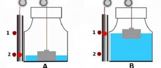
Single-tube differential pressure gauges are usually used when highly accurate results are required. In such devices, a wide vessel is used, which is subject to pressure with the highest coefficient. The only tube is fixed to a plate with a scale showing these differences, and communicates with the atmospheric environment. In the process of measuring pressure differences, the lowest pressure interacts with it. The working medium is poured into the differential pressure gauge until the zero level is reached.
Under the influence of pressure, a certain proportion of liquid flows into the tube from the vessel. Since the volume of the working medium that moved into the measuring tube corresponds to the volume that left the vessel, a single-pipe differential pressure gauge provides for measuring the height of only one liquid column. In other words, the measurement error is reduced. However, devices of this type are not free from shortcomings.
Deviations from the optimal values may be due to temperature expansion in the measuring components of the device, the density of the working medium and other errors, which, however, are characteristic of all types of differential pressure gauges. For example, a digital differential pressure gauge, even taking into account corrections for density indicators and temperature coefficients, also has a certain error threshold.
Differential pressure gauge: types, principle of operation
Liquid level control relay. operating principle and connection diagram
A differential pressure gauge is a device that is used to measure pressure drop. It can be used to measure the level of liquid in containers with increased pressure. This class of pressure gauge can be used to determine the flow rate of liquid or gas. The differential pressure gauge has another name - a pressure difference sensor.
As an example, we can consider a differential digital pressure gauge DMTs 01m. This product is used to measure pressure in a working environment. It is quite often installed in supply and exhaust ventilation systems. The pressure gauge provides calculations of gas flow parameters, including speed and flow rate.
This product is capable of calculating the parameters of gas flows removed from the source of pollution. Depending on the parameter being measured, the following types of products are distinguished:
- drop meters;
- flow meters;
- level gauges
Differential pressure gauges are widely used in technological processes to measure, control, record and adjust the pressure drop, flow rate of the working fluid and its level.
A flow meter is a product that is used to measure the flow of working fluid (liquid, gases, steam), using the principle of pressure drop across a constricting diaphragm or nozzle. The flow meter displays measurement results in l/hour, m3/hour, etc.
The differential meter is used to measure the difference in pressure of the working medium at two measurement points of the technological process. It shows the measurement results in Pa, bar, etc.
A level gauge is used to measure the level of a working fluid based on the size of its column. This product shows measurement results in length units - cm, mm, m.
In addition to what they can simply show, some modifications can send corresponding signals and can be equipped with a remote information transmission device UDPI.
The key difference between these devices is that it is able to record two values at once. The difference between them is displayed on the pressure gauge panel. But the actual characteristics do not always play an important role. It is enough to set a threshold value when it is reached, the pressure gauge will generate a control signal and send it to its destination.
Methods for obtaining parameters depend on the type of pressure gauge, in particular, on which sensitive element is used to obtain information. There is also a difference in the method of displaying the received information.
The principles of operation of pressure gauges come down to deformation processes occurring in measuring blocks, for example, in a bellows. This part is a pressure indicator that senses pressure surges. The block plays the role of a pressure converter. The user of this measuring instrument receives data on the measurement result in the form of moving an arrow on the display panel. As a rule, the measurement result is shown in Pa.
Differential pressure gauge device
Most models contain a whole complex of pressure gauge parts, functional components and tubes for communication between media. It is also mandatory to have several measuring chambers, which are separated from each other by manometric devices. In a typical operating scheme, these devices perform the functions of a sensitive element that records the pressure difference. A change in state with an oscillation of one or another characteristic in one of the media gives a signal and the indication mechanism is activated. Again, the means of expressing data for a differential pressure gauge differ, as do the reactions to changes in the system in principle. The device body is made of protected materials - high-strength plastic or metal with an anti-corrosion coating. The housing may also have special elements for installation, transportation or location in viscous and aggressive environments. The presence of such additions is especially important for device models that are used in the chemical industry.
Application of the maximum pressure drop indicator.
Vehicle diagnostic devices
The control arrow for the maximum pressure drop (tracking pointer) is an additional arrow on the instrument scale, which serves to indicate the maximum achieved differential pressure of the medium during operation of the device. The main indicator arrow of the device has the ability to move the control arrow in the direction of increasing pressure as the pressure drop increases. When the pressure drop decreases, the main arrow of the device returns towards lower values, and the control arrow remains at the maximum value achieved. To set the maximum value indicator arrow to the zero position, this indicator has a handle located on the outside of the instrument scale.
Differential pressure gauge with control arrow for maximum pressure drop
At remote sites where there is no permanent technological staff, a filter element may break through. The operator, during his next visit to the site, will record a zero pressure drop and may erroneously conclude that the filter is in satisfactory condition. Without a control needle, it is impossible to accurately analyze previous readings, so it is recommended that all devices intended for local indication be equipped with this option.
Basic classifications
Most differential pressure gauges contain a set of components and parts. With their assistance, communication links between environments are maintained. The device must necessarily include cameras, which are separated from each other by a device, with the help of which measurements are taken. That is, these devices play the role of a sensitive component, which records the pressure difference.
For the manufacture of the housing, polymers or metal with an anti-corrosion coating are used. The housing is equipped with special components that are used for transporting and securing devices at the workplace.
First, we need to separate out the small design differences between different pressure gauges. In practice, stationary and portable devices are used. The first ones are recorded directly at the place where the measurement was taken. The latter are used when examining a particular technological process.
Based on the method of data supply, the following modifications of the device can be distinguished.
Switch
This is the classic representation of analogue measurement products. The resulting value is shown by an arrow moving along the established scale. Such models are highly reliable, but in terms of accuracy, analog pressure gauges are significantly inferior to digital ones.
Digital pressure gauge
This device displays measurement results on the installed monitor. Such products can be equipped with a microchip, which is used to generate commands sent to the actuator. Pressure gauges of this class are installed directly into production lines. The actuators are controlled using electrical signals from 4 to 20 mA.
Diaphragm differential pressure gauge
At the base of this type of differential pressure gauge is a plate made of metal or other elastic material. Sometimes, to increase the efficiency of membranes, they are made corrugated.
The differential membrane device includes two containers designed to measure the parameters of the working fluid. The containers are interconnected by a block, equipped with impulse tubes. The pressure difference can be fixed using a rod. It is connected to the measuring organ. With extreme fluctuations, the rod causes changes in the signal at the output of the device. This guarantees the display of the resulting parameters.
Bellows differential pressure gauge
A differential pressure gauge of this class is often called an indicating gauge. Structurally, it consists of an indicating and bellows part. The display part is a round body. A pointer-type indicator mechanism is installed inside it. The division price of such a device is 1 mbar. Bellows pressure gauges have found their application in heating and water supply systems. In addition, they are installed in gas supply complexes through which neutral gases are transported.
In the working part of the differential pressure gauge, elements of elastic mechanics are installed; they consist of bellows, springs, etc. That is, the active medium affects the damping system, which in turn transmits signals to the indication system. Devices of this class are distinguished by high measurement accuracy, since the mechanics are not susceptible to the effects of temperature and moisture
Mercury differential pressure gauge
It is distinguished by its complexity of design. The operation of this product is based on determining hydrostatic characteristics using a mercury column. Using interacting vessels, the device records pressure differences by assessing and comparing excess levels in liquid columns.
The peculiarity of devices of this type is the density of the working fluid. This minimizes the effect of capillary forces.
Mercury differential devices are distinguished by high sensitivity to temperatures. Therefore, to eliminate temperature effects, adjustment devices are installed on them.
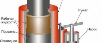
Design features and device
The basis of the working group of the pressure difference meter is a sensitive metal plate or other elastic element. In some cases, to increase sensitivity, the membranes are made corrugated.
Differential pressure gauge includes:
- leash
- lever arm
- two sealed chambers (“plus” and “minus”) for measuring pressure.
The chambers are connected to each other using a valve block. The pressure difference is recorded by the core rod connected to the sensing element. When oscillating, it leads to a proportional change in the output signal. This creates an indication effect.
Photo - appearance of a membrane differential pressure gauge
Water pressure in the water supply
Low pressure level
With a fairly low pressure, which is manifested by a fairly weak water supply directly from the tap and indicates a completely low level. A fairly pressing and common problem is for residents of upper floors, as well as owners of country houses. Low pressure in the water supply will prevent many necessary household appliances from working, which will become a significant problem, and there will also be a desire to correct this situation.
Carrying out installation work to install equipment that can increase this indicator is a fundamental technique for ensuring a solution to this issue. Naturally, before using modern units designed for these purposes, it is necessary to determine whether the system is clogged, which may also be one of the reasons for this phenomenon.
In a certain way, this problem can be completely eliminated with the help of a specialized pumping unit, which will help increase the pressure, or by modernizing the system itself by integrating the pumping station with the storage tank.
Naturally, a more rational and suitable method should be determined directly by the owner himself, which is determined by the goals being pursued, as well as the necessary volumes of liquid that will be required to fully provide the home.
Advantages of differential pressure gauges.
The use of differential pressure gauges allows you to accurately determine the condition of the filter elements. There is no need for scheduled replacement, in which there is a possibility of finding the filter in good condition. Replacing filter elements is a rather labor-intensive process, often requiring a stop in production, and therefore leading to losses
This is why it is so important to replace filters only when clearly necessary.
For integration into a control system, the devices can be additionally equipped with current outputs or signaling contacts. This option is especially useful for filters with forced cleaning capabilities, as it allows you to automate the process. If clogged, the sensor will signal the system about the need for backflushing, for example, in the case of air filters at the inlet of a gas generator (gas turbine).
As a replacement for a differential pressure gauge, you can use two ordinary pressure gauges. In this case, the measurement error increases, since it is equal to the sum of the errors of each device. In addition, there is a risk of error when manually calculating the pressure difference. In the case of low pressure drop values, this method will require the use of pressure gauges of a high accuracy class and, accordingly, high cost in relation to the option of using a differential pressure gauge.
| Model 522 Differential Pressure Indicators | Differential pressure gauge model 240 |
There are models with a simplified color scale, the so-called differential pressure indicators.
Application area.
|
|
Operating principle and equipment classes
There are various systems, in different blocks of which different pressures are pumped. This is not just about global heating systems. The same conditions arise at an oil refinery or gas transportation station.
Moreover, to maintain the functionality of the system, there is no need for an accurate understanding of the pressure in the various chambers of the system. You only need to know the magnitude of its change.
This is exactly what the differential pressure gauge shows. Below are the various designs. They all serve the same purpose:
- bellows;
- pneumatic;
- diaphragm.
It is worth noting that the first type is the most common. The difference in pressure of the working chambers, which appears on the bellows block of the differential pressure meter, is converted into an electrical signal.
In the future, it can be used in different ways: displayed on the device display or transmitted to the control center for further decision-making.
Mercury differential pressure gauge
It is part of a wide group of liquid pressure gauges, having one of the most technically complex designs. The principle of operation of the device is based on determining hydrostatic pressure indicators in a column of liquid - in this case, mercury. Also using a system of interaction of communicating vessels, the device determines the pressure difference by recording and comparing excess levels in liquid columns. The features of mercury differential pressure gauges include the high density of the working medium, which minimizes the negative influence of capillary forces.
In addition, to protect the working process from external influences at a static pressure of up to 5 MPa, additional elements for controlling the initial position of the serviced liquid column can be used. In addition, mercury differential pressure gauges are sensitive to temperatures, therefore, to eliminate the effect of thermal influence, the devices are sometimes equipped with means for adjusting the zero level of the sensitive medium.
Classification
Due to the complexity of pressure measurement processes, fluid characteristics and further conversion, there are several options for differential pressure gauges to work under different conditions. By the way, a differential pressure gauge, the principle of operation of which is largely determined by its design, is oriented in its design to the possibility of use in specific environments - therefore, the classification is based on this. So, manufacturers produce the following models:
- A group of liquid differential pressure gauges, which includes float, bell, pipe and ring modifications. In them, the measuring process takes place based on indicators of the liquid column.
- Digital differential pressure gauges. They are considered the most functional, since they make it possible to measure not only the characteristics of pressure drops, but also the speed of compressed air flows, humidity and temperature indicators. A prominent representative of this group is the Testo differential pressure gauge, which is also used in environmental monitoring systems, aerodynamic and environmental studies.
- Category of mechanical devices. These are bellows and diaphragm versions that provide measurement by monitoring the characteristics of the pressure sensitive element.
Purpose of a membrane differential pressure gauge
To monitor the pressure indicator and measure differences, special devices are used - differential pressure gauges. Unlike a simple pressure gauge, which measures the pressure at a selected point, a differential pressure gauge uses the difference in pressure at two measurement points.
There are many types of differential pressure gauges, the most common of which is diaphragm. This is a measuring kit consisting of several components:
- a primary sensor device that connects to the restriction device;
- 1-2 secondary devices.
Remote communication between the sensor and the secondary device occurs electrically. Devices with sensors that are equipped with elastic and flaccid membranes are often used.
Principle of operation
In most pressure gauges, the technology for determining and calculating data is based on deformation processes in special measuring units, for example, in a bellows unit. This element acts as an indicator that senses pressure changes. The block also becomes a difference converter in pressure indicators - the user receives information in the form of moving the pointer arrow on the device. In addition, data can be presented in Pascals, covering the entire measurement spectrum. This method of displaying information, for example, is provided by the Testo 510 differential pressure gauge, which during the measurement process eliminates the need for the user to hold it in his hand, since there are special magnets on the back of the device.
In mechanical devices, the main indicator is the location of the arrow, controlled by a lever system. The pointer moves until the changes in the system cease to exert a certain force. A classic example of this system is the DM 3538M series differential pressure gauge, which provides proportional delta (pressure difference) conversion and provides the result to the operator in the form of a unified signal.
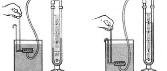
Two-pipe models
These devices are used to measure pressure indicators and determine the differences between them. These are devices with a visible level, which is usually presented in a U-shape. By design, such a differential pressure gauge is an installation of two vertical communicating tubes, which are fixed on a wooden or metal base. An obligatory component of the device is a plate with a scale. In preparation for measurement, the pipes are filled with a working medium.
Next, the measured pressure begins to flow into one of the pipes. At the same time, the second pipe interacts with the atmosphere. During the delta measurement process, both tubes experience the measured pressure. A two-pipe differential pressure gauge with liquid filling is used to measure vacuum, pressure of non-aggressive gases and air media.
Testo models
is one of the leading developers of measuring and metrological devices. The differential pressure gauge segment is represented by several series, which are used in ventilation systems, gas pipelines, boiler automation and other equipment. Among the most popular models of this brand is the Testo 510 differential pressure gauge, operating in the range from 0 to 100 hPa. The device is quite simple, both in physical handling and in managing electronic functionality. There are magnets on the surface for easy installation, and through the ergonomic operating panel the user can configure the device for different measurement modes, also connecting means of compensation for temperature and air density.
Recommended models:
| Model | Error | Differential pressure range | Operating pressure | Electrical options |
| ±2% | From 0-5 PSID (0-0.35 bar) to 0-110 PSID (0-7 bar) | 6000 PSID (400 bar) | Signaling contacts | |
| ±2% | From 0-5 PSID (0-0.35 bar) to 0-110 PSID (0-7 bar) | 6000 PSID (400 bar) | Signaling contacts, 4-20 mA current output | |
| ±5% | From 0-5 PSID (0-0.35 bar) to 0-110 PSID (0-7 bar) | 3000 PSID (200 bar) | Signaling contacts | |
| ±2% | From 0-20″ H20 (0-50 mbar) to 0-100 PSID (0-7 bar) | 1500 PSID (102 bar) | Current output 4-20 mA | |
| ±2% or 5% | From 0-25 PSID (0-1.7 bar) to 0-100 PSID (0-7 bar) | 3000 PSID (200 bar) | Current output 4-20 mA | |
| ±2% | From 0-20″ H20 (0-50 mbar) to 0-25 PSID (0-1.7 bar) | 3000 PSID (200 bar) | Current output 4-20 mA | |
| ±5% | From 0-50″ H20 (0-125 mbar) to 0-30 PSID (0-2.0 bar) | 1000 PSID (69 bar) | Signaling contacts | |
| ±5% | From 0-5 PSID (0-0.35 bar) to 0-50 PSID (0-3.5 bar) | 1000 PSID (69 bar) | Signaling contacts |
You can check the current price and buy differential pressure gauges for filters by contacting us using the contact coordinates indicated on the Contacts page or by filling out the “Write to us” contact form located on the right side of the current page of this site.
You can get acquainted with other models on the Differential pressure gauges page.
Principle - action - differential pressure gauge
The operating principle of differential pressure gauges is based on electrical force compensation of the force developed by the membrane under the influence of the measured pressure difference.
The principle of operation of differential pressure gauges is based on the use of the deformation of a bellows block, which perceives the measured pressure difference and converts it into angular movement of a pointer or pen using a lever transmission mechanism. The pointer or pen is rotated until the force caused by the pressure difference is balanced by the elastic deformation forces of the two bellows and the helical counter springs of the block and the torsion outlet tube.
| Diagram of a membrane differential pressure gauge with a pneumatic system for transmitting readings. |
The operating principle of a differential pressure gauge is based on converting the pressure difference of the measured medium into a proportional value of compressed air pressure.
| Diagram of external electrical connections of DM DPF pressure gauges with a secondary EPID device. |
The operating principle of the differential pressure gauge is based on converting the measured pressure into a proportional value of the compressed air pressure supplied to the device.
The principle of operation of differential pressure gauges with a metal membrane is to measure the elastic deformation of the membrane that occurs under the influence of the pressure difference in the cavities separated by this membrane. The movement of the membrane can be measured by various methods: mechanical, pneumatic, electrical.
The operating principle of the differential pressure gauge is similar to the previously described differential pressure gauge DKO.
| Diagram of external electrical connections of DM DPF pressure gauges with a secondary EPID device. |
The operating principle of the differential pressure gauge is based on converting the measured pressure into a proportional value of the compressed air pressure supplied to the device.
| Diagram of external electrical connections of differential pressure gauges DM with a secondary EPID device. |
The operating principle of a differential pressure gauge is based on converting the measured pressure into a proportional value of the compressed air pressure supplied to the device. The differential pressure gauge DMPK-100 works with secondary and control devices of the aggregate unified system (AUS), as well as with any secondary pneumatic device designed to change the input pressure from 0 2 to 1 kg/slg.
| Pneumatic membrane differential pressure gauge DMPK-100. |
The operating principle of the differential pressure gauge is based on compensation of the force developed by the elastic sensitive element of the measuring unit.
| Boiler heat shield.| Chamber diaphragm.| Scheme for measuring steam flow with a differential pressure gauge. |
2.4.3. Differential pressure gauges
Small values of differential pressure can be measured by devices based on elastic and flaccid membranes, bellows, as well as structures combined with other elastic elements. There are a sufficient number of designs, but they have their own characteristics.
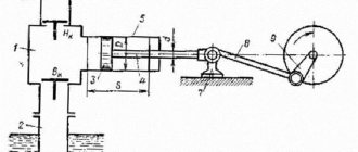
One of the simplest, most universal and widely used are differential pressure meters (differential pressure meters) with designs based on membranes and membrane boxes /2-18/. In one of the options (Fig. 2.73) the membrane box 1
, into which “positive” pressure enters through the inlet fitting of the holder
2
, is the sensitive element of the differential pressure gauge. Under the influence of this pressure, the movable center of the membrane box shifts.
| Rice. 2.73. Indicating differential pressure gauge based on membrane box: 1 – membrane box; |
“Minus” pressure through the inlet fitting of the holder 3
is fed inside the sealed housing
4
of the device and acts on the membrane box from the outside, creating resistance to the movement of its moving center.
Thus, the “plus” and “minus” pressures balance each other, and the movement of the moving center of the membrane box indicates the magnitude of the difference - differential pressure. This shift is transmitted through a transmission mechanism to the index hand 6
, which on the dial scale
7
shows the measured differential pressure.
The range of measured pressure is determined by the properties of the membranes and is limited, as a rule, from 0 to 0.4...40 kPa. In this case, the accuracy class is, as a rule, 2.5 or 1.5.
Mandatory structural tightness of the housing determines high protection from external influences and is determined mainly by the IP66 level.
Beryllium and other bronzes, as well as stainless steel, are used as materials for sensitive elements of devices; for fittings, transmission mechanisms - copper alloys, corrosion-resistant alloys, including stainless steel of various grades.
Devices can be manufactured in small (63 mm), medium (100 mm), and large (160 mm) diameter housings.
meters.
The disadvantages of differential pressure meters (differential pressure meters) based on a membrane box include high requirements for the tightness of the housing and small operating excess pressures, limited by the strength of the housing.
A differential pressure gauge with a vertical membrane (Fig. 2.74) consists of a “plus” 1
and “minus”
2
working chambers, separated by a sensitive corrugated membrane
3
.
4
attached to it .
The linear displacement of the rod in the transmission mechanism 5
is converted into an axial rotation of the tube and, accordingly, the index arrow, which reads the measured pressure on the instrument scale.
| Rice. 2.74. Diaphragm indicating differential pressure gauges with vertical diaphragm: 1 – “plus” camera; |
To maintain the functionality of the sensitive bellows membrane when the maximum permissible static pressure is exceeded, an opening safety valve is provided 6
. Moreover, the designs of these valves may be different. Accordingly, such devices cannot be used when contact of media from the “plus” and “minus” chambers is not allowed.
The high cost of the protective flanges of the membrane, as well as the difficulty of moving the center of this membrane beyond the pressure zone, lead to a relatively high cost of the product and, accordingly, its limited use.
In the design of an indicating differential pressure gauge with a horizontal membrane (Fig. 2.75), the linear movement of the center of the membrane is moved outside the measuring area using metal bellows.
| Fig.2.75. Diaphragm indicating differential pressure gauge with horizontal diaphragm: 1 – “plus” camera; |
Traditional plus 1 and minus 2 cameras, respectively, are placed in a single protective unit 3
, consisting of two parts, between which a corrugated membrane
4
.
A pusher 5 is fixed in the center of this membrane, transmitting movement from the membrane through sector 6
, trib
7
to arrow
8
.
In this transmission link, the linear movement of the pusher is converted into axial rotation of the arrow 8
, which tracks the measured pressure on the dial scale
9
.
This design uses a bellows system for removing the pusher from the working pressure zone. The separating bellows 10
with its base is hermetically attached to the center of the sensitive membrane, and with its upper part it is also hermetically attached to the inlet block. This design eliminates contact between the measured and the environment.
The design of the input block provides the possibility of washing or purging the “plus” and “minus” chambers and ensures the use of such devices for operation even in contaminated working environments.
In the design of a differential pressure gauge with a horizontal membrane, the additional installation of two metal bellows increases the reliability of the design, but significantly reduces its metrological characteristics.
A type of differential pressure gauge with a horizontal membrane and two metal bellows is the design shown in Fig. 2.76. Membrane 1 is fixed between two flanges 2 and 3. A pusher 4 is installed at the center of the membrane 1, the end of which is movably connected to the rocker arm 5. The displacement of the center of the membrane 1 through the pusher 4 is transmitted to the rocker arm 5, the movement of the end of which is an indicator of the magnitude of the measured difference. The separation of the zone of measured pressure from the external environment is carried out using an elastic seal 6.
Subsequently, the movement of the end of the rocker 5 to the index arrow is transmitted using a tribic-sector mechanism.
Positive pressure is supplied to input 7, negative pressure to input 8.
Rice. 2.76. Diagram of a membrane differential pressure gauge with an elastic outlet seal: 1 – membrane; 2 – lower flange; 3 – upper flange; 4 – pusher; 5 – rocker arm; 6 – elastic seal; 7 – positive input; 8 – negative input.
In the design of a membrane differential pressure gauge with an elastic outlet seal, the maximum operating excess pressure is determined by the properties of the rocker arm seal. The higher the mechanical properties of such a seal, the greater the operating excess pressure, but the worse the metrological characteristics.
A two-chamber differential pressure measurement system is used in the design of the device shown in Fig. 2.77. The measured flows of the medium are directed to the “positive” 1
and a “minus”
2
working chambers, the main functional elements of which are autonomous sensitive membranes.
The predominance of one pressure over the other leads to linear movement of the transmitting rod 3
, which is transmitted through the rocker arm
6,
respectively, to sector
4
, tribka
5
and the dial indicator system of the measured parameter.
Differential pressure gauges with a two-chamber measurement system are used to measure small differential pressures under not very high static loads, viscous media and media with solid inclusions.
The magnetomechanical principle of converting differential pressure into a reading system on a circular scale and organizing a control system, due to its convenience and simplicity of design, relatively low cost and high reliability, has been actively used in modern measuring instruments.
| Fig.2.77. Diaphragm two-chamber indicating differential pressure gauge: 1 – “plus” camera; |
The operating principle of a differential pressure gauge with a magnetomechanical signal conversion system/2-28/ is shown in Fig. 2.78. Rotating magnet 1
, at the end of which an arrow
2
, is placed in a housing
3
made of non-magnetic metal.
The mechanical piston 4 with a magnet attached to it, sealed with a fluoroplastic seal 5
, can move in the working channel
6
.
The mechanical piston 4
on the negative pressure side is supported by a plug
7
, which in turn is pressed by a range spring
8
.
Rice. 2.78. Diagram of a differential pressure gauge with a magnetomechanical transducer: 1
– rotary magnet;
2
– arrow;
3
– body;
4
– mechanical piston with a magnet attached to it;
5
– fluoroplastic seal;
6
– working channel;
7
– plug;
8
– range spring;
9
– block of electrical contacts.
The positive pressure medium acts on the mechanical piston through the corresponding supply fitting and moves it along with the plug 7
along channel
6
until such a displacement is balanced by counteracting forces - “minus” pressure and a range spring. The movement of the mechanical piston 4 with a magnet attached to it leads to the associated magnetic interaction with the angular movement of the rotary magnet 1 and, accordingly, the index arrow 2. Thus, the measured pressure difference is converted into the angular movement of the index arrow.
Coordination of the scale range with the angular movement of the pointer is achieved by selecting the elastic characteristics of the range spring 8.
In a number of designs, the fluoroplastic seal 5 is replaced with an elastic membrane, which increases the reliability characteristics of the device.
The differential pressure gauge with a magnetomechanical transducer has a block 9
, closing or opening the corresponding electrical contacts when passing near its mechanical piston with a magnet. The operating principle of such contacts is described in more detail in section 3.1.
One of the main design problems of differential pressure gauges operating at high excess pressures is the possibility of transmitting linear movement of the sensing element or part of it through the protective shell of the device. When measuring small pressure differences, the sensitive elements - these are, as a rule, membranes - develop very small adjustment forces, which structurally makes it difficult to transmit their linear movements through the protective shell of the device.
Devices with a magnetomechanical system for converting the linear movement of the piston into the axial rotation of the tube and an indicating arrow mounted on it ensure the transmission of the linear movement of the piston through the protective shell of the device through the interaction of magnetic fields and subsequent conversion into mechanical movement outside this shell.
Increasing the sensitivity of devices with a magnetomechanical conversion system is achieved by increasing the area of the element separating the “plus” and “minus” pressures. Such an element, which is a separator of different pressures and at the same time a primary converter, can serve as a membrane, as in the design shown in Fig. 2.79. The main elements of the system are identical to those presented in Fig. 2.78. The difference lies in the membrane 10, which separates the “plus” and “minus” pressures. The movement of the center of this membrane through the pusher 11 is transmitted to the piston with a magnet attached to it.
Fig.2.79. Diagram of a differential pressure gauge with a magnetomechanical transducer for measuring small pressure drops:
10
– membrane;
11
– pusher;
12
– plug.
Plug 12 is used for servicing the device, installing or changing the range spring.
Devices with magnetomechanical transducers are resistant to high static pressure - up to 40 MPa. At the same time, they provide measurement and control of differential pressure from 0 to 0.25 kPa...7 MPa with a relatively small error (about 2%).
The device body is made of non-magnetic metals such as stainless steel, Monel alloy, aluminum, copper alloys, synthetic materials. The material is selected based on operating conditions and properties of the measured medium. The seal material of the magnetic piston and membrane is also determined. It uses stainless steel (SS316,SS302) for the plug and range spring, nitrile rubber (Buna-N), fluorinated rubber (Viton) and ethylene propylene rubber (EPDM).
Varying the materials used in the design of devices ensures the applicability of such devices for various gases, including flammable gases such as propane-butane, media of different aggressiveness.
Models of devices with a magnetomechanical system in housings of 63, 80, 100, 150 mm provide indication functionality (display on a digital scale with a certain error) of the measured pressure difference, and can also be supplemented with electrical contact blocks in various designs. The designs of signaling groups of devices with magnetomechanical systems are described in more detail in Section 3.1.
As an example, Fig. 2.80 shows a view of a differential pressure gauge DP in a 63 mm housing (DP63).
Fig.2.80. View of a differential indicating pressure gauge with a magnetomechanical
converter
Active differential pressure gauges with a magnetomechanical converter are used to monitor clogging of filters on flow lines, the appearance of additional hydro- and aerodynamic resistance on operating equipment, including flow meters, shut-off devices, etc.
What is a differential pressure gauge?
One of the methods for monitoring and measuring the parameters of pneumatic and hydraulic systems in various technological processes is based on the use of pressure differences at measurement points.
Devices whose operating principle is based on measuring and using pressure differences are called differential pressure gauges or differential pressure gauges.
Unlike a simple pressure gauge, which measures the pressure at a selected measuring point, a differential pressure gauge uses the difference in pressure at two measuring points. The pressure difference creates an electrical signal in the device, or more precisely in its converter, reflecting the state of the system.
The resulting electrical signal is displayed on the operator screens through the conversion and linearization unit (BPL). In a simpler form, the signal is output to arrow indicators. That is, a differential pressure gauge can be considered as a device consisting of two parts, a converter and a UPL unit.
Digital differential pressure gauges
Devices of this type, in addition to the basic functions of measuring pressure differences, are capable of determining dynamic indicators of working media. Such devices are designated DMC-01m. A digital differential pressure gauge, in particular, is used in ventilation control systems for production facilities; it allows you to calculate gas consumption indicators, taking into account temperature adjustments, as well as keep track of average costs for measured items. The device is equipped with a microprocessor that automatically keeps records of measurements and accumulation of information on the gas duct. All information received about the results of work is displayed on the display.
Types of differential pressure gauges
Based on methods for measuring pressure differences, there are two large groups of differential pressure gauges.
Firstly, these are mechanical differential pressure gauges. They use a mechanical element that senses pressure differences, such as a membrane. A pressure gauge with a membrane is called a membrane differential pressure gauge. They are the most popular and widespread. You can see an example of the most typical membrane differential pressure gauge DM-3583M on the website adventex.ru/difmanometr-dm-3583m. Membrane instruments are used for measurements:
- consumption of steam, gas, liquid;
- liquid levels;
- difference between vacuum and excess pressure.
In addition to membrane mechanical differential pressure gauges, they produce devices with pressure sensing elements - membrane boxes and bellows.
Secondly, as opposed to mechanical differential pressure gauges, they produce liquid differential pressure gauges with sensing elements - a float, a bell, a hollow ring with a partition.
Diaphragm differential pressure gauges
The main subtype of mechanical differential pressure gauges, which is also divided into devices with metallic and non-metallic measuring elements. In devices with a flat metal membrane, calculations are based on recording the characteristics of deflections in the measuring component. A differential pressure gauge is also common, in which the membrane acts as a dividing partition for the chambers. At the moment of deformation, the counterforce is generated by a cylindrical spiral spring, unloading the measuring element. This is how two different pressure values are compared.
Also, some modifications of membrane devices are equipped with protection against unilateral influence - this design feature allows them to be used in measuring excess pressure indicators. Despite the active introduction of electronics into the metrology industry as a whole, membrane measuring instruments remain in demand and even indispensable in some areas. For example, a high-tech digital differential pressure gauge DMTs-01m, despite its ergonomics and high accuracy, has a number of limitations for use in conditions where the operation of membrane devices is possible.