Operating principle and general characteristics
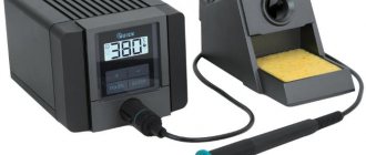
A soldering station, or sometimes called a machine or installation, is a device that is widely used in everyday life, in electronics, and electrical engineering. The main purpose of this equipment is group or single soldering of parts.
The design of this equipment includes the following components:
- A control unit that controls the operating parameters of the device.
- A soldering iron designed for soldering.
- Tweezers involved in the assembly/disassembly of elements installed on a printed circuit board.
- A hair dryer, which is designed to heat the assembly area. It can be used to perform both single and group operations.
- A heat source used to heat a printed circuit board to a process-specific temperature.
- A device for removing excess tin.
- Auxiliary equipment - stands, etc.
- Bracelets that relieve static tension.
Homemade soldering station
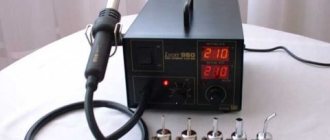
The simplest stations include soldering irons, a control device and soldering iron stands. The key difference between a station with a hair dryer and a traditional soldering iron is that the use of this machine allows you not only to connect parts together, but at the same time optimize the temperature regime. The station includes various devices that not only increase productivity, but also ensure worker safety.
And of course, we must not forget that soldering stations with a hair dryer are equipped with a device for removing static voltage.
The characteristics, as well as the operating principles of the station with a hair dryer, are not very complicated, and this allows you to build a soldering station with a hair dryer with your own hands.
Purpose of a homemade hair dryer
You need to have an accurate idea of what a soldering iron of this type is needed for. The device must create the melting temperature of tin in a certain place in the circuit. When melting the mounting alloy, a radio component is mounted or an unnecessary element is removed from the board of any electrical device.
The hairdryer creates a directed hot air flow to the place where the board circuit needs to be soldered. Under the influence of high temperature, tin turns into a liquid state, thereby enabling the worker to carry out the necessary installation operations.
Recommendations for assembling a homemade soldering station with a hair dryer
The key requirement that can be presented to a homemade soldering station with a hair dryer can be formulated as follows - it must provide an air flow heated to a temperature of at least 850 ⁰C. In this case, the power of the heating element in the soldering station should not exceed 2.6 kW.
In addition, all the components of this soldering machine with a hair dryer should not be expensive and should be affordable. By the way, household hair dryers do not meet any of these requirements. Most often, home craftsmen strive to make either a manual or stationary hot air gun.
Oddly enough, a stationary product is easier to assemble. This is due to the following reasons - no one limits the master in terms of size and weight characteristics. There is no need to manufacture a pistol grip, which is necessary to control the device.
Soldering hair dryer power supply circuit
A hot air gun, in a stationary version, works as follows - the heat emitter stands motionless on the work table, and the part needs to be moved. This solution leads to complications during soldering. To increase soldering efficiency, it is advisable to use a hand-held soldering iron (hot air gun). Such a device should be small in size and can be operated with unprotected hands.
One of the main questions that will confront a craftsman who decides to assemble a soldering station with his own hands is something like which heating tool is appropriate to use. As already noted, the components that make up a household hair dryer do not meet the requirements for devices of this type. Therefore, it is unacceptable to use them when creating a homemade soldering station.
The practice of creating homemade stations suggests that the best option is to make your own heater from nichrome wire. Its cross section should be in the range from 0.4 to 0.8 mm. It should be understood that using wire of a larger cross-section will provide a greater power reserve, but it will be quite difficult to obtain the temperature necessary for operation.
Nichrome wire heater coil
By definition, the heater should not be large. To do this, the heating coil should not exceed 4 – 8 mm in outer diameter. As a base on which the heating element will be fixed, it is necessary to use a material with high resistance to high temperatures. It could be ceramics. By the way, a part of this type, installed in a household hair dryer, may well be suitable.
A small fan can be installed as a supercharger. By the way, it can also be removed from an old hair dryer.
The fan should provide an air flow of 20-30 liters per minute. Another option is an air compressor for aquariums. To improve its performance, it is necessary to supplement it with a receiver. You can use an ordinary plastic bottle for it.
Making a body for a hair dryer can be done based on several options. You can use materials that show high resistance to temperature, for example, ceramics, but such a solution will make the structure more expensive. You can reduce the cost by using partial thermal insulation of the channel through which hot air moves.
Hot air gun body for soldering
For the body of a self-made hot air gun, you can use the body from a household appliance. There are some conditions - for example, the body must be sufficiently voluminous, and the nozzle must be made of heat-resistant materials or metals.
Another concern that the master will face is ensuring the operability of the device. In particular, the design of a homemade device must include a trigger mechanism (switch) and an element responsible for adjusting the air flow parameters, namely its speed and temperature. To solve these problems, rheostats must be installed in the electrical circuit, which allow smooth power adjustment.
The assembly of the product begins with the manufacture of a spiral. When winding it, it must be taken into account that its resistance should be in the region from 75 to 95 Ohms. The spiral must be wound on a reliable insulator, and the top must be covered with an insulator, for example, asbestos or fiberglass. After assembling this assembly, the ends of the spiral should come out.
The finished element must be installed in a previously prepared channel of the housing, that is, it must be lined with a layer of thermal insulation. After installing the spiral in place, it can be connected to the power wiring, which includes the switch.
IMPORTANT! When performing work, you must constantly remember thermal insulation.
An air heater must be mounted in the rear of the housing. If the dimensions of the supercharger do not allow it to be installed in the housing, then it is quite possible to secure it from the outside. An air duct must be connected to supply air.
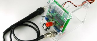
Hot air soldering station for Arduino
In this article we will learn how a DIYer made a hot air soldering station controlled by Arduino. In this project, the PID algorithm is used to calculate the required power and is controlled by the Triac driver. According to the master, this soldering station is efficient and reliable, and easy to assemble. Tools and materials: - Arduino Pro Mini; -1602 LCD module + I2C; -Rotary encoder with button; -Hair dryer for soldering station; -Hair dryer stand; - Triac BTA12-600B; -Transistor IRFZ44; -Amplifier MCP602; -Optocoupler MOC3021; -Optocoupler 4N25; -Diode bridge 2W10M; -Diode UF4007; -4-pin connector; -3-pin connector; -2-pin connector; -2-pin large connector; -Capacitor 0.1 uF; -Capacitor 10 nF; -Trimming resistor 200K; -Resistor 100K; -Resistor 47K; -10K resistor; -Resistor 1K; -Resistor 470E; -Resistor 330E; -Resistor 220E; -Resistor 39E; -Buzzer;
Further installation is as follows:
For LCD I2C Module I2C Module - Arduino Pro Mini GND - GND - GND VCC - VCC - 5V SDA - A2 - A4 SCL - A3 - A5.
For encoder module:
Encoder - Arduino GND - GND + - NC (not connected, the code uses the built-in arduino I/O) SW - D5 DT - D3 CLK - D4.
Hair dryer (7 wires) 3-pin connector - (green, black, red) Red wire - Thermocouple + Green wire - Reed switch Black wire - Common ground. 2-pin connector - (blue, yellow) Blue wire - Fan +0 Yellow wire - Fan - (or GND) 2 Large pin - (white, brown) White wire - Heater Brown wire - Heater (no polarity)
Step two: circuit diagram The circuit consists of 3 parts.
Interface part:
Consists of 1602 LCD display with I2C module and rotary encoder with button. The display shows the set temperature, current temperature, fan speed and applied power, as well as the current handle status. The encoder is used for various inputs and navigation through parameters and controls.
Sensor part:
Consists of a K-type thermocouple to measure temperature and reed switches to detect handle position. The thermocouple voltage is amplified by the op amp to a voltage level measured by the Arduino. The op amp gain is controlled by a 200K trimmer.
Controller part:
There are two controllers in this circuit. One of them is a simple PWM fan speed controller with a MOSFET. The other is an isolated controller for a heater. It consists of a TRIAC driven by an opto-coupled DIAC. The 4N25 optocoupler helps maintain synchronization with the AC signal.
Step three: printed circuit board The wizard recommends ordering a printed circuit board on the appropriate website, but if you wish, you can make it yourself. Arduino-Rework Station.sch Arduino-Rework Station.brd The board with specifications can be viewed here.
By rotating the encoder, the temperature and fan speed can be adjusted. A short press on the encoder switches between fan speed and temperature setting.
The hair dryer begins to heat up as soon as it is removed from the holder. The display shows “Ready”. When the set temperature reaches the set temperature, a short buzzer sounds. When you place the hair dryer in the holder, the heating stops, but the fan will continue to blow until it reaches a safe temperature. Once the temperature drops below 50 C, it will emit a short beep and display "COLD".
When the hair dryer is turned off, the controller will go into setting mode if the encoder is held down. Setup mode has options to calibrate, configure, save, cancel, and reset settings.
Note. If easyEDA PCB is used, change the reed switch pin number to pin number 8 and the buzzer pin number to 6.
You need to install the Commoncontrols-master, time-master and code libraries. hot_air_gun_station_V1.0.ino CommonControls-master.rar Time-master.zip You can download all the files in one zip file here.
Then go to setup mode and select “Calibrate”. Select the calibration point: 200, 300 or 400 degrees, press the encoder. The hair dryer will reach the desired temperature and the buzzer will beep. Rotate the encoder knob to enter the actual temperature. Then select another reference point and repeat this process for all calibration points.
After that, tap and go to the main screen and then go back to the setup mode and select save.
Source
Become the author of the site, publish your own articles, descriptions of homemade products and pay for the text. Read more here.
Rules of use and safety precautions
When working, you must strictly observe safety precautions and rules for using such devices. Firstly, fire safety must be observed.
During operation, it is unacceptable to suddenly change the temperature in the heating element.
During work, you must be careful and avoid touching heated elements. Moisture must not get into the body or inside the hot air gun.
Attachments can only be replaced after the hair dryer has cooled down.
The workplace must be well ventilated.
DIY soldering station diagram, element base
The key tool of a soldering station is the soldering iron. If, when assembling the station yourself, you can use some elements removed, for example, from household appliances that have expired. Then the soldering iron should be new without any dispute. Many craftsmen prefer Solomon products and some others.
Soldering station diagram
After selecting a soldering iron, you can begin to select a diode bridge for the electrical circuit and transformer. In order to obtain a voltage of 5 V, a linear stabilizer with good cooling is needed. As an alternative, you can consider using a transformer that has a winding available that is necessary to service the digital unit.
A schematic diagram of a homemade device can be found on specialized forums.
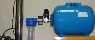
Power supply diagram
Schematic diagram of a UPS from a Kenon printer
If the power supply is in working order, the most important thing is to avoid the temptation of improvement and radical modifications. All you need to pay attention to is the SMD resistor R25 with a nominal value of 18 kOhm. First, unsolder it and solder two soft stranded wires in insulation 15 cm long onto the contact pads. And don’t touch anything else on the board.
Modification of the power supply for the cooler
But with this particular power supply, due to its recent malfunction, we had to deal with it less delicately - to be sure and fully understand its real functioning, we had to remove not only the SMD resistor R25, but also the trimming resistor VR21 and the output zener diode ZD21.
Useful: IR obstacle sensor with direction detection
Checking the power supply with a multimeter
The place of the trimmer was taken by a 4.7 kOhm variable, and instead of an 18 kOhm SMD resistor, a 22 kOhm variable resistor was installed. Having connected the electric motor of a hand drill to the load and driven it heartily, I set the 4.7 kOhm variable to such a position that the 22 kOhm variable resistor in the extreme left position of the slider produced 5 volts at the output, and in the extreme right position almost exactly 24 volts.
Purpose of buttons and firmware options
The front panel of the station must be equipped with control buttons responsible for performing the following functions:
- Lowering/increasing the temperature in a certain step, for example 5 or 10 degrees.
- Installation of pre-selected modes.
Setting up a soldering station
Instead of control buttons, you can use an external device (programmer) or perform firmware inside the circuit. Setting the temperature is quite simple.