12.12.2019 Author: VT-METALL
Issues discussed in the material:
- What advantages does the production of welded structures provide in comparison with other metal processing methods?
- What are the stages of production of welded structures?
- How defects in the production of welded structures are eliminated
The development of the production of welded structures has radically changed the mechanical engineering and construction industries. Riveted structures were almost everywhere replaced by welded ones. The next step was the development of gas welding.
Every year the pace of development of the production of welded structures is only growing. This growth is explained by increased consumer demand, because metal structures produced by welding have a number of undeniable advantages.
Advantages and disadvantages of producing welded structures
The main advantages of a welded structure include:
- seam quality and weld strength;
- ease of construction;
- reliability;
- ease of use;
- long period of use;
- production efficiency.
In addition to their advantages, welded structures also have some disadvantages, the main one being low corrosion resistance. This problem is solved by modern methods of metal production and processing.
Let's consider some features inherent in welded structures:
- During the manufacturing process, the metal parts of the structure are connected at the molecular level. The edges of the parts melt, turning into a liquid state, and exchange molecules. In terms of strength, such a product is as close as possible to a solid one.
- An important feature of welded structures is their lower cost compared to riveted or cast ones, which is achieved by saving metal. It can reach 20%, which significantly affects the final cost of the product. This leads to increased production profitability.
- Another feature is the ease of construction compared to cast or riveted ones, since less metal is used to manufacture the welded product. But its strength is higher than those of its analogues.
We recommend articles on metalworking
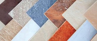
- Steel grades: classification and interpretation
- Aluminum grades and areas of their application
- Defects in metal products: causes and search methods
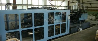
Basic equipment for the production of welded structures
To produce welded structures, welding equipment is required. It consists of: power supplies, auxiliary devices and a control unit. There are several types of such complex devices, differing in components.
Transformers - reduce (convert) the alternating current voltage, which is necessary to create an electric welding arc. The operation of such devices and their configuration depends on magnetic dispersion (increased or simple) and phase control - the characteristics of the transformer.
Rectifiers - are necessary to convert and reduce alternating current, this affects the evenness of the resulting weld and uniform strength. With a straightener, metal spattering is significantly reduced, which leads to a reduction in production time, since there is no need to clean the weld from the melt. Consisting of a block of semiconductor diodes, rectifiers work with any electrodes, welding all metals and their alloys.
An inverter is a network rectifier that smoothes alternating current. The resulting direct current enters the inverter. Then the high frequency transformer and power rectifier transmit direct current, which is stable and has high power. Such pieces of equipment allow you to fine-tune the equipment to work with any electrode and perform various tasks.
Semi-automatic devices are devices for working in a gas environment. The gas can be inert, such as argon or helium, as well as active, such as carbon dioxide, nitrogen or oxygen. The choice of gas used for the production of welded structures depends on the materials of the parts being connected. The electrodes are supplied to the connection point automatically, and the welding parameters are adjusted either manually or also in automatic mode. The use of semi-automatic machines in the production of welded structures increases the speed of work. One of the reasons for this is that there is no need to replace the electrode, which is supplied to the welding site automatically. This creates an even and high-quality seam. Basically, semi-automatic machines are used in production for large volumes of work.
Manufacturing technology and automation of production of welded structures
Home » Articles » Professionally about welding » Mechanization and automation of productionWe recommend purchasing:
Installations for automatic welding of longitudinal seams of shells - in stock!
High performance, convenience, ease of operation and reliability in operation.
Welding screens and protective curtains are in stock!
Radiation protection when welding and cutting. Big choice. Delivery throughout Russia!
The initial data for designing the technological process for manufacturing a welded structure are product drawings, technical specifications and the planned production program.
Blueprints
contain data on the material of the workpieces, their configuration, dimensions, types of welded joints - decisions that were made by the designer during the design process of the product and must be accepted for execution by the technologist. The technologist has no right to make changes to the drawings. Therefore, any deviation from the drawing must be preceded by its correction by the designer.
Specifications
(TU) for the production of a certain type; designs contain a list of requirements that apply to materials, equipment and the implementation of technological: and control operations. Specifications briefly outline the experience of design, manufacturing and operation accumulated in this industry. Therefore, when designing technological processes, it is necessary to comply with the requirements of the technical specifications. Deviation from them in each individual case must be sufficiently justified.
Release program
contains information about the number of products that need to be manufactured within a specific period (for example, per year). These figures serve as the basis for the selection of equipment, technological equipment and means of mechanization and automation.
In addition, according to the release program, the economic efficiency of this choice is assessed. The production process of products includes various technological, control and transport operations. The main requirement that determines the sequence of these operations, their content and provision of equipment is the implementation of a given program for the production of high-quality products in the shortest possible time at a minimum cost.
The sequence of performing the main assembly and welding operations is determined by the choice of the option of dividing the structure into technological units, subassemblies and individual parts. The optimality of such division is determined by the following considerations.
1. At the installation site, working conditions, the possibility of using high-performance equipment and quality control equipment are less favorable than at the factory. Therefore, it is advisable to separate large-sized products into transportable units that will minimize installation work.
2. From the standpoint of accessibility of welded joints, ease of their implementation and subsequent post-operative control, it is advisable to perform assembly and welding work by sequentially enlarging individual elements into subassemblies and assemblies with subsequent assembly of the entire product. This alternation of assembly and welding operations facilitates the use of high-performance welding equipment, but with low rigidity of individual components it can lead to an increase in deformations from welding.
3. To assess the expected welding deformations and select a rational sequence of assembly and welding operations, calculation methods should be used.
4. The required accuracy of the dimensions and shape of the welded product should be ensured by the rational construction of the technological process and the use of straightening work at the stage of procurement of elements and assembly and welding of individual components. Editing the finished product is, as a rule, extremely labor-intensive.
5. Heat treatment of the entire structure can significantly complicate the manufacturing process, especially in conditions of serial and mass production. Therefore, if it is necessary to improve the mechanical properties, relieve residual stresses or stabilize dimensions in any zone of the structure, it is advantageous to choose an assembly and welding sequence that allows local or preliminary heat treatment of individual subassemblies or parts.
The development of technology aims to provide optimal conditions for performing each individual operation and the entire process as a whole. Since for different types of welded structures ideas about the optimality of the technological process can differ greatly, considerations about the rational design of the manufacturing process will be discussed in detail in the chapters devoted to typical welded structures. However, the requirement to save manual labor is common and has become increasingly urgent over the years. The Constitution of the USSR speaks of the need to reduce, and subsequently completely eliminate, heavy physical labor on the basis of comprehensive mechanization and automation of production.
Under the mechanization of the production process
understand the replacement of manual labor with machine work. In an automated process, service personnel perform only the functions of setting up and monitoring the operation of instruments and control systems. The control system consists of mechanisms and means of communication that ensure precise and time-coordinated interaction of working and auxiliary units and devices.
In the field of welding production, labor costs for the actual welding work
usually do not exceed 30%.
A large volume is occupied by procurement, assembly and auxiliary, especially transport, operations. Consequently, increasing the productivity of welding work alone cannot provide a significant effect. Hence the need for comprehensive mechanization and automation, covering the entire production process, including not only the main ones (procurement, assembly, welding, finishing), but also auxiliary (transport, control) operations. Improving the production of welded structures requires not only the presence of mechanisms capable of carrying out all the necessary operations of the technological process, but also their rational layout. At the same time, the requirements for both the mechanisms and their layout are determined by the nature of production. Thus, for single and small-scale production, universal devices are required that are suitable for working in a wide range of standard sizes of workpieces and products, while for large-scale and mass production, specialized equipment is required, on the basis of which production and automatic lines for specific purposes are created. Taking into account the feasibility of increasing the serial production of manufactured products through typification and unification, we can identify the main directions for improving the production of welded structures
.
1. Increasing the serial production of manufactured products by finding progressive design forms and technologies that meet the conditions of a continuous and synchronous production cycle.
2. Creation and centralized production of special technological equipment capable of ensuring the efficiency of such production.
3. Creation of universal devices for complex mechanization of processes in individual and small-scale production.
The vast majority of equipment for production and automatic lines of welding production in the USSR is manufactured by industry ministries in non-specialized production conditions. This limits the capabilities of domestic organizations, and if it is necessary to create new continuous and automatic welding production lines, for example in the automotive industry, it is necessary to resort to purchasing equipment abroad. In other countries, more attention is paid to the creation of such equipment. This is manifested in the merger of welding companies with companies producing computer-controlled machines. The experience of machine tool builders in this area contributes to the improvement of welding equipment and allows us to find new solutions. An example of this is the creation of industrial robots. For welding production, the use of robots will apparently serve as the main means of solving the problem of saving labor resources. The versatility of robots allows them to be designed and manufactured in specialized organizations in large series. The use of robots in the production of welded products can eliminate the need for each automatic line to design and manufacture complex specialized equipment. In serial, and even more so small-scale production, the versatility of robots turns out to be especially useful due to the relative ease of transition from the production of one type of product to another.
The efficiency of a production line served by devices that automatically perform individual operations can be significantly increased with the help of a computer. On their basis, group control systems for a large number of mechanisms are created to automate not only the main, but also auxiliary operations. By introducing feedback, a group control system from a central computer makes it possible to organize quality control of technological operations with compensation for emerging distortions in technological modes. It is also possible to organize operational monitoring of equipment condition in order to increase the reliability of line operation. For example, redistributing the functions of a broken robot among other robots allows it to be repaired without stopping the line, only slightly reducing its productivity. The use of group control of units using a computer reflects one of the basic principles of using automatic control systems (ACS) - ensuring complete and effective automation of production processes.
Source: Nikolaev G.A. “Welded structures. Manufacturing technology. Automation of production and design of welded structures"
Stages of a typical technical process for the production of welded structures
The production of welded structures is a technological process, divided into certain stages and requiring an integrative approach. Complexity lies not only in the welding process itself (methods and modes), but also in the creation of new materials that increase the reliability of the structure at the joints. For example, the development of new grades of steel for use in industry (they are ideal for the production of welded products) or new processes for calculating and connecting welded structures, adapting them to current tasks.
The technology of welding products includes the creation of modern materials and equipment, as well as research and testing of joining processes that will increase production efficiency. The reason is the development of various areas of construction and production, they pose new tasks and more and more complex structures are developed for them.
New products require the use of different welding methods: manual arc, automatic or semi-automatic. Using flux or shielding gases... Welded joints can also vary: there are T-joints, corner joints, butt joints, end joints, etc.
The production process of a welded structure begins with its calculation and preparation of technical documentation.
This is followed by obtaining parts suitable for a given product, preparing them for welding, joining them into a structure, processing after welding: heat treatment, straightening, machining. At the last stage - control of welding places. All of the listed stages of the welding process are important and interconnected. They ensure the quality of the manufactured product with the specified properties. This whole process is called welding production, which is organized in accordance with the characteristics of various branches of mechanical engineering.
Another essential stage of production is the preparation of workpieces for welding. We are talking about their edges; they are processed at an angle manually - with a file or mechanically, as well as with a grinding machine. Not only the fact of processing is important, but also the form. The X-shaped one is considered the most effective, since it contributes to the least amount of metal deposition during connection. Accordingly, the quality of the seam increases.
MDK. 02.05. Manufacturing technology of welded structures
Slide 1
Pipeline welding technology Lesson plan: Definition and classification Large diameter pipelines Pipelines from finished pipes Welding of rotary pipe joints Welding of non-rotary pipe joints Technological joint (operational)
Slide 2
(I) Definition and classification Pipelines are devices that are continuous lines of pipes, with various fittings, designed for transporting liquid, gaseous and bulk products.
Slide 3
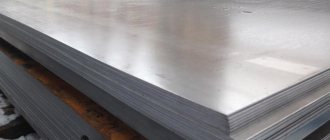
All pipelines are divided into: main (long) pipelines; technological (complex shape). According to their structural structure, they are distinguished: large-diameter pipelines made of sheet steel; medium and small diameters from finished pipes.
Slide 4
Pipelines made from prefabricated pipes operate at various pressures and heating temperatures. If the working pressure in pipelines is less than 0.07 MPa, then the rules of Rosgortekhnadzor do not apply to them. Pipeline joints for pressures above 0.07 MPa are made only by welders certified for this work. Each welded joint must have a welder's mark.
Slide 5
(II) Large diameter pipelines Welding large diameter pipelines has much in common with welding tank structures. These pipelines are welded using longitudinal and transverse seams from shells that are pre-rolled from sheets. Such pipelines operate under pressure up to 0.07 MPa and are not subject to inspection by Rosgortekhnadzor.
Slide 6
The main requirement for the welds of these structures is their density and gas tightness. Sometimes, to increase the rigidity of the gas pipeline, ribs from angles, T-bars or channel bars are welded on the outside.
Slide 7
(III) Pipelines from prefabricated pipes Pipelines welded from prefabricated standard pipes usually operate under elevated pressure. In main pipelines the pressure is 60-70 kgf/cm2. In pipelines of petrochemical plants, the operating pressure reaches 500-700 kgf/cm2.
Slide 8
For such pipelines, only transverse butt seams are welded with a V-shaped groove of the edges. When welding the root of the seam from the inside is not possible, backing rings are used. They are made of steel grades st2 or st3, thickness 1.5-3mm, width 30-50mm. The edges of the pipes are processed for welding at the manufacturer.
Slide 9
Welding the backing ring to the first (a) and second (b) pipes
Slide 10
It is not recommended to use welding on the remaining backing ring in critical pipelines and operating in aggressive environments, since the presence of a gap between the backing ring and the pipe wall can cause corrosion in this place. The main types and structural elements of seams in welded joints are established by GOST 16037-80 for steel pipelines and GOST 16038-80 for copper and copper-nickel pipelines.
Slide 11
When assembling joints, it is necessary to ensure that the gap around the entire perimeter of the joint is uniform and that the edges in the joint coincide. The size of the gap should ensure complete penetration of the root of the seam. The difference in wall thicknesses should not exceed 10% of the wall thickness, but not more than 3 mm.
Slide 12
Allowable displacement of pipe ends during assembly for welding Wall thickness, mm 3-4 5-7 7-8 9-14 15 and more Displacement no more than, mm 1.0 1.5 2.0 2.5 3
Slide 13
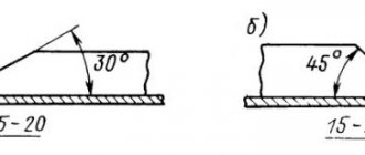
Types of preparation of edges for pipes depending on the thickness of the metal and type of welding (GOST 16037-80) Name of parameters Value Pipe wall thickness, mm: - without bevel for manual arc welding - without bevel for gas welding - with one-sided bevel at an angle of 30±3º for manual arc welding - with one-sided bevel at an angle of 30±3º for gas welding 2-4 1-3 3-20 4-7 Pipe wall thickness, mm: 1.6 2.3 3-8 8-20 Gap between edges, mm: - for manual arc welding - for gas welding — 0.5 0.5 1 1 — 2 —
Slide 14
Scheme for checking the perpendicularity of pipe ends
Slide 15
Nominal outer diameter of a pipe, fitting or branch pipe, mm From 530 to 630 More than 630 Permissible skew of plane “e”, mm 5.0 6.0 Electric-welded pipes Electric-welded pipes Seamless pipes Nominal outer diameter of a pipe, fitting or branch pipe, mm Up to 76 inclusive 77 -133 134-245 246-325 326-630 631-720 More than 720 Permissible skew of plane “e”, mm 0.5 1.0 2.0 2.5 3.0 4.0 5.0
Slide 16
Methods for processing pipe ends when joining elements with different internal diameters a) spreading (without heating or with heating) the end of a pipe with a smaller internal diameter b and c) mechanical processing (boring) along the inner surface of the end of a pipe with a smaller diameter d) surfacing on the inner the surface of a pipe having a larger internal diameter, a layer of metal, followed by processing it with a cutter or an abrasive stone to remove irregularities and ensure a smooth transition to the surface of the pipes. This method can be used for pipes with a diameter of 159 mm or more made of carbon and low-alloy steels of the pearlitic class.
Slide 17
Centralizers of various designs are used for assembly. The assembly is fixed with tacks made of high-quality (main) electrodes. According to the standards, tacks with a length of 30-40 mm and a height equal to half the wall thickness are applied.
Slide 18
The technique for welding pipeline joints is adopted depending on the diameter of the pipe, the thickness of its wall and the chemical composition of the metal. Rotary and fixed joints of pipelines are welded using various technological methods.
Slide 19
Manual welding of pipe joints with coated electrodes is used when applying a root weld without backing rings, as well as in the manufacture and installation of pipelines in conditions inconvenient for mechanized arc welding: joints of an elbow-shaped bent pipeline, joints of a pipeline passing through natural barriers (water, mountains, etc.) , connecting sections into long strings, welding flanges, plugs, etc.
Slide 20
The root seam is made with 1.6-3 mm electrodes, depending on the thickness of the pipe wall, and the remaining seams can be made with more productive types of welding (automatic or semi-automatic). When manually welding the entire joint, it is advisable to perform it in several layers: - with a wall thickness of 4-5 mm - in two layers (not counting the root one), - with 10-12 mm - in four layers with electrodes with a diameter of 3-4 mm. Manual gas welding is performed in only one layer.
Slide 21
(IV) Welding of rotary pipe joints Manual arc welding should be performed with as short an arc as possible, especially when using electrodes with a basic coating, for which the arc length should be no more than the diameter of the electrode. During the welding process, it is necessary to break the arc as little as possible. Before extinguishing the arc, the welder must fill the crater by gradually withdrawing the electrode and bringing the arc back 15-20 mm onto the weld just made. Subsequent ignition of the arc is carried out at the edge of the pipe or on the weld metal at a distance of 20-25 mm from the crater.
Slide 22
To avoid slagging of the weld metal near the edges of the pipes, a bead that can be as flat as possible should be deposited. Upon completion of surfacing of each bead, it is necessary to completely remove the slag after it has cooled (darkened). If defects (cracks, accumulations of pores, etc.) are detected on the surface of the weld, the defective area should be removed mechanically to the “healthy” metal and, if necessary, welded again.
Slide 23
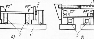
To reduce welding stresses and deformations, a certain procedure for manual arc welding of rotary joints of pipes with a diameter of 200-600 mm is used. The pipe joint is connected by three symmetrically located tacks. The circumference of the joint is marked for welding into four sections.
Slide 24
The procedure for welding pipe joints with rotation: a – placement of tacks (1) and weld sections (A, B, C, D); b – execution of the first layer in sections A-B and D-C; c – turning the joint and making the first layer in sections G-A and B-B; d - making the second layer of the seam through; d – making the third layer of the seam in the opposite direction.
Slide 25
The first layer is welded with an electrode with a diameter of 4 mm at a current of 120-150 A with a narrow roller in the direction from bottom to top, and then, turning the pipe 90°, the last opposite sections of the first layer are welded. After this, using an electrode with a diameter of 5 mm at a current of 200-250 A, a second layer is applied in one direction and a third layer in the direction opposite to the second layer. The first layer is the most responsible because it should ensure complete penetration of the root of the seam.
Slide 28
Scheme for applying “locks” of seams In all cases of multilayer welding, it is necessary to break the seam into sections in such a way that the joints of the sections (“locks” of seams) in adjacent layers do not coincide, but are offset from one another, and each subsequent section overlaps the previous one. The displacement and overlap size “a” (for automatic submerged arc welding should be at least 50 mm, for all other welding methods - 12-18 mm).
Slide 29
Assembly and welding of a rotary joint
Slide 30
(V) Welding of non-rotating pipe joints Welding of non-rotating joints (installation) with a diameter of 200-600 mm is carried out when rotation around an axis is not possible.
Slide 31
The procedure for welding joints of fixed pipes: a – assembly of pipes on tacks; b, c, d – execution of the first, second and third layers; A, B, P – boundaries of sections of the first layer of the seam; T, K - the same for the second layer of the seam; 1-7 – sequence of seam layers in sections.
Slide 32
The entire joint is divided into 3 sections. The first layer is applied from P to A, then from B to A and from P to B. This procedure makes the welder’s work easier and reduces shrinkage stresses. The second layer is applied from K to T on the left and from K to T on the right side in the direction from bottom to top. If welding is performed in three layers, then the third layer is applied in the same way as the second, but the beginning of the seam will be at point P, and the end at point M.
Slide 33
Welding is performed with electrodes of the UONI 13/45 and UONI 13/55 brands. In this order, you can weld the joint from top to bottom, using cellulose-coated electrodes OZS-9 and VSC-1, which produce little slag. Welding is used using combined methods: the first layer is welded from top to bottom with VSTs-1 or OZS-9 electrodes, the second layer with UONI-13/45 electrodes, and the third layer with UONI-13/55, ANO-9 electrodes.
Slide 34
Joints of pipes with a diameter of more than 600 mm are divided along the circumference into 6-8 sections (no more than 200 mm long) and the welding technology is designed in such a way as to ensure uniform cooling of the joint metal, resulting in less stressed butt joint metal. The width of the seam should not exceed 2.5 times the thickness of the pipe wall.
Slide 36
Welding the lower part of a fixed joint
Slide 37
(VI) Technological joint (operational) When it is impossible to weld a joint either with a turn or in a ceiling position, then welding with a visor is used (technological or operational joint). First, the lower part of the butt seam is made from the inside, and then the upper part of the butt seam and the canopy from the outside.
Slide 38
The procedure for welding pipe joints with a canopy
Slide 39
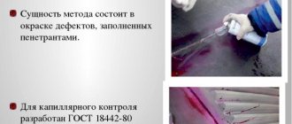
Quality control of welded joints of pipelines includes: a) operational control; b) external inspection and measurements; c) ultrasonic or radiographic control; d) metallographic studies of samples cut from control joints; d) steeloscopy (spectral analysis); f) hardness measurement; g) mechanical tests of samples cut from control joints; h) hydraulic or pneumatic tests.
Slide 40
(a) Operational control provides for: 1 - quality control and compliance of pipes and St. materials to the requirements of standards and technical specifications for production and delivery. 2 - checking the quality of preparation of pipe ends and pipeline parts for welding and the quality of assembly of joints. 3 – checking preheating t°. 4 - quality control and welding technology. 5 — checking the heat treatment modes of welded joints.
Slide 41
(b) Based on the result of external inspection and measurements, the seams must satisfy the following requirements: 1 - the shape and size of the seam must comply with GOST-16037. 2 - the surface of the weld must be finely scaly: porousness, fistulas, accumulations of pores, burns, sagging at the transition of the weld to the base metal of the pipe are not allowed. 3 - the transition from the directional metal to the main one should be smooth. Undercuts in transition sheets from the seam to the base metal are allowed no more than 10% of the pipe wall thickness, but no more than 0.5 mm. In this case, the total length of the undercut on one welded joint should not exceed 30% of the length of the seam.
Slide 42
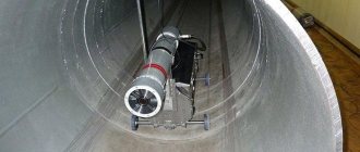
Inspection of the pipe from the inside
Slide 43
(c) Inspection of welded joints by radiographic or ultrasonic methods should be carried out after eliminating defects identified by external inspection and measurements. Welded joints of pipes are necessarily subjected to selective X-raying in the amount of 5-10% (first check) and 10-25% (second check) of the number of joints welded by each welder.
Slide 44
(d) Joints of pipelines of categories I and II for superheated steam and hot water are subject to mandatory metallographic control. Category I includes pipelines for superheated steam with a pressure above 4 MPa and a temperature above 350°C and hot water with a temperature above 184°C; Category II – pipelines of superheated steam with pressure up to 3.9 MPa and temperature up to 350°C and hot water with temperature from 80 to 184°C. For pipes made of carbon and low-alloy steels, one section is cut out for metallographic examination; for pipes made of austenitic steel, four sections are cut out.
Slide 45
(e) Welded joints of alloy steels are subject to steeloscopy for the presence of main alloying elements in the following cases: 1 - selectively, but not less than two joints made by one welder using one batch of welding materials. 2 - if after heat treatment the hardness of the welded joint does not meet the established requirements. The results of steeloscopy are considered satisfactory if the control confirms the content of the corresponding chemical elements in the deposited or base metal.
Slide 46
(f) Hardness measurements must be made on each heat-treated welded joint at the center of the weld in the heat-affected zone, along the base metal. Ultrasonic hardness tester MET-U1A The insertion force of the diamond pyramid is 9.8 N and is created by a calibrated spring. The relative change in the resonator frequency is converted by the electronic unit into the hardness value of the selected scale (HB, H V, H R) and displayed.
Slide 47
(g) Mechanical tests of samples cut from control joints in accordance with the requirements of GOST 6996-66 (tensile strength, relative linear elongation)
Slide 48
(h) Hydraulic tests are carried out with water at a temperature not exceeding 100° C. When testing for strength, the test pressure is maintained for up to 10 minutes, after which it should be reduced to working pressure. At operating pressure, a thorough inspection of the pipeline body is carried out, as well as a density (tightness) check. It is possible to replace the hydraulic test with a pneumatic one in winter and for large pipe diameters, and all safety measures must be observed.
Slide 49
For pneumatic testing, air or inert gas must be used. The pressure in the pipeline during pneumatic testing should be increased gradually with inspection of the pipeline when it reaches 0.6 test pressure - for a pipeline with a working pressure of up to 2 kgf/cm² - 0.3 and 0.6 test pressure - for pipelines with a working pressure above 2 kgf/cm². The results of all tests must be entered into the pipeline passport.
Slide 50
Welding of low-carbon steel pipelines at a temperature of -30°C can only be carried out with preheating of the joint and the adjacent zone 200-250 mm wide to a temperature of 150-200°C.
Slide 51
Local heating and heat treatment of the circumferential seams of pipelines during installation are carried out using a special device with a steel casing, which is protected from the inside with asbestos. The diameter of the casing is 180-220mm larger than the diameter of the pipe. The burner flame is directed tangentially to the pipe. Combustion products exit through a gap of 5-7 mm between the pipe and the edge of the casing.
Slide 52
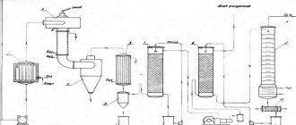
Devices for protection against precipitation
Slide 53
Independently 1. option Types of pipelines. Purpose of pipelines. Who is allowed to weld pipelines? How are pipelines assembled? In what cases are the remaining backing rings used? The procedure for welding rotary joints. Why is heat treatment of pipe joints performed? What electrodes are used for welding pipelines? What types of welding are used for welding pipelines? Methods for quality control of pipelines. Option 2: What is a pipeline? At what pressures do pipelines operate? Who controls the quality of pipeline welding? Assembly tolerances. In what cases are the remaining backing rings not used? The procedure for welding fixed joints. How is heat treatment of pipe joints carried out? How to boil the root of a seam? In what case is manual arc welding used when welding pipelines? How are pipelines hydraulically tested?
How deformations are eliminated in the technological process of producing welded structures
No matter how precise the welding, deformation of the product is inevitable. However, there are ways to combat it before and after welding.
Let's consider the process using the example of welding an I-beam. Deviations from its design geometry are:
- Reducing the length of the I-beam.
This happens in the process of making four seams connecting the walls and flanges of the beam. There are two ways to avoid reduction: provide for shrinkage and take a longer workpiece, or the leg of the weld must be reduced to the minimum values that can be set. - Warping of walls and shelves.
There are usually two reasons for the occurrence of misalignment: incorrect assembly or lack of rigid fastening of the position of the shelf relative to the wall on the opposite side of the weld. The shelf is most often secured by tacking braces, the material of which is selected separately, since a weak brace can be bent along with the shelf. - Mushroom shape of the welded beam flange.
This defect can be difficult to correct, but it will definitely arise, and it is impossible to protect against it. You can only achieve the minimum acceptable values of mushroom shape. There are several ways to prevent this defect. The first is to reduce the leg of the weld to the minimum permissible values and minimize the size of the gaps between parts before welding, since the most common reason is their increased dimensions.The second method is to prepare a shelf with a reverse bend, which is done with an edge bender; the bending angles are calculated using a special technique. Currently, this technology is not used due to lack of equipment. How to deal with fungiformity?
This can be done using thermal straightening, which, despite the highly labor-intensive process, remains the most affordable method. The process consists of heating the outer part of the shelf (opposite the axis of the wall) with a manual autogenous cutter. This is done with a thin wall. If the wall is thick, then heating occurs opposite the weld. The result of heating will be visible only after some time, so overheating is unacceptable. If it does occur, a reverse mushroom shape will appear and the structure will have to be reheated, but this time at the welding seam.
Another option for correcting mushroom shape is possible, but to use it you will need a special rolling machine; finding one is currently extremely difficult, since their production stopped with the collapse of the USSR.
- Saber-shaped or crescent-shaped I-beam.
This is perhaps the most common product defect among young manufacturers. The reason is a change in the sequence of actions during manufacturing. It must be done strictly in the order indicated in the figure.Sometimes, to minimize the number of turns, as well as fixing stretch marks, they resort to the “1-4” and “2-3” scheme. However, the likelihood of saber-like appearance increases significantly. To prevent it from appearing, it is necessary to weld from the center to the edge back in a stepwise manner. This option sometimes helps to avoid a defect. However, the main method of fighting still remains the use of a special press for mechanical straightening of sickle and saber shapes. If there is no access to such equipment, then you will have to use thermal straightening. Heating is always performed from the side opposite to the defect. The result is a correction.
Saber-shaped deformation of an I-beam occurs when transverse stiffeners or parts of gussets are welded along the side surface, to the holes of which parts of the beam structure are attached.
It is impossible to avoid curvature, but preventive measures should be taken to minimize:
- When semi-automatic welding of a structure, the joining of the stiffeners is partially done before connecting the wall and the shelves. Before the main welding, a seam is made under the rib, and then the shelves and the wall are connected longitudinally.
- If the shelves and walls are welded first, then the stiffeners are attached at minimum temperatures and the least permissible seam lengths. The best option may be to weld the ribs alternately on each side of the I-beam so that they compensate for each other's deformations. But only if such a process is constructively possible.