The meaning of the word "shell"
OBECHAYKA
, -and,
gen.
pl. - seagulls,
dat.
- seagulls,
w.
Specialist. and
region
Side wall of various cylindrical or conical vessels, drums, pipes.
|| The side figuredly curved part of the body of musical instruments, which serves to connect two soundboards. Guitar shell.
Violin shell. Source (printed version):
Dictionary of the Russian language: In 4 volumes / RAS, Institute of Linguistics.
research; Ed. A. P. Evgenieva. — 4th ed., erased. - M.: Rus. language; Polygraph resources, 1999; (electronic version):
Fundamental electronic library
- Shell - an open cylindrical or conical structural element (such as a rim or drum, ring, short pipe), used in the manufacture of welded or wooden vessels, musical instrument resonators, hatch walls, etc.
The shell of the drum is called the cadl. The shells of musical instruments are made from thin planks or three-layer plywood by bending, accompanied by heating in a moistened state.
Metal shells for boilers, tanks, reservoirs and other metal structures are produced by rolling for small sheet thicknesses or by bending and rolling for sheet thicknesses of more than 40 mm.
May also refer to an accessory that strengthens the walls of a corrugated cardboard package.
OBECHA'YKA
, and,
w.
and
OBE'CHKA
, and,
w.
(region). The rim of a sieve, sieve, basket, etc.
Source:
“Explanatory Dictionary of the Russian Language” edited by D. N. Ushakov (1935-1940);
(electronic version):
Fundamental electronic library
shell
1. special side part of the body of musical instruments (violin, cello, viola, guitar, drum, etc.) ◆ Drum - any projectile consisting of a covered shell
or peeling an empty box; casing around the wheel and machine swings... Grigory Fuks, “Two in a Drum”, 2003 // “Zvezda” (quote from NKRYA)
2. tech. conical or cylindrical drum without bottoms made of sheet material; blank for boilers, tanks, etc.
Making the Word Map better together
Hello!
My name is Lampobot, I am a computer program that helps you make Word Maps. I can count perfectly, but I still don’t understand very well how your world works. Help me figure it out! Thank you!
I began to understand the world of emotions a little better.
Question: power plant
- is it something neutral, positive or negative?
Source
Basic Concepts
The shell is a cylindrical or conical pipe of relatively short length. You can think of it as a small rim on a drum or an ordinary ring. Only the technical dimensions of these products may vary depending on the purpose of the design.
The cross-section of the shell can be not only conical, but also oval. Similar products are used in many industries:
- metallurgy;
- oil refining;
- construction;
- mechanical engineering.
The latter sector uses shells especially actively to obtain the following elements:
- pipes, boilers, tanks and containers;
- steel bands, as blanks for flanges, crane drums, etc.;
- bridge supports, water pipelines, sewer crossings;
- chimneys, flues;
- bends, tees, etc.
Structural elements of solid propellant rocket motor
3.1. Solid propellant housings
The main power element of a solid propellant rocket engine is its body. The body is made by casting, stamping, turning, as well as using welding and winding. The materials for the body are low-carbon, easily welded steel; cold-rolled steels with a strictly directional arrangement of fibers; aluminum, magnesium, titanium alloys; fiberglass.
From the point of view of design and strength calculations, the engine housing shell is considered as a thin axisymmetric shell. Housing shells can be classified: according to the material used - metal and non-metal; in shape, Fig. 3.1., - into cylindrical, spherical and conical, and non-metallic shells can have the shape of a “half-cocoon” or “cocoon”; according to the presence of welds (metal shells) - into welded (with circular, spiral and longitudinal seams) and seamless (rolled and seamless). The shells can be smooth, have local elements glued, soldered or welded to them. The shells can end with flanges or transitions into the bottoms. Finally, the shells can be single or multi-sectional, and have intermediate stiffening belts (rings, bandages, clamps).
Manufacturing of shells
Metal shells are made of sheet steel, markings are chosen according to customer requirements. Sheets are selected depending on the required thickness, and the materials are inspected for corrosion. Next, they proceed directly to cutting, shaping, and welding work is performed.
Manufacturing stages:
- preparation of project documentation;
- marking patterns according to the required sizes;
- cutting of blanks;
- rolling on sheet bending machines;
- welding work;
- assessment of pipe strength;
- checking the tightness of the weld.
The use of modern equipment and the high qualifications of our employees allows us to control the manufacturing process at all stages. After assessing the quality, the finished shells are sent to the warehouse, the batch is shipped or delivered to the client.
Shell - what is it? Short description
From Masterweb
Many names go back to ancient times. In special texts the word “shell” is often used. What it is? This is a structure in the form of a ring or a short pipe, cylindrical or conical, with a constant or variable cross-section. The shell is used as a component of more complex structures. The material can be very diverse - from high-alloy unique alloys and composite materials to concrete and wood.
Stator inner shell
The inner shell of the stator consists of shell elements in the form of sectors of a circle, connected in series around the circumference. The shell elements form an assembly with the outer crankcase by means of a single shell element attachment point at a first end of the shell element and a single support node at a second end opposite the first. The shell element contains a tenon fixed to the shell element and included in the groove of the attached flange fixed to the crankcase. The tenon has an end protruding in the axial direction of the shell relative to the adjacent part of the tenon. The invention makes it possible to ensure reliable fastening of the shell elements to the crankcase, as well as to reduce the influence of thermal effects on the shape of the internal shell of the stator. 10 salary f-ly, 6 ill.
The claimed invention relates to the inner shell of a stator. Control of thermal expansion is becoming fundamental in the field of turbojet engines in order to ensure good efficiency by adjusting the clearances between the stator and the tips of the moving blades of the engine. The stator design that is often found is double and consists of a crankcase surrounding an inner shell in contact with the gas that creates the thrust of the machine. Usually the outer casing is made as one piece so that it has good mechanical resistance and can be cooled by ventilation, with good regularity, which is facilitated by its continuity, while the shell is made of a composite, formed by a sequence of rings made up of elements in the form circular sectors. Thanks to this arrangement, the stresses that would otherwise arise in the shell due to installation in a more rigid crankcase and contact with a stream of hot gas remain moderate, and the different rings can be blown at different intensities to independently regulate their diameter. The prior art includes a number of double stators, which are disclosed in French patents 2683851 and 2695164 issued to the Applicant.
Figure 1 represents one of these concepts, where the outer crankcase is indicated by 1, the shell elements by 2 and the rotor by 3; shell elements 2 are assembled from adjacent elements located on adjacent rings, using assemblies consisting of a tenon 5 on one of the elements 2 and a groove 6, into which the tenon 5 fits, on another element 2. Fastening units 7, better represented in Fig. .2, combine the elements 2 of the shell and the crankcase 1. They mainly include a bolt 8 inserted through the boss 9 of the crankcase 1 and a flange 10, made in the form of a support collar, of the crankcase 1, located at the end of the flange 11, made in the form of a rib of the shell. The bolts 8 are located, as a rule, obliquely in order to ensure axial and radial fixation of the guide vanes (shell elements 2). Elastic circular gaskets are located behind the rings of the shell elements 2 and include a head 13, sandwiched between a flange 10 made in the form of a support collar and a shoulder 14 of the crankcase 1, as well as a sealing edge 15, the end of which rests on a flat sealing surface behind the shell elements 2. Thus, individual chambers 17 are isolated between the crankcase 1 and each of the rings of the shell elements 2.
The goal of obtaining good adjustment of the diameters of the shell rings is not fully achieved because changes in diameter and waviness of the rings easily appear.
In this case, these disadvantages arise due to the attachment points 7, which manifest themselves as irregularities in the structure in the shell elements 2. More precisely, the inventors have come to the conclusion that the presence of multiple fastening units 7 is harmful, and propose to use only one unit per shell element 2.
Since the only fastening unit does not allow the shell element 2 to be satisfactorily held with its help alone, it is also envisaged to use the only support unit on the shell element 2 instead of the rejected fastening units. This support unit includes a tenon fixed to the shell element and included in the groove of the attached flange, which is fixed to the crankcase. The shell elements have the ability to move slightly in the axial and circumferential directions of the machine in the support unit due to the possibility of sliding of the tenons in the grooves, without fear of excessive movements, so how is it possible to achieve a state of support. As a result, it was possible to combine proper fastening of the shell elements to the crankcase and soft installation, which prevents their irregular deformation.
Other characteristics and advantages of the invention will now be described with reference to the following drawings, in which:
Fig.1 - composite stator,
Fig.2 - place of fastening of the shell element to the crankcase,
Fig.3-6 preferred embodiments of the invention: Fig.3 - first preferred embodiment; Fig.4 - shell element according to this embodiment; and FIGS. 5 and 6 show basic details of two other preferred embodiments.
Numerous elements from the prior art, already mentioned in connection with the presentation of FIGS. 1 and 2, are found in the invention. In particular, we are talking about the design of the fastening units 7 and the presence of connection elements 4 between the shell rings and elastic gaskets 12 to dampen vibrations. Each shell element 2 is combined with only one fastening unit 7, which is located near the first end 20 (close to the axial edge of the shell element 2). The support unit 21 is also located on each shell element 2 symmetrically relative to the fastening unit 7, near the same end and close to the opposite second end 22. Fig. 3 clearly shows the advantage that the shell elements 2 are arranged in a staggered pattern, i.e. their ends 20 or 22 are a continuation of the middle lines of the shell elements 2 of the adjacent rings. By adopting this arrangement, a shell of a coherent structure is obtained, despite the small number of fastening nodes 7 and support nodes 21 of these elements. This can be explained by noting that each shell element (for example, the element designated as 20) is surrounded by two elements belonging to adjacent rings, and the fastening points of which (designated as 70) are located approximately in the middle of the length of the element 20. These fastening points 70 also limit the radial deformation of the element 20 due to the connections of the tenon 5 and groove 6 between the rings of the shell elements 2. This advantage becomes even more obvious if the fastening nodes 7 and the support nodes 21 are located at the ends of the shell elements 2, which is an advantage since they are designed to interact with one another different, since the attachment points 70 of the adjacent elements are located exactly half the length of the element 20, in the place where it was least supported without them.
If the structure is sufficiently rigid in the radial direction, then, on the contrary, in the axial and circumferential directions it has good compliance due to the possibility of sliding in the support units 21, which allow movement within certain limits in the above-mentioned directions. Consequently, it was possible to find a compromise between the need to allow the shell to deform due to thermal effects, while maintaining a circular shape with a slightly varying diameter.
FIG. 4 shows that the support assembly 21 includes a tenon 23 located at the end of an elbow 24 that extends above the shell element 2. This tenon 23 is formed on the lower surface of the groove 25 secured to the crankcase 1. According to this preferred embodiment, when the fastening unit 7 and the support unit 21 are close to the ends 20 and 22 of the shell members 2, they abut the ends of the adjacent shell members 2 in such a way that that the groove 25 can in this case be made in the flange 11, in the form of a rib, a fastening point for the adjacent shell element 2. The tenon 23 extends in a circumferential direction relative to the machine, protruding from the shell element 2 to which it belongs above the next element. It will be seen that other configurations are possible, but in all cases the support units 21 allow moderate mutual axial and circumferential movements of adjacent shell elements 2.
Here, as in other preferred embodiments, the fastening units 7 are designed with two parallel bolts 8, which does not change anything in the uniqueness of the fastening unit 7, since these bolts 8 are located side by side. A pair of bolts 8 makes it possible to obtain a more reliable fastening and, in some cases, to eliminate bending moments arising from the influence of aerodynamic forces on the elements 2 of the shell: if the resulting F of these forces or its projection in the radial direction passes between the bolts 8, then its action is expressed by the product of the aerodynamic forces, in this case, the shell elements 2 themselves will not be subject to noticeable bending.
In the embodiment shown in figure 5, the tenon of the fastening unit has a more complex shape and is designated by position 26; it fits into the groove 27, made between the installation locations of the bolts 8, and, therefore, after the elbow 24, respectively, has a part 28 made in the form of a plate, which fits under the flange 10, made in the form of a support collar, fastening unit 7, and a more massive end , more precisely, wider, protruding in the axial direction and placed between two parts of the flange 10, made in the form of a support collar, in the groove 27, which is made in the flange 11, in the form of a rib. Here, the main part of the tenon 26 has an axial extension rather than a tangential one, which does not change anything in terms of support.
In other preferred embodiments, the flanges in which the grooves are made do not belong to the fastening units 7, but to separate parts. This is represented in Fig. 6, where the fastening units 7, which here contain only one bolt 8 but remain located near the first ends 20, no longer have grooves 25 or 27: a flange 30 consisting of a cover 31 connected to the crankcase 1 the fastening means 32, in the form of a bolt, similar and parallel to the bolt 8, and with a recess for the groove 33, is located in the vicinity of the fastening unit 7 in such a way that the flange 10, in the form of a support shoulder, hangs over the end of the lining 31 and closes the groove 33. the assembly 21 of the shell element 2 also includes a tenon 34 with an end 35 protruding axially above the groove 33 to obtain the desired connection. The end 35 is connected to the main body of the shell element 2 adjacent to that which carries the attachment unit 7 by means of an elbow part 36 adjacent to the second end 22 of the shell element 2 and directed radially.
In these various preferred embodiments, it is noted that the support units 21 and the fastening units 7 belonging to the shell elements 2 located sequentially on the same circumference interact with each other, i.e. that the fastening units 7 provide at least one abutment or support surface for the tenon of the support unit 21: in the embodiment according to Fig. 4, the tenon 23 rests radially on the surface of the groove 25 and abuts tangentially against the flange 10, in the form of a support collar, or flange 11, in the form of a rib, fastening unit 7; in the embodiment according to Fig.5, the tenon 26 abuts tangentially against the flange 10, made in the form of a support collar, which surrounds it, and rests radially on the surface of the groove 27; and in the embodiment according to Fig. 6, the end 35 of the tenon abuts tangentially against the flange 10, in the form of a support collar, and the lining 31 and rests radially on the bottom of the groove 33. This interaction of the fastening nodes 7 and the supporting nodes 21 simplifies the design, allowing you not to resort to the use flanges of complex shape to ensure the sliding of the tenons of the support units, while limiting it.
The proximity of the location of the fastening nodes 7 and the support nodes 21 of the adjacent shell elements 2 allows, if necessary, to hold the support node 21 in the desired position in the radial direction, without the use of any additional part, as in the case shown in Fig. 4, where the tenon 23 of the support node 21 radially rests on the surface of the groove 25 adjacent to the fastening node 7, made in the adjacent shell element 2.
1. Internal stator shell, consisting of shell elements (2) in the form of sectors of a circle, connected along the circumference in series and forming an assembly with the outer crankcase (1) by means of a single fastening unit on the shell element at the first end of the shell element and one support unit (21) on the shell element at the second end (22) opposite the first end (20) of the shell element (2), wherein said shell element contains a tenon (23, 26, 34) fixed to the shell element and included in the groove (25, 27, 33 ) an attached flange, which is fixed to the crankcase, characterized in that in the shell elements the tenon has an end (29, 35) protruding in the axial direction of the shell in relation to the adjacent part (28, 36) of the tenon.
2. The shell according to claim 1, characterized in that flanges (10, 11) are formed for each of the tenons in the attachment points of one shell element adjacent to the shell element carrying the tenon (23, 26, 34).
3. Shell according to claim 1, characterized in that the flanges (30, 37) are autonomous and assembled with the outer crankcase using fastening means (32).
4. The shell according to claim 3, characterized in that the fastening units (7) are located in such a way as to close one end of the grooves (33).
5. The shell according to claim 3, characterized in that the fastening units have a pair of parallel bolts (8) for fastening between the outer crankcase and the shell element, and the grooves (27) are located between the bolts (8) of the pair.
6. The shell according to any one of claims 3-5, characterized in that the fastening unit is installed on each element of the shell in such a way that the resulting force (F) of the aerodynamic forces acting on the above-mentioned element passes between the bolts of the fastening unit.
7. The shell according to any one of claims 1-6, characterized in that the shell elements of one ring are assembled with the shell elements of the next ring in a checkerboard pattern.
8. The shell according to claim 2, characterized in that part (28) of the stud is adjacent to the end (29) of the stator shell in the assembled state under the flange (10) of the mounting unit (7) of the adjacent shell element.
9. The shell according to claim 2, characterized in that the spike contains, after the elbow (24) connected to the shell element, a part (28) made in the form of a plate, which is included in the assembled state of the stator shell under the flange (10) of the unit (7) fastening the adjacent shell element.
10. The shell according to claim 9, characterized in that the tenon contains, after the part (28) made in the form of a plate, the end (29) is wider than the part (28), which protrudes in the axial direction and is configured to be inserted in the assembled the state of the stator shell between the two parts of the flange (10) in the groove (27).
11. Shell according to claim 3, characterized in that part (36) of the tenon is adjacent to the end (35) of the tenon and protrudes in the radial direction.
Household use
People began using shells in prehistoric times. That is, they included the side part of any cylindrical or conical dish, for example, a birch bark piece rolled from a piece of birch bark. When the production of tin buckets and basins was subsequently mastered, their side wall also served as a shell.
And outside of the dishes, what is the shell? This is primarily part of the resonator body of a wide variety of musical instruments - strings and percussion. A balalaika, a guitar, a double bass, and a drum have a shell. By the way, the shell of a drum is called a cadl.
With the development of casting technologies, sewer manholes acquired cast iron shells - this is the base of the manhole attached to a pipe or vessel, on which its cover is laid. Recently, both covers and shells of hatches began to be made of composite materials.
Another example of a shell is the well-known concrete ring from which well pipes are assembled.
shell
Encyclopedic Dictionary . 2009.
See what a “shell” is in other dictionaries:
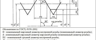
shell - A sheet metal blank in the form of a hollow cylinder or truncated cone [Terminological dictionary of construction in 12 languages (VNIIIS Gosstroy USSR)] shell A cylindrical shell of a closed profile, open at the ends. [PB 03 576 03]… … Technical Translator's Directory
SHELL - (Top rim, brim) rim around the upper edge of the mars. Samoilov K.I. Marine dictionary. M. L.: State Naval Publishing House of the NKVMF of the Union SSR, 1941 Shell open at the ends cylindrical or conical drum made of sheet material, ... ... Marine Dictionary
shell - drum, blank Dictionary of Russian synonyms. shell noun, number of synonyms: 5 • drum (34) • ... Dictionary of synonyms
BACK - in music, the side part of the body of musical instruments, usually stringed ones, with an upper and lower soundboard. The shells of the drums are called cadles... Big Encyclopedic Dictionary
SHELL - WHEEL, shells, female. and OBECHKA, shells, female. (region). The rim of a sieve, sieve, basket, etc. Ushakov's explanatory dictionary. D.N. Ushakov. 1935 1940 ... Ushakov's Explanatory Dictionary
SHELL - WHEEL, shells, female. and OBECHKA, shells, female. (region). The rim of a sieve, sieve, basket, etc. Ushakov's explanatory dictionary. D.N. Ushakov. 1935 1940 ... Ushakov's Explanatory Dictionary
OBECHAYKA - female sidewall east shingle rim, twisted splint, sides of a sieve, sieve, basket, drum; a wide, flat hoop on a box, etc. Save the shell from the sieve, so you can put the chicken on the eggs. A sieve with a shell and a broom with a gang (dowry).... ... Dahl's Explanatory Dictionary
Shell - 30. Shell is a cylindrical shell of a vessel with a closed profile, open at the ends. Source: NP 044 03: Rules for design and safety ... Dictionary-reference book of terms of normative and technical documentation
Shell - Blanks for drum shells Shell ... Wikipedia
shell - a bast rim on a sieve, sieve, millstone, dial. shell, bechaika, Sevsk. (Conversion), Ukrainian character, blr. person. Usually explained from *obvitachayka from *ob and *vit; see vit. The form on e must in this case contain a level of alternation with the form on and ... Etymological Dictionary of the Russian Language by Max Vasmer
Source of the article: https://dic.academic.ru/dic.nsf/es/40173/%D0%BE%D0%B1%D0%B5%D1%87%D0%B0%D0%B9%D0%BA% D0%B0
Industrial shell: what is it?
The side part of any cylindrical or conical vessel also represents one or a combination of several shells. When manufacturing nuclear or chemical reactor vessels, according to the requirements of designers, it is necessary to manufacture vessels that are under high pressure and in aggressive environments. Moreover, the length of such a vessel far exceeds the capabilities of foundries and machining machines.
There is a way out - the body is broken into parts. The side walls of the reactor are divided into several (up to ten) rings - cylindrical shells, each of which is sized to be cast and processed separately using existing equipment. After mechanical processing, which brings the dimensions of the body elements to the specified ones, they are connected together on welding stands several tens of meters long. The cover and bottom of the reactor vessel are also divided into segments, which are welded together and, at the last stage, welded to an assembly of several shells, thus achieving the integrity of the vessel.
For vessels of smaller sizes and lower pressure, a different method of making shells is used - they are not cast, but bent from steel sheets on rollers and welded or riveted along the longitudinal seam.
Where are shell pipes used?
Shells are durable pipes that can withstand high loads, therefore they are used in construction, as components in the manufacture of various equipment and laying general-purpose pipelines. Due to the presence of a welding seam, they are not used in lines with pressure drops or intended for aggressive environments.
Scope of application of shells:
- on hydraulic structures as capacitive equipment or connecting elements of water supply systems;
- when installing heating networks for transporting hot or cold water;
- as protective covers for various lines in production or during outdoor installation;
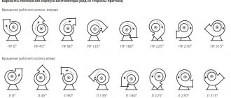
- for installation of ventilation, the diameter is selected according to the size and purpose of the system;
- as a basis for the manufacture of production drums, boilers and various vessels.
Dimensions are selected according to the purpose and features of use. Typically, such information is indicated in the technical documentation and agreed upon when placing an order. We will produce shells with any wall thickness, required length and required pipe diameter.
Defense industry
And what is a military shell? Shells are also widely used in aviation, shipbuilding and the production of ground-based military equipment. Wherever there are hatches - on ships, submarines, airplanes, spacecraft and tanks - they must be attached to something.
In addition to their load-bearing function, shells are also used for fastening locking devices, weapon systems and other equipment. The shells are also the bases of the rotating towers, which house artillery or missile weapons or electronic warfare equipment.
We hope that now you know exactly what it is - a shell. And the new term will no longer confuse you.
Shell - what is it? Short description
Many names go back to ancient times. In special texts the word “shell” is often used. What it is? This is a structure in the form of a ring or a short pipe, cylindrical or conical, with a constant or variable cross-section. The shell is used as a component of more complex structures. The material can be very diverse - from high-alloy unique alloys and composite materials to concrete and wood.
Household use
People began using shells in prehistoric times. That is, they included the side part of any cylindrical or conical dish, for example, a birch bark piece rolled from a piece of birch bark. When the production of tin buckets and basins was subsequently mastered, their side wall also served as a shell.
And outside of the dishes, what is the shell? This is primarily part of the resonator body of a wide variety of musical instruments - strings and percussion. A balalaika, a guitar, a double bass, and a drum have a shell. By the way, the shell of a drum is called a cadl.
With the development of casting technologies, sewer manholes acquired cast iron shells - this is the base of the manhole attached to a pipe or vessel, on which its cover is laid. Recently, both covers and shells of hatches began to be made of composite materials.
Another example of a shell is the well-known concrete ring from which well pipes are assembled.
Industrial shell: what is it?
The side part of any cylindrical or conical vessel also represents one or a combination of several shells. When manufacturing nuclear or chemical reactor vessels, according to the requirements of designers, it is necessary to manufacture vessels that are under high pressure and in aggressive environments. Moreover, the length of such a vessel far exceeds the capabilities of foundries and machining machines.
There is a way out - the body is broken into parts. The side walls of the reactor are divided into several (up to ten) rings - cylindrical shells, each of which is sized to be cast and processed separately using existing equipment. After mechanical processing, which brings the dimensions of the body elements to the specified ones, they are connected together on welding stands several tens of meters long. The cover and bottom of the reactor vessel are also divided into segments, which are welded together and, at the last stage, welded to an assembly of several shells, thus achieving the integrity of the vessel.
For vessels of smaller sizes and lower pressure, a different method of making shells is used - they are not cast, but bent from steel sheets on rollers and welded or riveted along the longitudinal seam.
Technical characteristics of shells
The sizes of metal shells range from 10 to 4200 mm in diameter. The thickness of the cylindrical and conical wall can be from 2mm to 100mm. The width of the products can be any, depending on customer requirements. If the cylindrical shell is made from a standard solid sheet, then its width does not exceed 3000 mm, and if made from special rolled stock - up to 6000 mm. Shells are also produced from blanks welded from several parts; in this case, the number of seams will be more than one, and the diameter can exceed 4200 mm.
Welding of the shell is carried out according to the drawing or technical specifications of the customer. Department 13 guarantees high reliability of the connection of metal sheets and the tightness of the seam. Well-weldable steels are used for production:
- carbon - 17G1S, St3, St-20, 13HFA, 09G2S;
- boiler rooms - 20K, 17G1s, 09G2S;
- heat-resistant - 10Х17Н13М2;
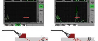
Other grades of steel are also used for the manufacture of shells, depending on the specific requirements for the product. Often the project specifies grades according to the AISI standard: 304, 316, 321. After cutting, shaping and processing on a sheet bending machine, the workpiece is welded and checked by ultrasonic and radiographic methods. The conical shell is also checked for compliance with the wall angles. The product is formed by cold bending. If steel that is not resistant to bending is used, then the hot bending method is used.
The finished shells are processed at the ends, the seams are cleaned, and upon the client’s request, holes are drilled for fittings, hatches and other technological elements. The price of the finished shell depends on the steel grade, size and degree of additional processing.
Defense industry
And what is a military shell? Shells are also widely used in aviation, shipbuilding and the production of ground-based military equipment. Wherever there are hatches - on ships, submarines, airplanes, spacecraft and tanks - they must be attached to something.
In addition to their load-bearing function, shells are also used for fastening locking devices, weapon systems and other equipment. The shells are also the bases of the rotating towers, which house artillery or missile weapons or electronic warfare equipment.
We hope that now you know exactly what it is - a shell. And the new term will no longer confuse you.
Source