Scope of application of heating main trays
what heating main trays look like
No more than 200 trays are produced for a batch with a height of 400-800 mm and 100 pieces with a height of 1000 mm.
Trays are accepted based on test results, during which the following properties are taken into account:
- Resistance and strength of concrete when exposed to low temperatures.
- Waterproof properties of the material.
- Compliance of reinforcement connections and their quantity in the places specified in the product documentation.
- Quality and reliability of welding in frame construction.
- Compliance with the tray sizes described in the documentation.
- The thickness of the concrete block from the base to the frame.
- The number of microcracks formed during shrinkage of the structure.
Water resistance should be checked for at least two products from a batch.
- Tests to check the dimensions of the structure, the protective concrete layer and the presence of a high-quality arrangement of reinforcement connections inside it are carried out using a single-stage selective control prescribed in GOST 13015-75 and ionizing radiation.
- The thickness of the concrete wall is measured at at least five perimeter points at the end points of the product, and non-perpendicularity is measured by the gap distance between the square and the plane of the end of the tray.
- The strength of concrete under compression load is checked according to GOST 10180-78.
- When assessing the quality of the homogeneity of the material and its strength characteristics, GOST 10180-78 is used.
- If the concrete strength indicators do not meet after control tests, the product is sent for revision until the required parameters are achieved or is rejected.
- The resistance of concrete to frost is determined according to GOST 10060-76, and its waterproof properties according to GOST 12730.5-78.
To protect underground communications, reinforced concrete trays are widely used. The structures reliably isolate pipes and cables from external damage from natural, man-made, biological and physical sources.
What are the trays made of?
They are made from special grades of concrete that can withstand various temperature conditions, are resistant to erosion and are highly waterproof. High-strength steel a-1, b-3 or vr-1 is used for the frame, which reliably adheres to the concrete structure from the inside.
The process of manufacturing heating main trays (Video)
L7-8 method of immediate stripping
Types of trays.
Trays vary in size, shape, purpose and installation. The length of the finished product does not exceed 4 m. Depending on the length, they are divided into:
- Additional 0.42-0.72 m.
- Standard 0.72-1.5 m.
- Channels 1.5-1.8 m.
- Tunnels 1.8-4 m.
Their height is no more than 1.68 meters.
Trays are used for pipelines in groundwater, in turbulent underground springs, loose rocks and seismically hazardous areas. The strength and reliability of the protective structure is made at a high level, and the requirements for its manufacture are specified in the regulatory collections GOST 13015-2003 series 3.006.1-2.87 “Prefabricated reinforced concrete channels and tunnels from tray elements” and TU 5859-001-86780364-2008, According to them, the following requirements are imposed on the tray manufacturing technology:
- The compressive strength of concrete is not lower than 22.5V.
- The water permeability properties of the structure must be higher than W4.
- The material must be resistant to cold for more than 200 cycles of temperature difference.
- Concrete is strengthened by a frame made of reinforcement, which is made of steel with classes A-I, A-III or BP-I;
Marking.
All symbols in the design marking contain the values of its characteristics and parameters:
- The first letter indicates the name of the structure and the type of its length (L-tray, d-extension, a - mortgage).
- The following numbers show its load / per 1 m2.
- Designation /2 is for non-standard or short trays.
The markings display the following information:
- Manufacturer of the tray.
- Design brand.
- Date and time of release of finished products.
- Strength characteristics of the material.
- Dimensions and weight of the product.
- Technological control mark.
Floor slabs intended for installing trays have similar markings; they are half as long as them, and therefore do not have a length marking. It is worth paying attention to the features of some small slabs that are resistant to load in only one direction.
The reinforcement in their frame is located in different places, depending on its value in the product range. This point must be taken into account when installing and calculating pressure, because An uneven load on the slab will lead to its destruction.
Table of sizes of heating main trays (L, LC)
Series 3.006.1-2/82:
| Marking | Leg thickness | Width | Height | ||
| external | internal | external | internal | ||
| L-4 | 50 | 780 | 620 | 530 | 450 |
| L-5 | 50 | 780 | 600 | 680 | 600 |
| L-6 | 50 | 1160 | 1000 | 530 | 450 |
| L-7 | 50 | 1160 | 980 | 680 | 600 |
| L-11 | 60 | 1480 | 1280 | 700 | 600 |
| L-12 | 60 | 1480 | 1240 | 1010 | 900 |
| L-14 | 60 | 1840 | 1600 | 570 | 450 |
| L-15 | 70 | 1840 | 1600 | 720 | 600 |
| L-16 | 70 | 1840 | 1580 | 1030 | 900 |
| L-20 | 80 | 2160 | 1880 | 1040 | 900 |
| L-23 | 80 | 2460 | 2180 | 740 | 600 |
When determining the internal dimensions of LK series 3.006.1-8 trays, its internal width is taken into account, before the start of rounding. This is due to the design feature of this series, which has a rounding inside the lower part of the product.
| Marking | Leg thickness | Width | Height | ||
| external | internal | external | internal | ||
| LK-300-90-45 | 50 | 880 | 620 | 430 | 350 |
| LK-300-90-60 | 50 | 880 | 600 | 580 | 490 |
| LK-300-90-90 | 60 | 880 | 560 | 880 | 780 |
| LK-300-120-60 | 60 | 1180 | 780 | 580 | 480 |
| LK-300-120-90 | 60 | 1180 | 760 | 880 | 780 |
| LK-300-120-120 | 60 | 1180 | 720 | 1180 | 1060 |
| LK-300-150-60 | 70 | 1480 | 1060 | 580 | 480 |
| LK-300-150-90 | 70 | 1480 | 1040 | 880 | 760 |
| LK-300-150-120 | 70 | 1480 | 1000 | 1180 | 1060 |
| LK-300-180-60 | 80 | 1780 | 1340 | 580 | 460 |
| LK-300-180-90 | 80 | 1780 | 1320 | 880 | 760 |
| LK-300-180-120 | 80 | 1780 | 1280 | 1180 | 1040 |
| LK-300-210-90 | 80 | 2080 | 1620 | 880 | 740 |
| LK-300-210-120 | 80 | 2080 | 1580 | 1180 | 1040 |
| LK-300-240-120 | 80 | 2380 | 1880 | 1180 | 1020 |
Corner trays.
Corner trays are used for joining parts in vulnerable areas of the pipeline, at bends, intersections and turns of pipes. Their main difference from other parts is the presence of a cutout with the same width on its side. It fixes and securely fastens all segments of the structure.
Such products have parameters identical to conventional trays, retain thermal insulation in the pipeline and protect it from groundwater and physical damage. Their marking begins with the designation “LU”, and the letter “n” in the name indicates that there is a mirror cutout in the tray.
When installing a corner tray, it is necessary to fill its joints evenly to prevent distortion in the structure.
Cable tray sizes
Metal cable trays are produced in several standard sizes. This applies to the height of the side, and the length and width of the structure.
The height of the side varies from 30 to 200 mm, the length of the tray is from 2 to 3 m, the width of the base is from 50 to 800 mm, and the steel thickness is 0.7 - 2 mm. The choice of trays is made based on what you need to get in a particular situation. If you need to buy a cable tray of a certain standard size, then you need to buy your own set of accessories for it, and in each situation it is different, although it necessarily includes connectors and corner elements.
Floor slabs.
Floor slabs are fixed to the top of the tray and prevent water and soil from entering it from underground sources, insulating the pipeline structure from the effects of natural processes on it. A small gap is made between the pipes and the walls of the tray to ventilate the space and create thermal insulation.
Slab making process
Such structural elements are made of reinforced concrete; a reinforcing mesh is inserted inside large slabs, bonding the concrete base and increasing its strength. Small lids use separate rods that work in a similar way. It is necessary that the water resistance of all parts coincide and meet the operating requirements.
Volume.
Trays have different volumes, its value depending on the size of the entire structure; the largest capacity is possessed by channels and tunnels, and the smallest trays have an additional structure. The volume of various models can be found out by their markings from a special table in collections of standards and regulations, such as GOST and TU.
| product name | Length, mm | Width, mm | Height, mm | volume, m3 |
| L-4-8 | 5970 | 780 | 530 | 0,72 |
| L-4-8/2 | 2970 | 780 | 530 | 0,36 |
| L-4d-8 | 720 | 780 | 530 | 0,09 |
| L-5 | 2970 | 1080 | 680 | 0,51 |
| L-5-8 | 5970 | 780 | 680 | 0,88 |
| L-5-8/2 | 2970 | 780 | 680 | 0,44 |
| L-5d-8 | 720 | 780 | 680 | 0,11 |
| L-7 | 2970 | 1400 | 680 | 0,7 |
| L-7-8 | 5970 | 1160 | 680 | 1,06 |
| L-7-8/2 | 2970 | 1160 | 680 | 0,53 |
| L-7d-8 | 720 | 1160 | 680 | 0,14 |
| L-11-8 | 5970 | 1480 | 700 | 1,44 |
| L-11-8/2 | 2970 | 1480 | 700 | 0,72 |
| L-11d-8 | 720 | 1480 | 700 | 0,18 |
Installation technology.
Installation of elements is carried out in the following stages:
- 1) Digging channels for laying heating mains.
- 2) Installation of trays in the dug channel and securing pipes in them.
- 3) The pipeline is isolated from ground and underground waters.
- 4) The trays are closed with a lid, laying and securing the slabs on them.
- 5) Insulating the joints of the slabs of the entire structure.
- 6) Burying a trench for the utility network.
The immersion depth of channels and tunnels varies greatly in different sections of the pipeline, especially under important engineering structures:
- The pipeline running along highways is laid below the road surface at a depth of 0.5-6 m.
- The depth under the railway is 1-4 m; in such areas it is necessary to use very strong trays that can withstand a weight of 15 tons/m2.
- in the absence of roads, the minimum depth for the pipeline is 0.5-6 m.
- Communications located in workshops are immersed to a depth of no more than 0.3 meters, protruding above the ground no more than 200-400mm
When laying utility networks, it is important to consider what kind of soil lies in a given place; if the groundwater level is located high, then use loose sandy rocks as support.
Loose soil to support the pipeline structure must be at least 10 centimeters thick and have a slope angle of 0.002 mm for drainage.
How well the trays are installed can be determined by the microcracks in them; the permissible error in case of soil subsidence is no higher than 0.1 mm.
The thickness of the earth layer above the structure is carried out in accordance with the requirements of GOST, and the measurement error can be no more than 5 mm.
Waterproofing protection.
Underground communications and pipelines are protected from water ingress by insulating structural elements using waterproof materials. The requirements for waterproofing utility networks are set out in SNiP 41-02-2003 “Heat networks”.
In the absence of groundwater in sections of the heating main, the joints of the trays are treated with water-repellent agents or wrapped with molten bitumen, creating a waterproof layer.
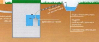
If the groundwater level is high, drainage and pumping of water are used or waterproof materials are used that exceed the height of the groundwater level by 0.5 m. It is necessary to carefully inspect the waterproofing areas and, if poor quality work is detected, correct it, because Upon completion of the work, access to the pipeline and its structural elements will be difficult due to the layer of soil and the accumulation of protective structures.
There are three types of pipeline insulation:
- 1) Anti-pressure. Protection of the structure from high groundwater pressure.
- 2) Anticapillary. Means of protection against moisture that rises through capillaries in porous soils.
- 3) Non-pressure. Protective measures against accumulated moisture in waterproof soil layers.
The following methods are used to insulate heating mains:
- Wrapping the structure with highly water-resistant materials.
- Use of chemical water-repellent lubricants.
- Applying concrete materials to the pipeline, paving it with bituminous hardening masses, which seal the pipe and prevent water from entering.
- The trays are foamed and painted with special sealing substances.
- Clogging of concrete joints, clay materials with high fat content.
- The tray structures are insulated with metal sheets, secured by welding or dowels.
Before starting work, it is necessary to divert groundwater from sealing areas or carry out drainage work. If there are quicksand, it is recommended to use protective barriers before excavating the soil.
To protect the dug channels from flooding by precipitation, drainage grooves and storm drains are installed inside them.
Before insulation, the walls of structures are prepared as follows:
- Plastering tray joints and leveling their surface.
- Cleaning isolated areas from debris.
- Drying or moistening and applying viscous substances to structures.
Prices for reinforced concrete trays.
The cost of trays varies and depends on the quality of the material, the place of production of the product, its characteristics and size.
Cable laying trays come in the following types:
- solid,
- perforated,
- wire,
- staircases
Solid trays are suitable for rooms with high humidity. Perforated metal trays are lightweight, which greatly simplifies installation. They are used for laying cable routes to organize electrical systems in residential, office and commercial premises. The wire cable tray is laid in horizontal and vertical directions indoors. The ladder tray has a high load-bearing capacity and is used for installing power cables in workshops, administrative buildings, and residential buildings. Operated in open space.
Reinforced concrete profiles for heating mains.
An underground pipeline is very often exposed to various types of hydrogeological, chemical and biological conditions, which leads to corrosion and wear of the pipes.
To prevent this from happening, measures are being developed to protect such structures. The pipes are covered with covers made of resistant material that protect them from the penetration of natural reagents. One such device is reinforced concrete trays.
Tray design.
The trays are made from the most stable grades of concrete, have a U-shaped structure, and are reinforced inside with steel reinforcement to give the structure high strength.
Such devices are put on pipes, welded and cemented all the fragments, creating a monolithic and sealed structure.
how to store heating main trays
Protective properties.
- The trays play the role of drainage channels, preventing groundwater from entering the pipes.
- Create thermal insulation properties that retain heat in the pipeline.
- Protects against alkaline and chemical reagents.
- Prevents physical wear and damage to pipes, as well as damage to pipes by rodents.
The use of trays will extend the life of the pipeline for many years.
Installation of channels is done in several ways:
- The slabs lie on the channel structure, leaning on it (Cl).
- The covers of the trays are located at the bottom of the channel, and a concrete structure (CLp) is mounted on top of them.
- The trays are connected together and secured with metal profiles. The free space inside them can accommodate a person with a height of up to 180 cm (CLs).
For the strength of the structure, a sand cushion is created, the tray lying on it is securely fixed in the ditch.
Installation of trays involves moving and turning them over, which can be easily done using self-made hooks from bent reinforcement rods. They are fixed in holes on the sides.
Special viscous mixtures are used to seal the gaps and joints of the structure; in flooded areas with quicksand, a plastic bitumen mass is used to isolate them from them. To avoid distortions in the structure, both sides of the channels are evenly sprinkled with earth.
Advantages of using reinforced concrete trays for heating mains.
- 1) They can withstand heavy loads while maintaining structural strength.
- 2) No installation difficulties and economical cost of the product.
- 3) Installation of trays can be carried out in hard-to-reach places, near groundwater and in seismically active areas.
- 4) High water resistance of the material of the trays.
Specifications.
The quality, dimensions and properties of the material are carried out in accordance with the requirements of GOST 13015.0-83. Based on its points, you can find out that for the manufacture of trays they use a material that is resistant to temperature changes and groundwater pressure on it. The most suitable structure for such conditions is concrete reinforced from the inside with iron reinforcement.
Requirements for concrete grades.
- The grade of concrete for making trays is not lower than M300.
- Strength indicators must withstand compression of the structure by at least 70%.
- For fillers, use particles no larger than 15 mm in size.
- The use of active additives in the solution is prohibited.
Special requirements are placed on the quality and thickness of steel for reinforcement.
Installation of metal cable trays
Although each manufacturer includes instructions with the product, there are certain rules that apply to all types of iron trays. In particular, when choosing an installation method, the type of cable for which the tray itself is installed, the height of its installation, the type of fasteners used, and the features of the building are taken into account.
Additionally, although electrical wiring trays are almost always made of metal, different alloys can be used to make them. For example, not everyone has corrosion protection in the form of a zinc coating, but it is necessary to ensure the strength of the entire structure as a whole.
Table of slabs and trays for heating mains.
| Trays for heating mains (heating networks), floor slabs for heating mains Series 3.006.1-2.87 | ||||
| Name | Dimensions (LxWxH, mm) | volume, m3 | Weight, t | Price for 1 unit. with VAT, rub. |
| L4-8 | 2970x780x530 | 0,37 | 0,9 | 5620 |
| L4d-8 | 720x780x530 | 0,09 | 0,23 | 1600 |
| L5-8 | 2970x780x680 | 0,46 | 1,13 | 6890 |
| L5d-8 | 720x780x680 | 0,11 | 0,28 | 2100 |
| L6-8 | 2970x1160x530 | 0,46 | 1,13 | 6890 |
| L6d-8 | 720x1160x530 | 0,11 | 0,28 | 2100 |
| L7-8 | 2970x1160x680 | 0,56 | 1,35 | 8300 |
| L7d-8 | 720x1160x680 | 0,14 | 0,35 | 2500 |
| L8d-8 | 720x1160x1000 | 0,2 | 0,5 | 3500 |
| L9d-8 | 720x1160x1310 | 0,26 | 0,65 | 4490 |
| L10d-8 | 720x1480x550 | 0,17 | 0,43 | 2970 |
| L11-8 | 2970x1480x700 | 0,72 | 1,8 | 11300 |
| L11d-8 | 720x1480x700 | 0,18 | 0,45 | 3100 |
| L12d-8 | 720x1480x1010 | 0,24 | 0,6 | 4120 |
| L13d-8 | 720x1480x1320 | 0,32 | 08 | 5410 |
| L14-8 | 2970x1840x570 | 0,93 | 2,29 | 14850 |
| L14d-8 | 720x1840x570 | 0,23 | 0,58 | 3500 |
| L15-8 | 2970x1840x720 | 0,99 | 2,45 | 15600 |
| L15d-8 | 720x1840x720 | 0,25 | 0,63 | 4300 |
| P5-8 | 2990x780x70 | 0,16 | 0,4 | 2170 |
| P5d-8 | 740x780x70 | 0,04 | 0,1 | 750 |
| P6-15 | 2990x780x120 | 0,28 | 0,7 | 3600 |
| P6d-15 | 740x780x120 | 0,07 | 0,17 | 1200 |
| P7-5 | 2990x1160x70 | 0,24 | 0,6 | 3650 |
| P7d-5 | 740x1160x70 | 0,06 | 0,15 | 1010 |
| P8-8 | 2990x1160x100 | 0,34 | 0,86 | 5250 |
| P8d-8 | 740x1160x100 | 0,09 | 0,21 | 1450 |
| P11-8 | 2990x1480x100 | 0,44 | 1,1 | 6250 |
| P11d-8 | 740x1480x100 | 0,11 | 0,27 | 1720 |
| P15-8 | 2990x1840x120 | 0,66 | 1,63 | 8750 |
| P15d-8 | 740x1840x120 | 0,16 | 0,41 | 2500 |
All structures and buildings have pipelines and various communications. These networks form systems to meet human needs. These include electricity, sewerage, water supply and other amenities. Communication networks include all elements of pipelines, reinforced concrete lots and floor slabs that deliver a certain resource to the consumer’s home.
Due to difficult conditions, underground pipelines are additionally protected with trays and floor slabs.
Construction of communications is carried out in accordance with SNiPAM. The channel technology method is often used in the equipment of pipelines and in the future, their high-quality operation. Reinforced concrete trays are evenly installed in the dug trenches, pipes are secured inside them and the entire structure is isolated from groundwater.
After installing the pipes, the trays are covered with protective covers and once again reinforced with insulating materials. The trays reliably protect the heating main from sources of rust, oxidation and physical damage. For the strength and uniformity of the structure, a sand structure is created, which is its base.
The main function of reinforced concrete trays is to maintain thermal insulation in the pipes and isolate them from groundwater sources. During their production, much attention is paid to careful alignment and marking of product parts. All joints are inspected and properly sealed, checked for gaps, and waterproofing lubricants are applied.
Waterproofing is usually carried out at the installation stage of the structure, but some manufacturers pre-provide waterproof properties to the product, which extend the life of the pipeline and protect it from rust caused by the interaction of groundwater with pipes.
In the manufacture of trays, heavy and high-quality grades of concrete are used, and a reinforced steel frame is installed inside the block, which can withstand high and constant loads.
Trays are a popular product in modern times, in populated areas and cities, along with the construction of new residential areas, there is an urgent need for laying new pipelines, as well as updating and replacing existing ones. Their main advantages are expressed in economical cost and durability of the structure. The products are practical to use, easy to install and assemble, and installation of the entire structure does not take much time.
Load on heating main elements.
When calculating the amount of load that a pipeline structure can withstand, pay attention to:
- Quality reinforcement, in a concrete block frame.
- The brand of concrete from which the trays are made.
- The amount of pressure on a structure exerted by weight and dynamic loads.
Having calculated the parameters, a tray model is selected, depending on the strength of the reinforcing mesh, its location, the diameter of the rods and the load-bearing characteristics.
There are two types of load on heating mains:
- Constant. The total mass of residential buildings and other buildings, engineering structures, and highways.
- Short-term. Load on the structure of people and vehicles
The sum of the totality of these loads determines the immersion depth of the structure.
Tray and slab selection options.
Models of trays designed for vertical loads on pipeline elements are divided into series and the most commonly used and popular are 3.006.1-2/82 and 3.006.1-8.
Products with series 3.006.1-2/82 are intended for laying heating mains under the base of highways and next to them.
The depth under the route is 0.5-6 meters, the width of the channel is 0.3-6 meters.
The vertical load should be calculated on an area of 8-15 tf/m2. The amount of load that a selected element can withstand can be seen in its marking, then compared with the value in the strength table of the actual load-bearing capacity.
how to choose heating main trays
When choosing a tray, you should carefully study its characteristics and have complete information about the pipeline, namely:
- Thickness and characteristics of the insulating layer, as well as its type.
- Cross-sectional diameter of the pipes used.
- Where in the pipeline are thermal chambers and support structures installed?
- Where are the stabilizers located at vulnerable points of the heating main, which have different structural structures?
When calculating the load, they rely on information about the height, width and cross-section, from which they calculate the volume required to lay pipes inside the tray for their free passage.
The calculations take into account the gap between the elements, their lower part and the surface under the pipeline, and to determine the load, data on the volume of already filled pipes is used, taking into account large and multiple reserves. For areas with highways, the axial and base load from freight transport, as well as the mass of the soil, are additionally determined.
Channel slabs marked VP are used in the construction of individual parts of bridges and their spans. The design of such slabs is very durable and can withstand the constant flow of freight and passenger vehicles.
The reinforcement used inside can withstand tensile loads; such features make the structure very stable; such trays are recommended for installing pipelines under highways.
For laying pipelines in areas without roads or other heavy loads, less durable tray designs are used and covers of the 3.006.1-2/82 series are used to cover them.
When it is time to replace or repair pipes:
- Using excavators, trenches with tray structures are excavated.
- Floor slabs are removed.
- Necessary sections of the pipeline that are unsuitable are replaced with new ones or repaired.
- At the end of the work, the covers are closed again, the trenches are buried, and the trays continue to protect the pipeline from harmful influences.
When constructing a pipeline, trays marked L4-8 and L7-8 are most often used, and floor slabs marked P5-8 and P8-8 are used as covers.
Reconstruction and repair of heating mains
The marking on the tray provides the following information about it:
- The letter at the beginning of the marking indicates the type of tray.
- The first number indicates its size.
- The last figure after the hyphen indicates the maximum load on the tray tf/m2
The floor slab markings have the same designations. The load values for slabs and trays do not coincide in most cases, therefore each pipeline element is selected separately for the load of the slabs, and separately for the load of the trays.
The use of reinforced concrete trays in the pipeline structure will protect it from natural conditions and extend its operation for many years.
Drainage trays
They are used in the installation of drainage systems and other communication lines. Depending on the loading method, products are: rain; drainage Such structures are used for water drainage in residential areas, as well as in industrial areas.
The advantages of such designs include:
- half a century of reliable service;
- resistance to high loads and deformations;
- resistance to a wide temperature range;
- use of safe materials in production;
- resistance to rust formation.
Installation of heating main trays.
Correct assembly and installation of trays affects the further use of the pipeline and its durability, and also provides protection from mechanical stress and isolation from underground processes associated with groundwater, quicksand and soil erosion. Such phenomena destroy the unprotected pipeline and expose its metal pipes to rapid rusting.
Video: installing trays
The installation process of structural elements is carried out in 4 stages:
1) Work on digging canals. Using special equipment, a trench of the required depth and length is created in the ground, then the excess earth is moved to another place or a prepared mixture of gravel and sand is used for backfilling at the final stage of construction.
2) Preparatory work. The trench section is compacted and backfilled with gravel, grooves are created to drain storm water and the surface is leveled. The structural parts of the trays are processed to improve their waterproof properties.
3) Installation. The trays are installed, they are covered with earth, leveled and a slight slope is created to avoid possible distortions of the structure. The pipeline is placed inside the trays, its joints are welded and further structural tests are carried out.
4) Insulation work. The pipeline is wrapped in thermal insulation material, and the trays are covered with lids.
The influence of trays on the speed of pipeline installation.
Many factors influence the speed of assembly and installation of a pipeline, these include the skill of engineers and workers, the power of equipment, the quality of protective structures and the pipeline itself.
Most problems in the operation of heating mains arise from the use of trays whose protective properties do not meet the requirements for the selected area. The influence of the environment on the structure nullifies all the work done. It is necessary to use trays suitable for the given area, carefully seal their joints and check the integrity of the structure.
Installation of reinforced concrete trays
During installation, the trays are placed on a pre-prepared cushion; it can be made of sand or other similar material. To install the trays, you need special equipment - a crane or others, as well as at least three people. All work must be carried out by qualified workers, strictly in accordance with safety precautions.
After laying the trays is completed, the joints are sealed. After which the resulting channel from the trays is carefully finished with insulating materials (laid with flooring materials, or treated with special mixtures). Reliable waterproofing protects the trays from moisture, which significantly extends their service life.
Advantages of cable management trays
When choosing trays for wires, you need to remember the advantages of metal products - strength and ability to withstand heavy loads. The designs also have other advantages:
- Easy to install. Does not require expensive tools. They are assembled using connecting elements or special connections.
- Wide range of sizes. Allows you to select elements that suit the client's requirements. Length - 2 - 3 meters.
- Reliability. Hanging cable trays have a curved top edge and a rounded turn shape, so the chances of damaging the insulating layer of the wire are minimized.
- Presence of holes. They allow cables to be routed along the entire length of the route.
- Resistance to external factors. The metal “channel” does not deform as a result of sudden temperature changes.
- The metal cable tray provides additional protection from shock, vibration and weather conditions.
- The price of a metal cable box with a lid depends on its type and type, but in general remains affordable.
If you have a choice of where to buy cable trays, choose a reliable one that has taken a leading position in the Russian market since 2007. Reasonable price and European quality are what distinguishes the company’s products from other organizations.