01/12/2017 master
Nowadays, the most common type of lighting is LED. Thanks to the huge number of advantages, such light sources have taken their place in almost any area of human activity.
LEDs
Without them it is no longer possible to imagine electronic equipment, modern toys and many other attributes of modern society. LED strips are especially often used as lighting devices today. Therefore, it is very important to know how to solder diodes with your own hands in order to independently repair failed radio-electric parts at home or replace them correctly.
We remember the school physics course
In order to solder LEDs (for example, SMD type), you need to know what some of the signs on the circuits mean. Namely:
- "U". This letter on all electrical diagrams indicates voltage. It is measured in V (volts);
- "I". Under this designation lies the current. It is measured in A (amps);
- "R". This letter means the electrical resistance of the circuit elements. This indicator is measured in Ohms (ohms).
All of the above values reflect Ohm's law, which is described by the following formula:
In addition, you need to understand that under the letter “P” is power, which is measured in W (watts). Power is determined by the following formula:
The decoding of these values must be known in order to correctly solder LEDs into any circuits and boards.
Let's remember the school physics course
In order to solder circuits that include LEDs, you will need a soldering iron.
First you need to prepare a tester, soldering iron and calculator. You should remember this simple thing: you cannot direct the beam coming from the LED into a person’s eyes. And now it’s time to remember a little physics:
- the letter “U” on electrical diagrams indicates voltage, measured in volts (V);
- current is designated by the letter “I”, measured in amperes (A);
- the electrical resistance of parts and conductors is designated by the symbol “R” and measured in ohms (Ohm);
- all this data is included in the formula characterizing Ohm’s law: U = R * I;
- the letter “P” denotes power, measured in watts (W);
- power can be calculated using the formula: P = U * I.
How are diodes connected?
Before you start soldering LEDs (for example, SMD type), you need to know how they are connected to the circuit or in series to each other (if we are talking about LED strips).
Note! LEDs are most often connected to a network with a voltage of 12 or 9 V. But usually the devices are designed for a current consumption level of 0.02 A (20 mA).
Current stabilizer
The ideal option for LEDs is to connect them through a current stabilizer. It should be remembered that such stabilizers will cost slightly more than single LEDs (for example, SMD type). This must be taken into account when independently assembling radioelectric devices.
In order to power yellow and red LEDs, a voltage of 2.0 V is often required. At the same time, to power blue, green and white LEDs - 3.0 V. The following example will help to understand this issue:
- a 12 V battery is available, as well as 0.02 A and 2.0 V LEDs;
- the simplest solution here would be to supply a voltage of 2.0 V to each diode;
- in this case, the extra 10 V will need to be extinguished using a resistor. It is also often called resistance;
- Using Ohm's law, we calculate the resistance value (R = U/I). As a result, we get R = 10.0/0.02 = 500 Ohm;
- Also, in order to protect the resistance from excess heat, it is necessary to calculate its power. The result will be P = 10.0 * 0.02 A = 0.2 W.
For greater reliability, it is necessary to take a resistance of slightly larger capacity. Note! As the resistance power increases, its overall dimensions will naturally increase. Knowing the above aspects, you will be able to connect the LEDs to the battery correctly using a resistor for this. The main thing here is to strictly observe the polarity of the parts used.
What is needed for work
Many radio electronics enthusiasts who practice self-assembly of various devices are interested in the possibility of independently soldering LEDs (for example, SMD type) for circuits. If you have the proper tools and knowledge, creating such circuits yourself is quite possible. For this type of work you will need:
- tester;
- calculator;
- medical tweezers (optional, but recommended);
- soldering iron
Tester
Note! When working with LEDs, especially when testing them, you need to be careful not to direct the beam coming from these elements into your eyes.
As you can see, the set of tools here is small and can easily be found in any home. With this kit, you will be able to correctly solder diodes, both in the circuit and in series as part of the LED strip.
The structure of diode elements and how to solder them
A standard LED is a glass bulb with an approximate diameter of 5 mm, to which lead legs are attached.
Diode appearance
The short leg represents the negative terminal, and the long leg represents the positive terminal. If you mix them up when soldering, the LED will not light up. The process of soldering such elements has the following algorithm:
- We place each diode in its own place;
- soldering areas should be treated with ordinary tin or flux;
- after that, apply a soldering iron to them for a couple of seconds;
- After this, the remaining legs can simply be bitten off.
After you have soldered all the LEDs to the circuit, you need to check your handiwork. To do this, they must be connected to power. If all the diodes light up, this means that you did everything correctly. In addition, there are LEDs, which, for ease of working with them, are produced in the form of special strips. They can be cut and connected to each other, which makes it possible to use them for lighting rooms, shop windows, etc.
Places for cutting LED strips and soldering wires
Such tape should only be cut in appropriate places. If you cut in another place, you will simply ruin the product by damaging the LED connection. Such pieces need to be soldered using special contact pads that end these sections.
Note! You can solder LED strips using a soldering iron with a power of 40 V.
As a flux, you should use a special solution that looks like a gel. Remember that the ends of the wires in this situation should be well tinned. You can also use special devices to create contacts between pieces of LED strip - connectors. But they are quite expensive, so they are rarely used.
Soldering Features
After we have refreshed our school knowledge and the basics of connecting LED elements, and also found all the necessary tools, we can begin to directly work with the parts. LEDs can be connected in series. The important thing here is to know how to do it correctly.
Note! In order to solder diodes in series, they should be selected with the same parameters.
The resulting chains of LEDs can be used in a wide variety of devices and purposes. Most often, they are used to organize various types of lighting (open or closed) for premises, as well as vehicles. When installing such chains, you should remember that the voltage in the car's electrical network will be higher than 12 V (14-14.5 V). The machine's power supply is not characterized by constant voltage. To suppress possible interference, special voltage stabilizers are needed.
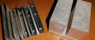
Chip KREN8A
Independent assembly of voltage stabilizers is possible on the basis of KREN8A and K142EN8A microcircuits for a 9 V network. KREN8B and K142EN8B microcircuits are suitable for a 12 V network. A small-sized soldering iron is suitable for soldering this element. Its tip should heat up to 260 degrees.
Note! The duration of the soldering process for each point should be 3-5 seconds.
To ensure that the soldering itself went correctly, you need to know the following rules and recommendations:
- If you don’t have even minimal soldering experience, you need to practice first. Otherwise, there is a high risk that the LEDs will not work or will even deteriorate. To improve your skills, you should use wires with different cross-sections;
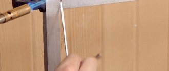
- It is imperative to use standard tin-lead solder and flux for aluminum;
Flux for aluminum
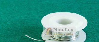
- Wires that have not been covered with oxides must be tinned immediately after exposure. To do this, you need to take a small amount of solder and heat it on the soldering iron tip. Then we touch the rosin with it and run it along the exposed sections of the wires. As a result of such manipulations, the solder will spread into a thin film;
- sometimes tinning is not allowed. Then the wire should be placed on an aspirin tablet and heated with a soldering iron. Heating lasts 3-5 seconds.
LED soldering process
Knowing these rules, you can correctly solder the LEDs in series.
How to solder LEDs?
To solder LEDs you will need aluminum flux.
In this way, you can connect several diodes in series. In this case, it is recommended to select LEDs with the same parameters. Strings of LEDs of different colors can be installed and connected to a wide variety of systems. It's easier to do this on a motor vehicle. You just need to remember that the voltage in the car network is usually not 12, but 14-14.5 V. In addition, it is not always constant; there is also a lot of interference. To suppress interference, it is necessary to use voltage stabilizers. They can be assembled on the basis of K142EN8A, KREN8A microcircuits for a 9 V network. For 12 V, K142EN8B and KREN8B are suitable.
For soldering, a small soldering iron is suitable, the tip of which can heat up to 260 degrees. The soldering process should not exceed 3-5 seconds per point. Medical tweezers will be of great help. To ensure fast and high-quality soldering, you need to use a special flux for aluminum, ordinary tin-lead solder.
If you have no experience with soldering, you should learn a little about this matter. For trial exercises, wires of different sections are suitable. The insulation is removed from the ends of the wires. Fresh wires are usually not covered with oxides; they can be tinned immediately. To do this, take a small amount of solder onto the tip of a heated soldering iron, touch the rosin and move the tip along the exposed parts of the wires. The solder spreads over the wire in a thin film.
If for some reason tinning is difficult, you need to put the wire on an aspirin tablet and heat it for 3-5 seconds with a soldering iron. After this procedure, even a wire with traces of obvious oxidation is perfectly coated with tin. It is useful to practice until the wires can be tinned efficiently and quickly. After this, you need to learn how to tin the stranded ends, which most often have to be unraveled to remove traces of oxidation from them, then moistened with an aspirin tablet.
Now soldering the LEDs should be easy and quick.
Another soldering option
In addition to conventional LEDs, there are chips that are mounted in LED strips. The most common LEDs today are SMD type.
SMD LED
This circuit element is a leadless component. SMD does not have traditional copper lead wires. Therefore, such elements are connected using printed circuit board tracks. Soldering is also used to connect the SMD diode to the board. It is necessary to solder track tracks and contact pads to them. Soldering such a circuit component is not difficult, since for this you can use a low-power type of soldering iron with a capacity of 10-12 W. Therefore, you can quite conveniently and quickly solder each contact in series separately.
Soldering SMD components
There are situations when it is necessary to desolder SMD components to replace or test them. In such a situation, in order to prevent the element from overheating, you need to warm up all its terminals at the same time. If such a need with SMD components happens often, then it makes sense to purchase a special set of soldering iron tips. These stings should have two or three small branched ends. They are very easy to work with SMD as the risk of damage is minimized even when they are glued to the PCB. Sometimes it is impossible to use a low-power soldering iron. Then, in order not to damage the element during soldering, a copper wire with a diameter of one millimeter should be wound to the tip of a powerful soldering iron.
Wire wound around tip
Such a homemade attachment will be quite easy to use with a powerful soldering iron when working with SMD LEDs.
Soldering SMD LEDs
SMD LEDs are leadless devices that are soldered with special pads.
SMD LEDs are leadless devices. They do not have traditional solder feet. They are soldered with special contact pads located on the device body. This can be done with a low-power soldering iron 10-12 W. It is best to have a special tip for this work, which has a branch at the end. Another way out is to wind a copper wire with a diameter of 1 mm onto a standard tip. The ends of the wire will act as a branch.
If necessary, this attachment can be removed from the tip to be used again later. The ends of the wound wire are brought together and separated depending on the size of the LED.