Screw pumps are positive displacement pumps. There are other names for these pumps: screw, gerotor, worm and eccentric pumps.
Screw pumps are a type of rotary-gear pumps and are conventionally divided into single-screw and multi-screw. A multi-screw pump is one in which the main drive screw (rotor) is helically meshed with one or more driven screws. When the drive screw rotates, the driven screws also begin to rotate. Multiscrew pumps have a higher efficiency and the ability to create higher outlet pressure. In this article we will look at the operating principle and design of pumps that are most often used in industrial production - single-screw pumps.
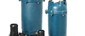
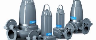
Single-screw pumps can be divided into high-performance pumps for pumping large volumes of product and screw pumps for barrels, Eurocubes and other mobile containers. The main difference between these two types is their purpose. The former have a massive structure and are designed to pump a large volume of liquid without immersing any of its parts in the container. The latter, on the contrary, have in their design a submersible part of such a diameter that can be installed in the filler hole of the barrel. However, these pumps have a similar design, are self-priming and are capable of pumping viscous liquids.
Let's consider the design and operating principle of a screw pump. Any screw pump can be divided into two parts. The first part drives the working body of the pump, thereby causing the pump to pump liquid. It includes a motor and gearbox. The second is the mechanical part of the pump, thanks to which the liquid is pumped with a certain performance and pressure.
Pump motor and gearbox
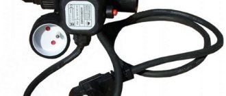
Closed-type asynchronous electric motors are most often used to drive a screw pump. The electric motor power can reach 15-20 kW, and the shaft rotation speed varies from 300 to 1500 rpm. Many manufacturers of screw pumps can offer a pump with an electric motor, which is equipped with a frequency converter. If the frequency converter is of a standard type, then it is usually mounted on the vertical part of the trolley, on which the screw pump itself is located. This is done for those cases when it is necessary to pump liquid from different containers with one pump. In the case when there is no need to move the pump, it is installed permanently and in this case frequency converters with a wireless control unit are used.
As a rule, all screw pumps are equipped with reduction gears in their design. The gearbox is the connecting link between the engine and the mechanical part. It serves to change the number of revolutions coming from the electric motor to the pump itself. A reduction gear reduces the number of revolutions and increases torque. Sometimes there are gearboxes that can change the direction of rotation of the electric motor shaft. The amount of torque is very important when the pumped liquid has high viscosity and density. Structurally, the gearbox consists of several gear wheels that are in sequential engagement with each other, despite the fact that the diameter of the wheel on the electric motor side is always smaller than the diameter of the wheel on the pump side. That is why the output gearbox always has more torque and lower angular velocity. Together, the electric motor and gearbox are called a gearmotor.
The most important characteristic in this case is the gear ratio. It shows how many times the torque has increased and how many times the speed transmitted by the electric motor has decreased. Manufacturers of screw pumps offer geared motors with different gear ratios that are suitable for almost any task. When selecting a gear motor, you should adhere to the following rule: the higher the viscosity and density of the pumped product, the higher the gear ratio should be, because in this case there will be a high torque and a lower angular speed of the pump working body. The pump will be able to draw viscous liquid from the container into the working chamber without overloading the electric motor. Here, the power of the electric motor itself is also no less important, because the liquid still needs to be supplied over a distance. However, the required pump pressure is determined not only by the power of the electric motor, but also by the design features of the mechanical part.
In addition to electric motors, screw pumps are equipped with pneumatic motors powered by compressed air. They are usually found on vertical drum pumps and are similar in design to the air motors of centrifugal drum pumps.
Types and main technical characteristics
Among screw pumps, there are two categories. The fundamental parameter of this separation is the working depth at which these hydraulic machines are capable of operating. So, depending on this characteristic, they distinguish:
- standard screw pumps;
- deep category devices.
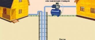
A screw pump, belonging to the standard category, is used for pumping water from wells or boreholes whose depth does not exceed 20–25 meters. Such pumps are often used to service wells with low flow rates, drilled in sandy aquifers (sand wells). Since using a screw pump it is possible to pump out a liquid medium with different capacities, while maintaining a stable pressure of the created flow and not paying attention to the content of sand inclusions in the water, this equipment is optimally suited for servicing wells of this type.
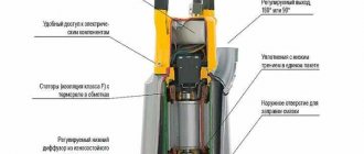
Monoblock screw pump with top-mounted water intake
The deep-grade screw well pump is equipped with an extended auger, which determines the impressive technical capabilities of such a hydraulic machine. Possessing high power and reliability, it can successfully service artesian wells, the water in which is located at a depth of up to one hundred meters. Of course, the price of such models is significantly higher than the cost of devices of the standard category, but in many cases, when it is necessary to ensure water supply from wells of considerable depth, such equipment simply cannot be done without.
Let's look at the technical characteristics of a well screw pump belonging to models in the mid-price category:
- productivity, showing how much liquid medium the pump is capable of pumping per unit time, is 1500–2000 l/hour;
- the pressure of the created liquid flow is 40–60 meters of water column;
- the temperature that the pumped liquid medium may have is from +5 to +40°C;
- the size of particles of insoluble solid inclusions that may be contained in the pumped water is 2–2.5 mm;
- The power of the electric motor driving the rotor and auger is 1–1.5 kW.
Sprut range of screw pumps
Most models of mid-price screw pumps, which are often used to equip household autonomous water supply systems, can operate from a 220 V electrical network.
Screw pumps for industrial use have more impressive technical characteristics. In particular, such devices, without compromising their technical condition, can successfully pump liquid media whose temperature significantly exceeds the above values. In addition, industrial screw-type pumps are able to work with liquid media containing insoluble solid inclusions, the particle size of which exceeds 2–2.5 mm.
Borehole screw pump for artesian water intakes
The main part of the body parts of screw-type well pumps is made of stainless steel, individual elements are made of durable plastic. To seal the internal structural elements of such hydraulic machines, gaskets made of rubber and silicone are used.
Since the moving elements of the internal structure of screw pumps are constantly in contact with the pumped liquid medium, they do not require additional cooling.
Mechanical part
The main components of the mechanical part of a screw pump can be considered the rotor (1), stator (2), pump housing (3), bearing housing (4), mechanical seal (5) and universal joint (6). All these parts are connected in series to each other and are located inside special supports (7).
The driveshaft, also called the “thrust”, has hinges at both ends. One hinge, through the adapter shaft, connects the “rod” to the gear motor, the second hinge to the pump rotor. The cardan shaft is the connecting link for transmitting torque from the engine to the rotor. In addition, since the cardan shaft has a hinged connection, torque can be transmitted at an angle relative to the axis of the electric motor shaft. To prevent the hinge mechanism from coming into contact with the pumped liquid during pump operation, they are placed in special sealed casings made of the same material as the “rod”.
The driveshaft is located inside a cylinder, which is the pump housing. The housing is connected by flanges, on the one hand, to the pump stator, and on the other hand to the bearing housing.
On top of the pump body there is a pressure pipe, which can have a threaded or flanged connection. Since screw pumps can pump liquid reversely, this pipe may well not be a supply pipe, but a suction pipe. In addition, the pump nozzle comes in the form of a loading funnel.
Loading funnels (or hopper) are used when the pumped product has a high viscosity, is pasty, and does not have flow properties. In these cases, the cardan shaft is replaced with an auxiliary transport (feed) auger, which also has a swivel joint. In addition to transmitting torque, the auxiliary screw moves the product loaded into the funnel to the gerotor pair.
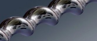
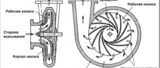
The gerotor pair is the most important component of a screw pump, which consists of a moving part - the rotor and a stationary part - the stator. The stator is a steel sleeve in the inner part, which has a spiral-shaped uniform elastomer layer obtained as a result of the vulcanization process. The metal of the stator housing and the inner elastomer layer are inseparably connected to each other. Depending on the purpose of the gerotor pair, the stator can be made of various materials. In a screw pump, the stator is sometimes called a cage and sleeve, and the rotor is called a screw, auger, or worm. The rotor is a screw that rotates inside the stator.
The rotor is a single piece, but it can be roughly divided into two parts. The first part is the head for attaching the rotor to the cardan shaft. The second is the rotor body itself, which has the shape of a spiral and is in constant contact with the holder during pump operation. The stator and rotor are a friction pair with internal cycloidal engagement. The gerotor pair of the screw pump is attached with flanges to the pump body. At the end, depending on the direction of rotation of the rotor, it has a suction or supply pipe.
To seal the pump drive, the design provides a mechanical seal. It is located between the “rod” hinge and the bearing housing.
The bearing housing is a unit consisting of two angular contact bearings and an adapter shaft, which, on the one hand, is connected to the gear motor using a key or splines, and on the other hand, it is pivotally connected to the driveshaft.
A horizontal screw pump can be designed with a bypass. This modification of the pump is used when a flow control device (for example, a solenoid valve) is additionally installed in the pressure line. The bypass allows you to avoid switching off the pump motor every time the valve in the supply line closes. When the valve is closed, the pump continues to operate and pumps liquid in a circle from the pressure pipe back to the suction pipe, thereby avoiding excess pressure in the area from the pump to the valve.
What to consider when choosing a pump
The choice of a specific model must be made taking into account its design features and characteristics, the parameters of the well (well) and the manufacturing company.
Pumps for wells or wells can be surface and submersible. The surface one is capable of operating at a depth of up to 10 m. The engine of this equipment is not protected from moisture and therefore requires installation under a roof. A submersible screw pump is much more powerful, has higher efficiency and allows water to be supplied from depths of tens and even hundreds of meters. Submersible models are sealed and remain below the water level during operation. They can function autonomously for a long time. The disadvantage of submersible products compared to surface ones is the difficulty of maintenance.
The main characteristics that are taken into account when selecting a model are: productivity, head height and lifting depth. The pressure in the water supply system and fluid flow depend on these characteristics.
Productivity is determined by the volume of liquid supplied to the discharge pipeline per second. It should provide peak consumption with a 10% margin. When calculating consumption, it is necessary to fully take into account all possible directions of consumption and their changes depending on the time of year and other conditions. If productivity is calculated based on average daily consumption, as is often suggested, rather than on peak consumption, then its value may be lower than necessary.
The pressure is measured in meters. To determine the required pressure, you need to add the height of the building and the depth of the source. Add 6 m and multiply the result by the pressure loss coefficient in the pipeline, which is 1.15. If the source is far from the house, it is necessary to add one additional meter of pressure for every 10 m of horizontal pipeline. The vertical distance is taken into account in a 1:1 ratio.
When calculating the required equipment characteristics, it is necessary to include a 10% margin. If the well depth is 90 m, then it is recommended to choose a product with a maximum depth of 100 m.
Important well parameters include diameter (the maximum diameter of the pump depends on it), production depth, and flow rate. These indicators are indicated in the well passport, which is issued by the organization that carried out the drilling. Or you can measure them yourself. It is almost impossible to accurately measure debit. It depends on the measurement technology, climatic conditions, time of year and conditions of use of the well.
The service life of the pump is affected by the quality of the build and the material from which it is made. This is usually stainless steel, occasionally aluminum, which is less durable.
Pump operating principle
The pump is connected to an electrical circuit or pneumatic line. When the pump is turned on, the electric motor shaft begins to rotate at a certain number of revolutions per minute. The rotation of the electric motor shaft is transmitted through a coupling connection to the gearbox shaft. The gear wheels of the gearbox, which are in sequential engagement, reduce the number of revolutions at the output of the gearbox and increase the torque. Through the adapter shaft located in the bearing assembly, the angular speed of the gear motor is transmitted to the cardan shaft or transport auger, which in turn drives the pump rotor through a swivel joint.
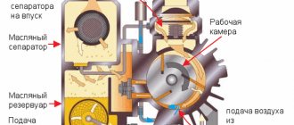
Let's consider the variant of operation of a screw pump, where the pipe on the side of the gerotor pair is suction, and the pipe on the side of the pump body is pressure. The direction of rotation of the moving parts of the pump occurs in accordance with this diagram (from right to left or counterclockwise, if you look at the end of the rotor from the liquid suction side). The screw rotates in the stator. Since the center of rotation of the rotor is shifted relative to the central axis of the stator by the amount of eccentricity, and the elastomeric layer of the stator has a spiral shape, a vacuum cavity is formed on the side of the liquid inlet into the pump. Liquid is sucked into this space. The rotor turns 90 degrees and this cavity with the liquid in it is hermetically closed while the liquid itself moves inside the stator of the gerotor pair. When the stator is rotated 90 degrees, in addition to closing the cavity with liquid, a new discharged cavity is formed, into which a certain volume of liquid enters.
With each subsequent rotation of the screw, a new portion of liquid enters the gerotor pair, and the previously received liquid receives more and more movement. Since the rotor body also has a spiral shape along its entire length, in conjunction with the stator it forms several closed volumes. It is through these volumes that the liquid moves when the rotor rotates, moving away from the suction point, and since these cavities are sealed, the pumped liquid cannot flow back to the suction side. Next, the pumped liquid under pressure enters the pump housing from the gerotor pair and exits the pump through the pressure pipe. If the moving parts of the pump rotate clockwise, then the pipe of the pump housing is suction, and the pipe of the gerotor pair is discharge.
Geometry of gerotor pairs
The performance of a screw pump depends on the volume of the closed cavities of the gerotor pair and the speed of the gear motor, and the pressure created by the pump depends on the number of closed cavities per unit length of the gerotor pair and the power of the electric motor. Since the characteristics of a screw pump largely depend on the geometry of the gerotor pairs, we will consider this issue in more detail.
There are several design geometric factors that directly affect the output characteristics of a progressive cavity pump, as well as the limitations of their use. Such factors can be considered: the number of closed cavities of the gerotor pair, the cross-sectional diameter of the rotor (and stator, respectively), the volume of closed cavities between the rotor and stator.
With equal length of the gerotor pair, various modifications are possible in terms of the number of closed cavities. For example, let's consider two versions of a screw pair with the same diameter and equal length. The option with a large number of closed volumes has a smooth supply of product due to the relatively low flow rate at an increased pressure value, as well as high suction capacity. In addition, due to the increased inlet cross-sectional area, larger particles can be pumped. It is also worth noting that this design of the gerotor pair eliminates as much as possible the possibility of liquid leakage from it after the pump is stopped. The advantage of a design with fewer closed volumes is high productivity. This is due to the fact that the volume of each specific cavity, in this case, is larger than in the first option. This design has high volumetric characteristics with a long turnaround time due to the long contact line between the rotor and stator. Therefore, when designing and selecting a screw pump for a particular consumer task, it is first necessary to be guided by the geometry of the gerotor pair and the characteristics of the geared motor.
Materials of screw pump parts
The casing parts of the screw pump, which include the pump housing with pipes and the stator housing, are made of stainless steel or cast iron. Since pumps are often used in the food industry, and the housing material is in direct contact with the pumped medium, food grade stainless steel is used for manufacturing (as a rule, it is low-carbon austenitic steel AISI 304 (08Х18Н10 and its varieties depending on the number of alloying elements). In other cases, they use malleable cast iron with a flake form of graphite. This type of cast iron, among others, has the greatest ductility, which minimizes the formation and development of cracks during operation, provides high corrosion resistance. The internal part of the stator is made of elastomeric materials NBR - synthetic polymer (nitrile butadiene rubber ), EPDM is a synthetic elastomer (ethylene-propylene rubber). Barrel screw pumps often have a spiral-shaped internal part made of the universal fluoroplastic material PTFE (polytetrafluoroethylene). This material is chemically resistant to almost any aggressive liquid, as well as to low and high temperatures . This soft plastic material also has low adhesive properties. The rotation parts (propeller shaft and rotor), as well as the protective housing of the swivel joint, are made of stainless steel.
Types, principle of operation and device
Screw units for pumping water are divided into two large groups: single-screw and multi-screw. For individual use for domestic purposes, single-screw models are installed; they are enough to provide water to a farmland or private home.
To prevent water contaminated with sand, silt and algae from flowing out of the water tap, a coarse filter is additionally installed on the inlet pipes.
Unlike centrifugal designs, screw designs are compact in size, but at the same time create high pressure. The diameter of the case is reduced, since the design is, roughly speaking, one shaft.
The rotor is a rotating screw, the stator is the inner surface of the housing. As a rule, the screw is made of high-quality metal, and the working surface of the stator is made of plastic materials. When the rotor rotates, water is sucked into the incoming pipes and moves in a spiral to the outlet.
Types of installation of screw pumps
As already mentioned in this article, vertical screw barrel pumps are one of the types of screw pumps and are similar in design and principle of operation to horizontal ones, but have a narrowly targeted application.
A standard screw pump is installed on a horizontal surface and secured to it using special supports. The barrel is installed vertically in the container. However, there are non-standard installation options: vertical for a conventional screw pump and horizontal for a barrel screw pump. In this case, the direction of flow of the product through the pump changes, that is, the discharge pipe becomes the place where the liquid enters, and the suction pipe becomes the discharge pipe. Replacing the horizontal installation of a screw pump with a vertical one is usually due to the consumer’s desire to save production space or when it is simply limited. This once again confirms the variability of this type of pump.
Application area
Screw pumps are widely used in industry. In addition to the previously mentioned oil and gas and chemical industries, they find application in the food industry (pumping viscous dairy, wine products, confectionery raw materials), chemical water treatment (reagents, solutions), and construction (moving cement mortars). Screw pumps are also often used in everyday life, for wells. Based on the installation location, they can be submersible (vertical layout, lowered into the well) and horizontal (installed on the surface near the wellhead).
How such a screw unit operates can be judged from the following video, which presents the brainchild of the Department of Organic Synthesis and Nano Technologies of NTU KhPI (Kharkov). As you can see, a viscous liquid with a large number of impurities circulates in the circuit:
Accessories
As mentioned earlier, for ease of operation, horizontal screw pumps can be supplied on mobile transport trolleys. The trolley pump option is used when there is a constant or periodic need to pump liquids in different parts of one workshop or the enterprise as a whole. The trolley can, as a place for installing additional equipment, approx. frequency converter.
For barrel screw pumps, by analogy with horizontal screw pumps, a bypass valve is installed. The bypass valve is connected directly to the pump discharge pipe. During operation of the pump, the pumped liquid acquires inertial force. When the valve in the supply line is closed and the pump motor is stopped, fluid continues to flow out of the pump, creating pressure. To avoid rupture of the pressure hose, a bypass valve is installed. It is mechanically adjusted to open at a certain pressure and allows liquid, which moves by inertia, to flow back into the container.
Since barrel screw pumps are designed to operate in mobile containers, they must be constantly installed from one container to another. Since the mass of these pumps is much greater than that of barrel centrifugal pumps, their reinstallation from container to container takes a lot of effort from the operating personnel. Therefore, the motors of barrel screw pumps are produced with an additional mounting bracket. It provides easy installation and dismantling of the pump using a hoist or crane beam. If the production facility where the barrel pump is used does not have lifting mechanisms, you can purchase a special trolley for barrels with a lifting device.
Manufacturing companies
The list of companies, as well as the range they offer, is quite large. The Russian market presents mainly products from domestic, European and Chinese manufacturers. Screw pumps come in different brands.
Highest price segment:
- Grundfos. Excellent quality at a high price, very wide range. Large, world famous manufacturer.
- Gardena. European manufacturer. Prices are above average. The number of models for wells is small.
Middle price segment:
- Speroni. European manufacturer. Quite high quality and reliability.
- Pedrollo. Wide range of models. International company. High level of product reliability.
- Aquario. A large number of models, there are options for narrow wells. Relatively high reliability.
Lower price segment:
- Aquarius. Several dozen models for wells. Well-known Ukrainian manufacturer. Insufficient reliability of pumps.
- Gilex. Products are manufactured in Russia. Popular brand. Conflicting reviews about product quality.
- Belamos. Production is located in China. Reliability is in class.
Advantages and disadvantages
The advantages of screw (screw) pumps are much greater than the disadvantages. Let's consider what advantages this type of pump has in comparison with others:
- The pump is a positive displacement pump and each rotation of the rotor is equal to a certain amount of pumped medium, so it is possible to precisely regulate the performance.
- The pump is self-priming.
- Since the rotating parts are directly connected to each other, and the volumetric cavities between the stator and rotor are sealed, the pump has a high efficiency.
- The pump can be used in both horizontal and vertical positions.
- The pump can pump liquids in different directions, as it has a reverse function.
- Capable of pumping non-viscous, viscous, highly viscous and even non-Newtonian liquids.
- The pumped product is not subjected to shock or compression, as a result of which its structure is not destroyed (the flow regime is close to laminar).
- Various designs of the pump are possible based on the user's task (with a bypass, with a loading funnel, on a trolley, with a frequency converter).
- Possibility of obtaining high performance and stable discharge pressure at different numbers of rotor revolutions.
- Possibility of pumping liquids saturated with gases, since the pump is not sensitive to cavitation and hydraulic shock.
- Silent operation of the mechanical part. When the pump is running, noise is heard only from the pump drive.
- Low energy consumption when using an electric motor as a drive.
The disadvantages of screw pumps include their high cost, associated with the complexity of their manufacture, as well as their mass and dimensional indicators. In addition, this type of pump is not designed to operate without liquid, as this will lead to failure of the pump stator.
Applications of screw pumps
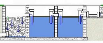
Screw pumps are actively used in various industries. Due to the specifics of the product being manufactured, namely high viscosity and density, these pumps are widely used in the food industry. They are used in winemaking (wine, grapes), in the dairy industry (butter, yogurt, sour cream, ice cream, cream, milk, kefir, cottage cheese, cheeses, margarine, condensed milk), in confectionery (honey, molasses, chocolate, jam, jam, jelly, mousse, cream), for various sauces and seasonings (mustard, ketchup, tomato paste, mayonnaise), etc. They are used in the cosmetics industry (shampoo, liquid soap, hair dyes, lipsticks, creams), the oil industry (petroleum, bitumen-polymer materials, diesel fuel, fuel oil, gasoline), and the chemical industry (detergents, inks, paints, glue , acids, alkalis), pulp and paper industry (flocculants, sludge, paints, paper pulps, tall oil, pulp-water slurry, dyes), as well as in the treatment of domestic and industrial wastewater (flocculants, coagulants, sludge, sludge, lime milk , sapropel).
Selection and maintenance of screw technology
To choose the screw technology that is best suited for the needs of your production, it is worth considering some design features. To decide which device to choose, you should first determine the type of device you need, on which the productivity indicator in cubic meters per hour or liters per minute will depend.
Then determine the required pressure level and height of the liquid column in the area of the pipe, the so-called NPSN indicator. In addition, it is necessary to take into account the chemical composition, density and viscosity, temperature and acid-base balance of the pumped substances. In addition, take into account the amount of abrasives and the possible presence of solid particles in the pumped material.
Three-screw pump design
Well, don’t forget to take into account the voltage and frequency of the power supply network, and the type of transmission mechanism from the motor to the pump. The repair kit included in the equipment list with the most necessary spare parts will be of considerable help.
A screw pump repair kit usually consists of a replacement working screw and a rubber gasket. Therefore, when the auger wears out, you can replace it yourself without having to contact the service department.
Areas of use
Screw technology is used in many areas of industrial production and for domestic needs. Among the main types of screw-type pressure equipment are:
Detailed diagram of a screw pump
- screw pump for water (various variations of a centrifugal pump - vacuum electric pumps, pneumatic screw pump, deep submersible pump);
- food screw pump (milk, oil and fat, confectionery and others);
- devices for the pharmaceutical and chemical industries;
- equipment for the oil and gas and petrochemical industries;
- equipment for power plants;
- equipment for the marine and shipbuilding industry.
An increased level of chemical and mechanical resistance to various non-abrasive inclusions and viscous elements that may be present in the liquid is determined by the elastomeric composition of the stator housing. In addition, it is the composition of the stator housing that determines the maximum permissible temperature range with which screw technology can operate.
For example, in the oil industry, housings are made from NBR elastomer, which can withstand temperatures up to 80 °C. In screw technology for general industrial use, EPDM and HYPALON materials are used, which are able to operate at temperatures up to 120 °C. And in the chemical industry they use FKM type rubber elastomer, which can withstand temperatures up to 150 °C.