When using powered tools and equipment, the operation of which requires the use of working fluid under high pressure, one cannot do without such a technical device as a hydraulic oil station. There are various types of hydraulic oil stations, some of which, if you have the appropriate knowledge and certain skills, can be made with your own hands.
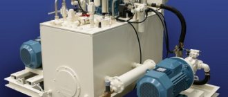
Portable oil station with electric drive for repair work
Design Features
The main purpose of hydraulic oil stations is to convert various types of energy into mechanical energy of fluid flow. Thus, the result of the operation of this device is the transmission of working fluid under a certain pressure to the executive bodies of the equipment connected to the oil station.
Design of a typical hydraulic oil station
The design of any hydraulic oil station consists of the following elements.
Working fluid tank
The inner walls of such a tank, which can be made of ordinary or stainless steel, are processed using sandblasting technology and coated with a double layer of a special polymer composition. Oil stations that operate intensively are equipped with tanks with additional internal partitions, the purpose of which is to facilitate cooling and mixing of the working fluid. The tanks with which any hydraulic oil station is equipped simultaneously perform several functions, namely:
- serve as a reservoir containing working fluid (oil);
- used to cool the working fluid;
- act as a coarse filter in which contaminants contained in the working fluid are deposited;
- serve to separate water and oxygen contained in it from the working fluid;
- used to supply working fluid to pumping equipment.
Hydraulic tank design
Pumping equipment
It can differ both in its design and technical characteristics. One of the most important characteristics of a pump is the flow rate of the working fluid that it is able to provide. This parameter, depending on the type and specific model of pumping equipment, can be in the range of 3–300 l/min. The pumps that are equipped with hydraulic oil stations are one of the following types:
- lamellar;
- gear;
- radial plunger;
- axial piston.
Oil station pump Willy Vogel-DM7
Prime mover
The main function of this element is to convert one type of energy (mechanical energy of compressed air or liquid, electrical, chemical energy of consumed fuel) into the energy of motion - rotational or translational. Depending on what energy the prime mover is intended to convert, it can be:
- pneumatic or hydraulic;
- electrical;
- petrol or diesel.
Pipeline
This is a system of channels, which may include high-pressure hoses, metal pipes, special plates mounted on a butt or modular principle. The pipeline with which each oil station is equipped simultaneously performs several important functions:
- connects the hydraulic pump to the working parts of the oil station (control, distribution and regulating equipment);
- ensures the process of pumping working fluid to the executive body;
- is responsible for returning the working fluid back to the hydraulic tank.
High-pressure pipelines
Drain filter
Its task is to clean the working fluid returning to the hydraulic tank from foreign impurities.
Suction filter
This element cleans the working fluid coming from the storage tank to the hydraulic pump from foreign impurities. This filter, which is installed directly at the outlet of the storage tank, must prevent solid impurities contained in the working fluid from entering the pump line. Since the suction capabilities of the hydraulic pump are limited, the filters located between it and the storage tank must create minimal resistance. Suction filters, some models of which include a magnetic separator or bypass valve in their design, provide only rough cleaning of the working fluid.
Design of some filters for oil stations
Filler neck
The neck is equipped with an air filter that prevents foreign impurities from entering the working fluid at the moment when the hydraulic tank is opened.
Measuring devices
This includes pressure gauges and indicators of the amount of working fluid in the hydraulic tank.
Switchgears
These elements can be one of two types: electro-hydraulic and manually controlled (such devices can consist of one or more sections).
Ultra high pressure hydraulic power plants
Ultra-high pressure oil stations - up to 680 MPa
The new line of Enerprom AQUAflow testing stations is wear resistance, intrinsic safety and accuracy at ultra-high pressure, and the use of water as a hydraulic fluid makes these technical solutions unique.
When creating AQUAflow stations, we selected the best hydraulic components to meet the specific design requirements. The pressure source in AQUAflow test stations is a Haskel pneumatically driven pump, which allows a maximum system outlet pressure of up to 680 MPa. Main features of AQUAflow test stations:
- The pneumatic drive of pumping stations provides the necessary level of safety when carrying out work in places with a high degree of fire and explosion hazard, which is especially important at enterprises in the chemical and petrochemical industries.
- A wide range of stations allows you to select the required model based on the requirements of the task and the capabilities of the pneumatic network of an enterprise or a mobile compressor when used in field conditions.
- The built-in air preparation system allows you to reduce the requirements for the quality of compressed air supplied to the air motor of the pumping station.
- Various options for completing the pumping station: With a tank capacity of up to 60 liters. Without a tank - for testing large-volume containers when connected to a water supply system or to stationary containers, for integration into the technological chain of an enterprise, for example, when injecting chemicals under pressure, etc.
- The entire line of AQUAflow stations is conventionally divided into several series, in accordance with the performance requirements of the pneumatic network of an enterprise or mobile compressor (the number indicates the equivalent power in kW).
Scope of application of AQUAflow pumping stations:
- Oil and gas industry - pressure testing and parameter recording systems, chemical injection units.
- Petrochemical industry - pressure testing units, chemical injection units.
- Automotive and aerospace - cold-pressing systems, hydroforming, standard diesel inspection systems.
- Water transport and shipbuilding - workshop pressure testing units, bolt tensioning and bearing pressing systems.
- Scientific research - imitation of geological conditions and water column pressure, food preservation, research in the field of materials science, autoclaves and optical elements, amplifier units.
- Manufacturers and distributors of high pressure hoses - manually controlled testing units, programmatically controlled testing units, mandrel pressing units, burst pressure tests.
- Manufacturers of pressure vessels and pipelines - pressure testing and recording systems.
ZAO NPO Enerprom will also manufacture a special test pumping station according to your technical requirements. In your request, please indicate the type of working fluid, operating cycle, and purpose of the station.
Enerprom pumping stations with pneumatic drive, AQUAflow 0.3 series
Code
|
Enerprom pumping stations with pneumatic drive, AQUAflow 1.1 series
Code
|
Enerprom pumping stations with pneumatic drive, AQUAflow 4.5 series
| Code | Max. pressure, MPa | Working pressure, MPa | Max. flow level l/min | Working feed level, l/min | Tank volume, l |
| NPR8,3-49,1A-1-UPV-water | 10,8 | 1,2 — 8,3 | 90,2 | 49,1 | — |
| NPR24.0-19.6A-1-UPV-water | 27,7 | 3,4 — 24,0 | 32,7 | 19,6 | — |
| NPR41.2-11.4A-1-UPV-water | 47,4 | 5,9 — 41,2 | 19,7 | 11,4 | — |
| NPR68.7-6.5A-1-UPV-water | 78,9 | 9,8 — 68,7 | 11,5 | 6,5 | — |
Requirements for the pneumatic network: operating pressure - 1.0-6.9 atm, max. pressure - 8.3 atm, optimal air supply - 5000 l/min. All stations have a built-in air preparation unit.
Additionally, you can purchase stainless steel tanks of 10, 30 and 60 liters.
Enerprom pumping stations with pneumatic drive, AQUAflow 6.0 series
| Code | Max. pressure, MPa | Working pressure, MPa | Max. flow level l/min | Working feed level, l/min | Tank volume, l |
| NPR17.2-28.6A-1-UPV-water | 18,8 | 2,5 — 17,2 | 56,0 | 28,6 | — |
| NPR27.5-18.0A-1-UPV-water | 29,8 | 3,9 — 27,5 | 36,0 | 18,0 | — |
| NPR44.6-10.2A-1-UPV-water | 50,1 | 5,9 — 44,6 | 22,0 | 10,2 | — |
| NPR68.7-6.8A-1-UPV-water | 80,9 | 9,8 — 68,7 | 14,0 | 6,8 | — |
| NPR150.0-3.1A-1-UPV-water | 150,0 | 22,1 — 150,0 | 6,0 | 3,1 | — |
Requirements for the pneumatic network: operating pressure - 1.0-6.9 atm, max. pressure - 8.3 atm, optimal air supply - 6400 l/min. All stations have a built-in air preparation unit.
Additionally, you can purchase stainless steel tanks of 10, 30 and 60 liters.
| ← Hydraulic stations for dynamic tools | Emergency hydraulic power stations → |
Principle of operation
Hydraulic oil stations have a number of other names - “hydraulic drives”, “hydraulic stations” or “hydraulic units”. However, no matter what such a device is called, its purpose always remains the same and is to convert energy by controlling the pressure and flow of the working fluid. The type of energy converted, as mentioned above, determines the type of prime mover, which is the main part of any oil station.
Hydraulic diagram of the oil station
If we briefly describe the principle by which the hydraulic station works, it is as follows.
- The prime mover of such a device, consuming a certain energy in accordance with its type, transmits torque from its shaft to the shaft of the hydraulic pump.
- The running hydraulic pump begins to suck the working fluid from the storage tank through the suction filter.
- The working fluid flows through the pipeline system to the corresponding elements of the system. They ensure the distribution of fluid, determine its pressure, and supply it to a hydraulic cylinder or hydraulic motor, which do the main work.
- The working fluid, which has already passed through all the required sections of the system, returns to the storage tank, having previously passed through the drain filter.
Operating principle of the oil station
The main task of the device is to convert energy using compression and liquid flows.
The device functions as follows:
- the engine transfers energy through the rotation of its shaft to the hydraulic one;
- the pump draws the solution from the reservoir using filtration;
- the liquid spreads to the components of the device using pipes, they contribute to its uniform distribution, pressure and supply to the cylinder and motor;
- The working fluid makes a circle in the device and flows into the container using a drain filter.
Advantages of an oil hydraulic station
Instead of an oil system, you can use compressor units, but over them, an oil station has a number of irrefutable advantages.
- Price. The system is compact, which saves money on transportation and installation.
- Cost. The oil system significantly reduces electricity consumption.
- Performance. Hydraulic oil stations are more powerful and efficient.
- Noise. The unit operates much quieter than compressor units.
- Ease of use. Does not require the services of additional specialists.
Hydraulic oil systems are used in various fields due to their versatility and universal design. Thus, they can be used for:
- electrical installation equipment;
- railways and construction sites;
- slurry pumps and pumping stations;
- lifts for large loads.
The principle of operation of a hydraulic station is to pump a substance under compression, so they are used in the case of preliminary tests of pipelines, hydraulic cylinders and various types of equipment. Most often used in the fields of mechanical engineering, metallurgy, agriculture, transport and energy.
Areas and advantages of application
An alternative to using oil stations is to use compressor-type units. However, if we compare installations of these types, then hydraulic power stations for hydraulic drives have a number of advantages.
- Due to the more compact size of such equipment, you have to spend significantly less money on its transportation, installation and operation.
- When operating hydraulic oil stations, significantly less energy resources are consumed, which also leads to a reduction in financial costs.
- Oil stations, compared to compressor equipment, have higher productivity and efficiency of use.
- The wide versatility of such equipment allows it to be connected to devices of various types and power.
- Compared to compressor equipment, oil stations produce significantly less noise during operation.
- Due to the ease of use and maintenance, specially trained, highly qualified personnel are not required to work with such equipment.
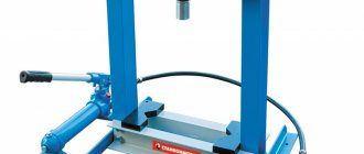
Pumping station as part of a hydraulic pipe bender
Hydraulic stations, naturally, are used to equip equipment on which a hydraulic drive is installed. In fact, with the help of such devices it is possible to operate a mechanism for almost any purpose. That is why hydraulic oil stations are successfully used in many areas. The technical capabilities and versatility of such devices allow them to be used for:
- static type hydraulic tools;
- electrical installation equipment;
- dynamic type hydraulic tools;
- equipment for railway and construction purposes;
- pumps and slurry pumps;
- equipment for drilling operations;
- injection molding machines;
- press equipment;
- devices used to lift and move large and heavy loads;
- equipping test stands;
- technological equipment for various purposes.
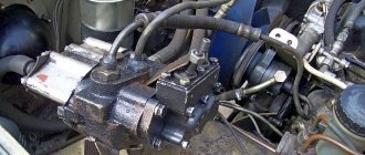
Oil station of lathe
Using hydraulic oil stations, they pump and purify oil, as well as lubricate and cool working elements of equipment for various purposes. Oil stations are used quite actively in cases where it is necessary to test pipeline systems, hydraulic equipment, hydraulic cylinders and various equipment.
If we talk about the areas of activity in which hydraulic oil stations are most actively used, then this should include:
- mechanical engineering;
- metallurgy;
- energy;
- construction;
- Agriculture;
- transport sector.
Parameters and classification
Hydraulic oil stations are divided into various types according to several parameters. So, according to the degree of mobility, devices are distinguished:
- mobile (they are characterized by the most compact size and light weight, due to which they are easily moved even without the use of additional equipment, have the lowest power among devices of similar purpose and are used mainly in the private sphere);
- stationary (large-sized oil stations, which allow creating high pressure on the executive body, are used to equip production enterprises);
- self-propelled (successfully combine the high power of stationary devices and excellent mobility, which is ensured by the presence of a self-propelled wheelbase in their design).
Stationary diesel oil station for pushing installations
Depending on what type of prime mover is used to equip the oil station, such a device can be:
- electrical;
- hydraulic;
- pneumatic;
- gasoline;
- diesel
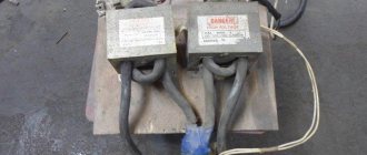
Mobile oil station based on a gasoline internal combustion engine with a capacity of 7.5 liters. With. and productivity 20 l/min
Gasoline oil stations, which are driven by an internal combustion engine, are distinguished by the most compact dimensions among units of this type. The main working element of pneumatic oil stations is the compressor, which must develop a compressed air pressure of at least 0.5 MPa. The most reliable devices used in those areas of activity where strict requirements are imposed on their functioning are hydraulic oil stations, the design of which is supplemented with a pneumatic drive. The design of oil stations of this type is also different in that their working elements are lubricated by spraying the working fluid.
Depending on what type of switchgear is used to equip oil stations, the latter are divided into the following types.
- With manual unloading crane. Through the use of such a valve, the pressure of the working fluid is injected and released in the hydraulic cylinder of the system. Oil stations of this type are equipped with equipment with a spring return mechanism. Such equipment, in particular, includes pipe benders and hydraulic nut cutters.
- With switchgears of two-position type. In oil stations equipped with distributors of this type, the working fluid is pumped under such pressure, which is sufficient not only for the operation of the executive body, but also for returning the fluid back to the storage tank.
- With three-position switchgear. Through the use of such distribution devices, oil stations of this type ensure the functioning of the executive body in three positions: working stroke - holding - return. Such hydraulic stations are used to equip pressing equipment and car lifts.
Feller GS-15-2 double-flow oil station with a manual three-position distributor is used as a drive for double-acting hydraulic equipment
Oil stations also differ depending on the operating pressure they create. So, according to this parameter, hydraulic stations are distinguished:
- weak pressure, the value of which does not exceed 16 MPa;
- medium pressure devices – up to 45 MPa;
- hydraulic power stations providing high pressure – up to 155 MPa;
- heavy-duty oil stations, the value of which exceeds 155 MPa.
According to the control method, oil stations can be one of the following types:
- manual devices, controlled by a special handle;
- electromagnetic type oil stations, the design of which includes a control element such as a push-button station or remote control;
- devices with automatic control, which have both a handle and a push-button station.
Oil station controls HAG-12-20
Depending on the type of hydraulic drive used, oil stations can be one- or two-stage.
- The operation of single-stage oil stations is ensured by a single-flow hydraulic pump. Due to the design features, hydraulic stations of this type allow adjustment of the operating modes of the hydraulic cylinder. Devices of this type are used in cases where the force applied when compressing the pressed object must be the same. In particular, such a hydraulic station is optimally suited for presses used in waste briquetting, wood gluing, pressing and pressing.
- Two-stage oil stations are equipped with dual pumps and a bulkhead hydraulic panel. Hydraulic stations of this type, due to the features of their design, can significantly save energy.
Main components of the oil station.
The oil station consists of the following elements:
- Hydraulic tank . Most often, it is made from stainless steel. The inner walls of the tank are treated twice with a jet of sand, after which they are covered with dense polymers. In devices that will be used on an industrial scale, partitions are installed inside the tank.
Tank functions:
- Cooling liquid
- Main working tank
- Filtration of oil mass
- Settles fluid and removes excess oxygen
- Pump. This element is driven by a motor. The pump can pump from 3 to 300 liters of liquid per minute, depending on the model.
- Prime mover. The main element of the unit. With its help, mechanical energy is converted.
- Pipeline. A system of metal and polymer tubes that can withstand high pressure. Used to move liquid under pressure inside the station and in working tools.
- Drain filter. It is used to clean the waste liquid, which will be refilled into the tank.
- Suction filter. Prevents foreign solid objects from entering the working fluid of the unit. Installation of this element is carried out immediately before starting work. When installing such a filter, the power of the pump should be taken into account. It is necessary to ensure the least resistance to the pump. Some filter models are equipped with specialized valves.
- Filler neck. This element ensures that liquid is poured into the tank of the unit. There is a filter installed inside the neck that cleans the oil mass before use.
- Measuring instruments. Includes a pressure gauge and a working fluid level sensor.
- Distributors. They, in turn, are divided into manual and electrohydraulic.
Recommendations for selection
In order for an oil station for a press, for equipping a lift or any other equipment to effectively cope with the assigned tasks, you should know how to choose it correctly. The modern market offers a wide variety of such devices, the prices of which depend on the following factors:
- the type of prime mover used;
- created pressure and power of the device;
- distribution equipment;
- degree of device mobility;
- manufacturing company.
Typical configurations of hydraulic circuits
The main characteristics of devices of this type include:
- oil station performance or its rated power;
- the volume of the storage tank and the pressure created by the working fluid.
In addition, when choosing hydraulic stations, you need to pay attention to the following parameters:
- drive operating pressure;
- working volume of the piston part of the device;
- speed of the working stroke and its magnitude;
- drive type and equipment configuration options.
When choosing an oil station, take into account the fact that the volume of its storage tank should be one quarter greater than the volume of all channels of the hydraulic equipment that will be connected to such a device.
If the oil station that you are going to purchase will be simultaneously used in conjunction with several actuators, then it is better to choose a multiport pump or a multiport valve as such a device.
When choosing an oil station based on the amount of flow it can provide, this parameter should be compared with the characteristics of the actuators. If the feed amount is insufficient, the actuator will work too slowly; if it is too large, it may simply fail.