September 7, 2016
| Contacts of a specialist for ordering a press for MSW (municipal solid waste) | |
| Lavrenyuk Viktor Andreevich CJSC "StroyMashServis" | +7(495) 785-65-15 ext.253 |
Go to the main page “Hydraulic oil pumping stations”
We offer a comprehensive solution for the disposal of household solid waste (MSW):
Vertical ramming press GPTP-1 (complete with hydraulic station)
| Technical characteristics of the waste compacting press: | |
| Pressing force | 40 tons |
| Characteristics of the power plant | 380V 7.5kW; 220V 1.5kW |
| Press dimensions (L x W x H) | 2190 mm - 1100 mm - 4690 mm |
| Loading window dimensions | 1990 mm - 780 mm |
| Press weight | 3670 kg |
| Rod stroke | 1800 mm |
| Full cycle time | 60 seconds |
| Bale tying | Manual |
| Hydraulic cylinder | TsG-160.100x1800.24 - 2 pcs. |
Industrial press designed for processing a large number of different wastes. The model is equipped with two working cylinders with a total pressing force of 40 tons, allowing you to create compact and dense bales.
The operating cycle is no more than 60 seconds. Thanks to the hydraulic cylinder stroke of 1800 mm, the press is in demand for packaging feathers, cardboard, thin-sheet metal, barrels, flasks, cans, shavings and other solid household waste. It is possible to process tires for packaging and subsequent transportation.
The press is equipped with a hydraulic pump station SNEE20-80I200T2
P=20 MPa. Q=80 l/min. N=7.5 kW. 1500 rpm 380V Tank 200 l.
Double pump (made in Italy), double safety valve VD/CTP-05 (made in Italy)
Types of oil stations for press
Oil stations for hydraulic presses can be divided into two main types:
- Single threaded
- Dual-flow
Single-flow stations are a simple unit with the necessary parameters; the operating cycle of such a station is fixed and does not depend on the forces applied by the hydraulic cylinder of the press. Double-flow stations allow you to reduce the press cycle by using two pumps. Usually one pump has a high flow rate and low pressure, it is necessary in order to accelerate the hydraulic cylinder of the press at idle or under light loads. The second pump has a small flow but high pressure. With its help, the press creates maximum force. That is, both pumps operate at idle and light loads, allowing the hydraulic cylinder rod to be quickly lowered, and at the moment when it is necessary to create a large force, the low-pressure pump transfers hydraulic fluid to the hydraulic cylinder cavity, and the high-pressure pump operates with maximum effort.
What is an oil station and where is it used?
Oil station (hydraulic pumping station) is a technical system that converts various types of energy into mechanical fluid energy. The type of energy converted depends on the engine that enters the station.
What may be included in an oil station
The hydraulic station includes basic (engine, pump, hydraulic tank, high pressure hose, drain filter) and additional (by type of purpose and operating conditions: filter, relays, sensors and much more) components:
1. Main components of the oil station:
- engine – is the drive for the pumping system and can run on electricity, gasoline (ICE), diesel (ICE) or pneumatics;
- pump – converts kinetic energy into mechanical energy of the fluid. By type they differ into: gear, vane, axial plunger, radial plunger or plunger pump;
- hydraulic tank - a hydraulic tank is a place for storing working fluid, as well as for cooling the working fluid and removing contaminants by settling;
- High pressure hoses (HHP) are flexible hoses that can withstand high pressure of the working fluid in hydraulics. Thanks to the RVD, the working fluid reaches the moving elements of hydraulic equipment.
- drain filter - designed to filter hydraulic oil when the working fluid returns from the hydraulic engine.
2. Additional or optional components:
- suction filter – allows you to filter hydraulic oil from the hydraulic tank to the pump;
- pressure filter – allows you to filter hydraulic oil from the pump;
- pressure control devices – safety, unloading, reducing valves;
- hydraulic flow control devices - throttles , flow regulators and other types of valves;
- working fluid distribution devices - check valves , hydraulic distributors, as well as other types of devices;
- air or water heat exchanger - allows you to cool the working fluid;
- tubular electric heater – designed to heat the working fluid. Installed on a hydraulic tank;
- Sensors are elements of a signaling, measuring, regulating or control device of a system. Used to measure pressure, flow and temperature of hydraulic oil;
- control panel - a device for controlling the hydraulic equipment of an oil station ( hydraulic distributors , pressure multipliers and much more).
Operating principle using the example of an electric oil station
The electric motor transmits torque to the hydraulic pump through a clutch. The working fluid is sucked by the pump from the hydraulic tank through the filter, then it is supplied through the high pressure hose to the control and distribution hydraulic equipment to the actuator equipment. After the work is done, the hydraulic oil is returned to the hydraulic tank.
Main technical characteristics
| Characteristic | Note |
| Nominal working pressure (MPa, bar) | the highest excess pressure at which the hydraulic station operates |
| Nominal flow (l/min) | the largest volume of liquid pumped by the oil station per unit of time |
| Hydraulic tank volume (liters/l) | maximum volume of oil that the hydraulic tank can hold |
| Motor power (kW) | amount of engine work performed per unit of time |
Types and scope of oil stations
By type of oil station there are:
| By design | By motor | According to nominal pressure |
|
|
|
Oil stations provide hydraulic energy:
- Jacks and synchronized lifting/lowering/positioning systems;
- Impact wrench systems;
- Construction and railway equipment ;
- Press equipment;
- Control systems, movement of large-sized and large-tonnage objects;
- Test benches for testing hydraulic cylinders, hydraulic equipment, tanks and pipeline elements;
- When supplying liquid lubricant to equipment components for cooling and lubrication, as well as when cleaning and filtering oils on process equipment.
Production of oil stations
The website's electronic catalog presents ready-made pumping stations with various technical characteristics. However, at the customer's request, we can assemble equipment according to an individual plan. The client decides which key installation parameters he needs. If you have previously installed an imported station, you can simply collect documentation for it and transfer it to our specialists. They will create a similar installation, in no way inferior to the original. Thus, you can significantly save on the purchase of industrial equipment.
Operation of a waste disposal press (efficiency proven in practice!)
Press cabinet, hydraulic cylinders, hydraulic station, control panel - all of our own production(GC "Stroymashservice")
Press cabinet body before and after. Ready-made compactor solution for solid waste waste
Other completed orders and ready-made solutions for hydroelectric power stations:
Mobile hybrid hydraulic station (can run on both gasoline and electricity)
Hydraulic station MS-202 2SNBRSNVR10-50I100T2
To order an oil station you need to specify the basic parameters: | |
| To order a hydraulic station with individual technical characteristics, please fill out a form and send it by email with the subject line “For Lavrenyuk: Ordering a hydraulic station.” We will definitely contact you regarding this order. |
Main technical characteristics of hydraulic power stations for the press
- Working pressure (nominal) – from 12 to 40 MPa.
- Maximum productivity (feed) – up to 150 liters per minute.
- Drive motor power – from 0.75 or 50 kW.
- The volume of the hydraulic tank is from 10 to 4000 liters.
- Control method – manual, semi-automatic and automatic.
Depending on the production capacity and assigned tasks, it is necessary to select a pumping station with optimal parameters. Otherwise, the oil station for the press will not be able to cope with its functions or there will be excessive reserve. Most equipment models belong to open hydraulic systems, which allows them to be effectively used in various fields of production: mechanical engineering, food industry, woodworking, machine tool building and others.
It is most profitable to order hydraulic pumping stations from, since we offer a wide range of products at affordable prices. If necessary, we assemble equipment according to an individual project, taking into account all the wishes of the customer.
Design and principle of operation of an oil station for a press
Hydraulic Press
In technology, a press is a device designed to apply pressure to any external object.
With the help of a press, pressure of a certain direction and force is applied to an object: the object can be pinched, held, squeezed, and it can be given a certain shape. The required pressure is ensured by the fact that the press - in the general case - consists of two main parts: a stationary frame and a moving working element that presses the object against the frame.
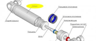
The working element can be pressed by a special motor called a hydraulic cylinder. It is here that an external pressure force is generated due to the pressure of the working fluid inside the device itself. Presses built on the basis of hydraulic cylinders are also called hydraulic.
Hydraulic presses and hydraulic cylinders from
Our company has been producing hydraulic baling presses for about a quarter of a century. Since 1994, hydraulic cylinders produced by us have also been successfully used in the design of recycling presses: waste paper presses, alligator shears, scrap baling presses - and everywhere, thanks to our quarter-century of experience, their technical characteristics optimally correspond to the tasks and working conditions. We guarantee 30,000 cycles of uninterrupted operation and vouch for the quality of our products.
But in order for the hydraulic cylinder to successfully function as intended, it is necessary to pump working fluid into it. The device that ensures this process is called an oil station (hydraulic pump station or simply a hydraulic station).
Oil station operation
Let us describe the design and operating principle of the oil station for the press step by step:
- the primary engine is powered from an external energy source, which rotates the shaft of the hydraulic pump;
- the pump, through a suction filter, supplies working fluid from the storage tank through a pipeline system to the hydraulic cylinder;
- the hydraulic cylinder moves the working element of the press, thereby providing the required pressure on the object;
- After completing the necessary work, the press and the hydraulic cylinder itself return to their original position. And the working fluid is drained from the hydraulic cylinder into the storage tank through another filter;
- the cycle repeats.
Types and advantages of oil stations for the press
The prime mover for press oil is most often liquid fuel (gasoline or diesel) or electric. Pneumatic and hydraulic motors are also common. Although, in principle, any type of energy can be used - from solar and wind to tidal and geothermal.
Pumps can also be of any types and designs. The most commonly used pumps are axial piston, radial plunger, vane and gear pumps.
Other equipment (pipeline, control, measuring, storage and other additional) can also have a wide variety of designs.
An alternative to the use of hydraulic drives for oil stations is the use of compressor units. However, press oil stations have a number of advantages.
- compact dimensions;
- less energy consumption;
- higher productivity and application efficiency;
- versatility, allowing you to connect them to devices of various types and power;
- lower noise level than compressor units;
- ease of use and maintenance.
Design Features
The main purpose of hydraulic oil stations is to convert various types of energy into mechanical energy of fluid flow. Thus, the result of the operation of this device is the transmission of working fluid under a certain pressure to the executive bodies of the equipment connected to the oil station.
The design of any hydraulic oil station consists of the following elements.
Working fluid tank
The inner walls of such a tank, which can be made of ordinary or stainless steel, are processed using sandblasting technology and coated with a double layer of a special polymer composition. Oil stations that operate intensively are equipped with tanks with additional internal partitions, the purpose of which is to facilitate cooling and mixing of the working fluid. The tanks with which any hydraulic oil station is equipped simultaneously perform several functions, namely:
- serve as a reservoir containing working fluid (oil);
- used to cool the working fluid;
- act as a coarse filter in which contaminants contained in the working fluid are deposited;
- serve to separate water and oxygen contained in it from the working fluid;
- used to supply working fluid to pumping equipment.
Pump equipment
It can differ both in its design and technical characteristics. One of the most important characteristics of a pump is the flow rate of the working fluid that it is able to provide. This parameter, depending on the type and specific model of pumping equipment, can be in the range of 3–300 l/min. The pumps that are equipped with hydraulic oil stations are one of the following types:
- lamellar;
- gear;
- radial plunger;
- axial piston.
Prime mover
The main function of this element is to convert one type of energy (mechanical energy of compressed air or liquid, electrical, chemical energy of consumed fuel) into the energy of motion - rotational or translational. Depending on what energy the prime mover is intended to convert, it can be:
- pneumatic or hydraulic;
- electrical;
- petrol or diesel.
Pipeline This is a system of channels, which may include high-pressure hoses, metal pipes, special plates mounted on a butt or modular principle. The pipeline with which each oil station is equipped simultaneously performs several important functions:
- connects the hydraulic pump to the working parts of the oil station (control, distribution and regulating equipment);
- ensures the process of pumping working fluid to the executive body;
- is responsible for returning the working fluid back to the hydraulic tank.
Drain filter
Its task is to clear the working fluid returning to the hydraulic tank from foreign impurities.
Suction filter
This element cleans the working fluid coming from the storage tank to the hydraulic pump from foreign impurities. This filter, which is installed directly at the outlet of the storage tank, must prevent solid impurities contained in the working fluid from entering the pump line. Since the suction capabilities of the hydraulic pump are limited, the filters located between it and the storage tank must create minimal resistance. Suction filters, some models of which include a magnetic separator or bypass valve in their design, provide only rough cleaning of the working fluid.
Filler neck
The neck is equipped with an air filter that prevents foreign impurities from entering the working fluid at the moment when the hydraulic tank is opened.
Measuring devices
This includes pressure gauges and indicators of the amount of working fluid in the hydraulic tank.
Switchgears
These elements can be one of two types: electro-hydraulic and manually controlled (such devices can consist of one or more sections).
Main types of hydraulic oil stations
Hydraulic oil stations are divided according to several parameters. Depending on the type of movement, they are:
- mobile type;
- stationary type;
- self-propelled type.
The first type is characterized by compact dimensions and is easy to transport. Mobile oil stations have low power and are used in the private sector.
Stationary devices are used in industry. Such oil stations have large dimensions and operate at high power.
Self-propelled hydraulic oil stations combine the advantages of the two previous types. They have both high power and means of transportation, and in particular wheels.
Depending on the prime mover, the oil station is:
- hydraulic;
- electrical;
- pneumatic;
- gasoline;
- diesel
Oil stations based on a gasoline engine are the most compact. To operate a pneumatic oil station, a compressor is required, the minimum operating pressure of which is 0.5 MPa. Hydraulic oil stations based on a pneumatic drive are used in enterprises that have strict operational requirements, and in particular, in petrochemical or mining plants. Such oil stations have a longer service life and use devices that provide system lubrication by spraying the working fluid.
Depending on the type of distributors, hydraulic oil stations are:
- With the presence of a manual unloading crane - they pump and release pressure into the hydraulic cylinder device. Used when working with equipment that has a spring return, such as a pipe bender or nut cutter.
- An oil station with two-position distributors pumps up such pressure that it can not only supply oil for operation, but also ensure its return back to the system. Used for equipment that has a two-position action.
- Devices with a three-position distributor are the most popular. They allow you to work in the position of the working stroke - hold and return. Used to operate presses.
According to pressure, oil stations are:
- low pressure - up to 16 MPa;
- medium pressure - up to 45 MPa;
- high pressure oil station - up to 155 MPa;
- heavy-duty pressure - more than 155 MPa.
Hydraulic oil stations differ in the way they are controlled and are:
- manual type;
- electromagnetic type;
- automatic type.
In the first type of oil stations, the operation is controlled using a handle. The electromagnetic control method involves pressing a button station, which is located on the oil station, or using a remote control on the buttons.
The third type of control is a combination of the two previous methods. The operation can be controlled either with a remote control or with a handle.
Depending on the type of hydraulic drive, oil stations are:
- single-stage;
- two-stage.
Single-stage ones have a single-flow pump. Such stations allow you to regulate the speed and operating mode of the hydraulic cylinder. Oil stations of this type are used in cases where it is necessary to apply equal forces to compress the pressed body. For example, when making briquettes from waste or garbage. They are also used in the production of dry ice, gluing wood beams, pressing or pressing.
Two-stage oil stations consist of a two-stage cycle. They are distinguished by the presence of a dual pump and a bulkhead hydraulic panel. Such stations significantly save electricity.
Parameters and classification
Hydraulic oil stations are divided into various types according to several parameters. So, according to the degree of mobility, devices are distinguished:
- mobile (they are characterized by the most compact size and light weight, due to which they are easily moved even without the use of additional equipment, have the lowest power among devices of similar purpose and are used mainly in the private sphere);
- stationary (large-sized oil stations, which allow creating high pressure on the executive body, are used to equip production enterprises);
- self-propelled (successfully combine the high power of stationary devices and excellent mobility, which is ensured by the presence of a self-propelled wheelbase in their design).
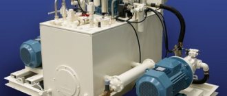
Stationary diesel oil station for pushing installations
Depending on what type of prime mover is used to equip the oil station, such a device can be:
- electrical;
- hydraulic;
- pneumatic;
- gasoline;
- diesel
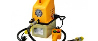
Mobile oil station based on a gasoline internal combustion engine with a capacity of 7.5 liters. With. and productivity 20 l/min
Gasoline oil stations, which are driven by an internal combustion engine, are distinguished by the most compact dimensions among units of this type. The main working element of pneumatic oil stations is the compressor, which must develop a compressed air pressure of at least 0.5 MPa. The most reliable devices used in those areas of activity where strict requirements are imposed on their functioning are hydraulic oil stations, the design of which is supplemented with a pneumatic drive. The design of oil stations of this type is also different in that their working elements are lubricated by spraying the working fluid.
Depending on what type of switchgear is used to equip oil stations, the latter are divided into the following types.
- With manual unloading crane. Through the use of such a valve, the pressure of the working fluid is injected and released in the hydraulic cylinder of the system. Oil stations of this type are equipped with equipment with a spring return mechanism. Such equipment, in particular, includes pipe benders and hydraulic nut cutters.
- With switchgears of two-position type. In oil stations equipped with distributors of this type, the working fluid is pumped under such pressure, which is sufficient not only for the operation of the executive body, but also for returning the fluid back to the storage tank.
- With three-position switchgear. Through the use of such distribution devices, oil stations of this type ensure the functioning of the executive body in three positions: working stroke - holding - return. Such hydraulic stations are used to equip pressing equipment and car lifts.
Feller GS-15-2 double-flow oil station with a manual three-position distributor is used as a drive for double-acting hydraulic equipment
Oil stations also differ depending on the operating pressure they create. So, according to this parameter, hydraulic stations are distinguished:
- weak pressure, the value of which does not exceed 16 MPa;
- medium pressure devices – up to 45 MPa;
- hydraulic power stations providing high pressure – up to 155 MPa;
- heavy-duty oil stations, the value of which exceeds 155 MPa.
According to the control method, oil stations can be one of the following types:
- manual devices, controlled by a special handle;
- electromagnetic type oil stations, the design of which includes a control element such as a push-button station or remote control;
- devices with automatic control, which have both a handle and a push-button station.
Oil station controls HAG-12-20
Depending on the type of hydraulic drive used, oil stations can be one- or two-stage.
- The operation of single-stage oil stations is ensured by a single-flow hydraulic pump. Due to the design features, hydraulic stations of this type allow adjustment of the operating modes of the hydraulic cylinder. Devices of this type are used in cases where the force applied when compressing the pressed object must be the same. In particular, such a hydraulic station is optimally suited for presses used in waste briquetting, wood gluing, pressing and pressing.
- Two-stage oil stations are equipped with dual pumps and a bulkhead hydraulic panel. Hydraulic stations of this type, due to the features of their design, can significantly save energy.
Typical hydraulic station diagram
- Tank
- Pump
- Pressure filter
- Suction filter
- Drain filter
- Safety valve
- Hydraulic distributor
Tank
The hydraulic tank serves to store the working fluid circulating in the hydraulic system, release air from it and partially cool it. When designing a tank, normal conditions for suction and deaeration of the working fluid must be ensured. The size and shape of the tank are closely related to the temperature regime in the hydraulic drive, since some of the thermal energy released during the operation of the hydraulic system is transferred to the environment through the walls of the tank. During the production process, all tanks undergo mandatory leak testing and subsequent painting using special technologies and materials that are resistant to hot oil. To monitor the fluid level in the hydraulic tank, there is a visual level indicator. The fluid is drained through a drain hole or tap located at the bottom of the hydraulic tank. We have developed hydraulic tanks of various designs and sizes, which you can familiarize yourself with in the corresponding section of the catalog.
Pump
Hydraulic pumps are power elements of a hydraulic drive that convert the mechanical energy of rotation of the drive shaft into the hydraulic energy of the flow of working fluid, which is supplied through pipelines to the hydraulic motors. The most common type of pump unit for pumping hydraulic fluid into the system is made on the basis of a gear pump. Operating pressure range from 2 to 310 bar, flow rates from 0.5 to 100 l/min (standard range of pumps) and above 100 l/min. up to 5000 l/min. (supplied upon request). Such solutions are widely used in mobile and industrial technology. The next type of pumping units is with vane pumps. This type of pump provides more uniform flow compared to gear pumps and greater productivity. The operating pressure range is somewhat lower and rarely exceeds 160 bar (the imported industry produces pumps of 210 bar or more). Vane pumps can be produced as single- and double-flow, with fixed and adjustable performance, as well as a through shaft for installing an additional pump, for example, a gear pump. This type of pump is common in machine tools and hydraulic drives for a wide range of applications. Pumping units with axial piston pumps are characterized by compactness and the resulting minimum weight. Due to the use of working bodies with small radial dimensions and, therefore, a relatively small moment of inertia, such machines make it possible to quickly regulate the rotation speed. In addition, the advantages of axial piston pumps include the ability to operate at high pressures (up to 400 bar) and high efficiency values (up to 95%). Among the disadvantages of machines of this type, it should be noted the considerable cost, complexity of the design, as well as significant feed pulsation. Axial piston pumps are most widely used in hydraulic drives of machines operating under medium and heavy external load conditions with high switching frequencies. It is possible to manufacture units with 2-3 in-line pumps driven by one electric motor, which makes it possible to reduce the size of the system and use various combinations of performance and pressure to solve a wide range of problems.
