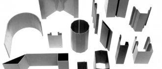
Learn how to make a truncated cone or round transition with your own hands
In everyday life, of course, you have to do everything yourself if you have your own yard, house, dacha, construction. Perhaps a little advice in the article with sections on how to make a cone or transition with your own hands will help you around the house, without extra costs.
For example, let's take a bucket made of metal or other material. It has two different diameters. The smallest one is made at the bottom with a closed bottom. The bucket is made in the shape of a truncated cone.
Round transitions are used everywhere, for example ventilation, from one round diameter to another round diameter, also in the form of a truncated cone.
Take a random cone size with a diameter of 250 x 150 mm and a height of 180 mm (you have your own dimensions). Figure A.
We make a pattern of the part on which we will create the transition. The first diameter of 250 mm is multiplied by P = 3.14 and the result is 785 mm. Then we divide 785 mm into 10 parts. We divide the resulting amount of 78.5 mm into 2 parts. See the example in the figure.
Next, we draw a part template, using it we will make a cone pattern. Figure B.
We outline the part template 10 times. You get a development of a truncated cone. Figure B.
Locks or connections are indicated in yellow. How will you connect your right. Locks for tightness, can be used with bolts, self-tapping screws, welding seam, glue, overlap. The only thing we don’t forget to add to the connection. When you have completely traced the template, round off the straight ends slightly.
Next, after assembling the cone, bead the edge of the cone along the edges with a hammer to secure the straight shell. It is better to make the height of the shell more than 60 mm.
It is better to make a sample of the first pattern from paper cardboard, so as not to spoil the material.
Source
Calculators for calculating cone development sizes
Sometimes, while performing certain chores, the master is faced with the problem of making a cone - full or truncated. This could involve operations on, say, thin sheet metal, flexible plastic, regular fabric, or even paper or cardboard. And the tasks are very different - making casings, adapters from one diameter to another, canopies or deflectors for a chimney or ventilation, funnels for gutters, a homemade lampshade. Or maybe even just a fancy dress for a child or crafts assigned by the labor teacher at home.
Calculators for calculating cone development sizes
To roll a three-dimensional figure with given parameters from a flat material, you need to draw a development. And for this you need to calculate mathematically and transfer graphically the necessary exact dimensions of this flat figure. We will look at how this is done in this publication. Calculators for calculating the dimensions of the cone sweep will help us in this matter.
Pattern for a cone
Home > Geometry > Pattern for a cone
11/19/2012 // Vladimir Trunov
Instead of the word “pattern”, “reamer” is sometimes used, but this term is ambiguous: for example, a reamer is a tool for increasing the diameter of a hole, and in electronic technology there is the concept of a reamer. Therefore, although I am obliged to use the words “cone development” so that search engines can find this article using them, I will use the word “pattern”.
Creating a pattern for a cone is a simple matter. Let's consider two cases: for a full cone and for a truncated one. The picture (click to enlarge) shows sketches of such cones and their patterns. (I should immediately note that we will only talk about straight cones with a round base. We will consider cones with an oval base and inclined cones in the following articles).
Full cone
Designations:
- — diameter of the base of the cone;
- — height of the cone;
- — radius of the arc of the pattern;
- - central corner of the pattern.
The pattern parameters are calculated using the formulas: ; ; Where .
Frustum
Designations:
- - diameter of the larger base of the cone;
- - diameter of the smaller base of the cone;
- — height of the cone;
- — radius of the outer arc of the pattern;
- — radius of the inner arc of the pattern;
- - central corner of the pattern.
Formulas for calculating pattern parameters: ; ; ; Where . Note that these formulas are also suitable for a full cone if we substitute .
Cone apex angle
Sometimes when constructing a cone, the value of the angle at its vertex (or at the imaginary vertex, if the cone is truncated) is fundamental. The simplest example is when you need one cone to fit tightly into another. Let's denote this angle with a letter (see picture). In this case, we can use it instead of one of three input values: , or . Why “together ” and not “together ” ? Because to construct a cone, three parameters are enough, and the value of the fourth is calculated through the values of the other three. Why exactly three, and not two or four, is a question beyond the scope of this article. A mysterious voice tells me that this is somehow connected with the three-dimensionality of the “cone” object. (Compare with the two initial parameters of the two-dimensional object “circle segment”, from which we calculated all its other parameters in the article Geometry of a Circle.)
Below are the formulas by which the fourth parameter of the cone is determined when three are given.
- Given ; Then .
- Given ; Then .
- Given ; Then .
- Given ; Then .
Pattern construction methods
- Calculate the values on a calculator and construct a pattern on paper (or directly on metal) using a compass, ruler and protractor.
- Enter formulas and source data into a spreadsheet (for example, Microsoft Excel). Use the obtained result to create a pattern using a graphic editor (for example, CorelDRAW).
- use my Cones , which will draw on the screen and print a pattern for a cone with the given parameters. This pattern can be saved as a vector file and imported into CorelDRAW.
Not parallel bases
As for truncated cones, the Cones program currently creates patterns for cones that have only parallel bases. For those who are looking for a way to construct a pattern for a truncated cone with non-parallel bases, here is a link provided by one of the site visitors: Truncated cone with non-parallel bases.
geometric formulas
Circle geometry
Pattern of an oval and inclined cone
Related Posts
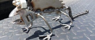
DIY sheet metal bending technology
In the process of building a house or cottage, there is often a need to equip drains, sewers, and metal frames.
When manufacturing such products, it is necessary to give the flat workpiece the necessary spatial shape. Advice from experienced craftsmen on how to bend a sheet of metal at home will allow you to produce good quality structures that will last a long time.
Bending technology - basic information
Metal bending is performed without welding seams, which avoids corrosion in the future and produces a product of increased strength. Deformation does not require significant effort and is usually performed in a cold state.
The exception is hard materials such as duralumin or carbon steels. Sheet metal bending technology is developed according to the assigned tasks in such options as:
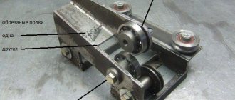
Forming a cone on a pipe using rotary forging
Rotary forging technology
Rotary forging machines are high-frequency presses with a limited stroke. The stroke of the tools is regulated by limiters. This kinematics is located in the center of the rotary forging mill, in the so-called reducing head or rotor (drum)
Rotary forging of metal is an incremental method, since the deformation of the workpiece occurs gradually, through many small steps. These methods have undeniable advantages over continuous ones, in view of the fact that they allow more uniform deformation of the workpiece. This technology also allows for a deeper degree of deformation of the workpiece due to the fact that the potential for changing the shape of the material is distributed over the entire cross section.
Operating principle of the machine for forming a cone on a pipe:
The working tool (die, tooling, forging tool) is located concentrically around the workpiece (pipe) being processed.
The rotor with strikers can rotate. When rotating, the strikers strike diametrically opposite columns (rods), which stand along the perimeter of the rotor. The striker transmits the impact to the material, which is processed and the metal begins to flow.
Forging tools oscillate at high frequency and low stroke as the rotor (drum) rotates. The tools work synchronously (at the same time). The tool set consists of four segments (there is also a simplified model with two tools). To prevent the workpiece material from flowing into the gaps between the tool segments, the tool drum is rotated slowly relative to the workpiece. When producing asymmetrical parts, there is no need for rotation.
Another advantage of incremental processing is the minimization of friction. The working (forging) tool has short-term contact with the material and produces very small shifts relative to the part and the tool. The efforts are compensated by the elasticity of the workpiece. Due to this, when deforming using this technology, it is sufficient to use coolant in a closed cycle to stabilize the temperature and clean the working area.
Advantages of using rotary forging technology:
— High repeatability of final products during production: the tolerances provided by the technology are so small that subsequent cutting processing is not required. This directly reduces material losses, production time and, as a result, the cost of the final product.
— Wide range of image imaging capabilities and weight optimization: this technology allows you to process a diverse range of shapes, both externally and internally. Average weight savings for rotary forged products range from 30% to 50% compared to traditional methods.
— High quality parts : technology ensures a continuous flow of fibers in the workpiece material. Cold forging increases the strength of the final products. The surface of the product after rotational forging is comparable to ground surfaces.
— High degrees of deformation are acceptable even for processing brittle materials : the technology allows you to achieve high degrees of deformation without heating the workpiece. Rotary forging is suitable for working with brittle materials, thanks to the “successful” stress tensor during deformation and the constant flow of deformation.
— Cold and warm forming : during rotational forging, the workpiece is gradually introduced into the working area; this technology can be used in both cold and semi-hot and hot temperature ranges.
— Ecology : unlike other molding methods, this method allows you to do without an additional layer of lubricant, since the cooling lubricant circulates in a closed cycle.
— Quick changeover : rotary forging machines are quickly readjusted. Changing the working tool to set it up for processing other workpieces takes the operator a few minutes.
— Short cycles and high availability : horizontal positioning and small installation area of working units makes it easy to build efficient production lines for the production of large series of products with continuous operation in two or three shifts with high final productivity.
Calculators for calculating cone development sizes
A few words about the calculated parameters
It will not be difficult to understand the calculation principle by understanding the following diagram:
A truncated cone with defining dimensions and its development. A truncated cone is shown, but with a full one - the principle does not change, and calculations and construction become even simpler.
So, the cone itself is determined by the radii of the bases (lower and upper circles) R1 and R2 , and the height H. It is clear that if the cone is not truncated, then R2 is simply equal to zero.
The letter L indicates the length of the side (generator) of the cone. In some cases, it is already known - for example, you need to make a cone according to a sample or cut out material to cover an existing frame. But if it is unknown, it doesn’t matter, it’s easy to calculate.
The scan is shown on the right. For a truncated cone, it is limited by the sector of the ring formed by two arcs, external and internal, with radii Rb and Rs . For a full cone, Rs will also be zero. It is clearly seen that Rb = Rs + L
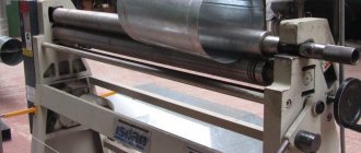
Metal bending on rollers
07 Dec 2013 Category: Mechanics |
Recently, I have received several requests from blog readers for help in solving the same problem: how to determine the final location of the middle roller (roll) when working on three-roll sheet bending rolls and profile benders...
...relative to the position of the outer rollers (rolls), which will ensure bending (rolling) of the workpiece with a certain specified required radius? The answer to this question will increase labor productivity when bending metal by reducing the number of runs of the workpiece until a suitable part is obtained.
In this article you will find theoretical
solving the problem. Let me make a reservation right away: I did not apply this calculation in practice and, accordingly, did not check the effectiveness of the proposed method. However, I am confident that in certain cases metal bending can be done much faster using this technique than usual.
Most often, in normal practice, the final location of the movable central roller (roll) and the number of passes until a suitable part is obtained is determined by the “poke method”. After a long (or not so long) development of the technological process on a test part, the coordinate of the position of the central roller (roll) is determined, which is used for further reconfiguration of the rollers, producing a batch of these parts.
The method is convenient, simple and good for a significant number of identical parts - that is, for mass production. In single or “very small-scale” production, when it is necessary to bend different profiles or sheets of different thicknesses with different radii, the loss of time for adjustment “at random” becomes catastrophically huge. These losses are especially noticeable when bending long (8...11 m) workpieces! While you make the pass..., while you take measurements..., while you rearrange the position of the roller (roller)... - and all over again! And so a dozen times.
Calculation in Excel of the location of the moving middle roller
Launch MS Excel or OOo Calc and get started!
General rules for formatting spreadsheets that are used in blog articles can be found here.
First of all, I would like to note that sheet bending rollers and profile benders of different models may have movable outer rollers (rollers), or they may have a movable middle roller (roller). However, for our task this is not of fundamental importance.
The figure below shows the calculation diagram for the problem.
At the beginning of the process, the part to be rolled lies on two outer rollers (rolls) having a diameter D
. Middle roller (roll) with diameter d
brought
until it touches the top of the workpiece
.
Next, the middle roller (roller) moves down to a distance equal to the design size H
, the roller rotation drive is turned on, the workpiece is rolled, the metal is bent, and the output is a part with a given bending radius R
!
H
correctly, quickly and accurately . This is what we will do.
Initial data:
1. Diameter of the movable upper roller (roller) /for reference/ d
write in mm
to cell D3: 120
2. Diameter of support rollers (rolls) with rotation drive D
to cell D4: 150
3. Distance between the axes of the support outer rollers (rolls) A
to cell D5: 500
4. Height of the section of the part h
to cell D6: 36
5. Internal bending radius of the part according to drawing R
to cell D7: 600
Calculations and actions:
6. Calculate the estimated vertical feed of the upper roller (roll) H calc.
in mm excluding springing
in cell D9: =D4/2+D6+D7- ((D4/2+D6+D7)2- (D5/2)2)(½)
=45.4
7. Adjust the rollers to this size H calculated
and make the first run of the workpiece. We measure or calculate the resulting internal radius from the chord and height of the segment, which we denote by R
and write down the resulting value in mm
to cell D10: 655
8. We calculate what the calculated theoretical vertical feed of the upper roller (roll) should be H 0calc
in mm for the manufacture of a part with a radius R
excluding springing
in cell D11: =D4/2+D6+D10- ((D4/2+D6+D10)2- (D5/2)2)(½)=41,9
H0calc =D/2+h+
R0 - ((D/2+h+ R0 )2- (A/2)2)(½) 9. But a part with an internal bending radius R was obtained with the upper roll lowered by size Hcalc , and not H 0calc .
We calculate the correction for back springing
x
in mm
Making metal cones
07 Dec 2013 Category: Mechanics |
Recently, I have received several requests from blog readers for help in solving the same problem: how to determine the final location of the middle roller (roll) when working on three-roll sheet bending rolls and profile benders...
...relative to the position of the outer rollers (rolls), which will ensure bending (rolling) of the workpiece with a certain specified required radius? The answer to this question will increase labor productivity when bending metal by reducing the number of runs of the workpiece until a suitable part is obtained.
In this article you will find theoretical
solving the problem. Let me make a reservation right away: I did not apply this calculation in practice and, accordingly, did not check the effectiveness of the proposed method. However, I am confident that in certain cases metal bending can be done much faster using this technique than usual.
Most often, in normal practice, the final location of the movable central roller (roll) and the number of passes until a suitable part is obtained is determined by the “poke method”. After a long (or not so long) development of the technological process on a test part, the coordinate of the position of the central roller (roll) is determined, which is used for further reconfiguration of the rollers, producing a batch of these parts.
The method is convenient, simple and good for a significant number of identical parts - that is, for mass production. In single or “very small-scale” production, when it is necessary to bend different profiles or sheets of different thicknesses with different radii, the loss of time for adjustment “at random” becomes catastrophically huge. These losses are especially noticeable when bending long (8...11 m) workpieces! While you make the pass..., while you take measurements..., while you rearrange the position of the roller (roller)... - and all over again! And so a dozen times.
Sheet metal rolling
| Metal thickness | Quantity, pcs | Price |
| 0.8-1 mm | from 50 to 1000 | from 200 rub. |
| 1.2-1.5 mm | from 50 to 1000 | from 230 rub. |
| 2-2.5 mm | from 50 to 1000 | from 250 rub. |
| 3 mm | from 50 to 1000 | from 280 rub. |
Source: https://rem-serv.com/izgotovlenie-metallicheskih-konusov/
Inclined cone development
Let us consider the procedure for constructing a scan of the lateral surface of an inclined cone using the approximation (approximation) method.
- We inscribe the hexagon 123456 into the circle of the base of the cone. We connect points 1, 2, 3, 4, 5 and 6 with the vertex S. The pyramid S123456, constructed in this way, with a certain degree of approximation is a replacement for the conical surface and is used as such in further constructions.
- We determine the natural values of the edges of the pyramid using the method of rotation around the projecting straight line: in the example, the i axis is used, perpendicular to the horizontal projection plane and passing through the vertex S. Thus, as a result of rotation of the edge S5, its new horizontal projection S'5'1 takes a position at which it is parallel to the frontal plane π2. Accordingly, S''5''1 is the natural value of S5.
- We construct a development of the lateral surface of the pyramid S123456, consisting of six triangles: S16, S65, S54, S43, S32, S21. The construction of each triangle is carried out on three sides. For example, △S16 has length S1=S''1'', S6=S''6''1, 16=1'6'.
The degree to which the approximate development corresponds to the actual one depends on the number of faces of the inscribed pyramid. The number of faces is chosen based on the ease of reading the drawing, the requirements for its accuracy, the presence of characteristic points and lines that need to be transferred to the development.
Transferring a line from the surface of a cone to a development
Line n lying on the surface of the cone is formed as a result of its intersection with a certain plane (figure below). Let's consider the algorithm for constructing line n on a scan.
- We find the projections of points A, B and C at which line n intersects the edges of the pyramid S123456 inscribed in the cone.
- We determine the natural size of the segments SA, SB, SC by rotating around the projecting straight line. In the example under consideration, SA=S''A'', SB=S''B''1, SC=S''C''1.
- We find the position of points A, B, C on the corresponding edges of the pyramid, plotting on the scan the segments SA=S''A'', SB=S''B''1, SC=S''C''1.
- We connect points A, B, C with a smooth line.
From a flat sheet to a round shell:
Rollers with an asymmetrical arrangement of rolls (Fig. 11) produce almost complete bending of the shell. The most modern are four-roll machines (Fig. 12), which perform rolling and hemming of edges in one cycle. The bending radius of the shells is checked using templates. Possible defects in rolling of cylindrical shells are shown in Fig. 14.
Also, the methods for obtaining the desired shape are different.
Bending of conical shells is done in several ways:
1) By installing at an angle the middle roll for symmetrical three-roll machines and the side roll for asymmetrical three-roll and four-roll rollers (Fig. 15). 2) Flexible along the center line sequentially in different areas (Fig. 16) on rollers. First, the edges are hemmed, then the middle of the workpiece is bent in each section with reinstallations. This method leads to increased wear and tear on the equipment. 3) Bending of shells on rollers with replaceable conical rolls. This method is justified in serial and mass production. 4) Rollerless method for sheets up to 20 mm thick. In Fig. 17 shows the folding method. The edges 3 and 4 of the workpiece are fixed in supports 2 and 5, brought together, and the supports are simultaneously rotated in different directions. Next, the edges of the conical shell are joined using tacks and removed from the machine. 5) The most productive method is to manufacture conical shells in dies (Fig. 18). Before welding parts of the shells, they are pre-fixed to prevent deformation of the elements and ensure welding gaps. Aligning the edges is usually done with clamps and assembly rings for thin sheets (Fig. 19). Two clamps are installed on one shell at the ends. The cylindricity of the shells is ensured by special devices with jacks that push the part apart. When assembling dimensional parts, tie strips and wedge connections are used (Fig. 20).
How to make a chimney - protection for a pipe?
To prevent precipitation from getting into the chimney and to prevent it from being destroyed by ice, it must be protected with a chimney. Master tinsmiths can make a chimney of the most bizarre shapes; sometimes a weather vane is installed on the chimney, indicating the direction of the wind. But you can make a chimney of a simple design on a chimney pipe made of metal or brick with your own hands.
Since ancient times, chimneys have protected the chimneys of houses; they have not lost their relevance today. If wood-burning stoves are rare in homes today, then almost every country house has a fireplace, the exhaust pipe of which must be protected from precipitation, birds, autumn leaves and other foreign objects.
How to bend a metal cone with your own hands - Metalworker's Guide
To prevent precipitation from getting into the chimney and to prevent it from being destroyed by ice, it must be protected with a chimney. Master tinsmiths can make a chimney of the most bizarre shapes; sometimes a weather vane is installed on the chimney, indicating the direction of the wind. But you can make a chimney of a simple design on a chimney pipe made of metal or brick with your own hands.
Installation of chimneys
Since ancient times, chimneys have protected the chimneys of houses; they have not lost their relevance today. If wood-burning stoves are rare in homes today, then almost every country house has a fireplace, the exhaust pipe of which must be protected from precipitation, birds, autumn leaves and other foreign objects.
All other pipes that go to the roof need the same protection: ventilation and chimney pipes of gas heating devices. In addition to their protective and decorative function, chimneys can perform another function: they improve the circulation of hot air in fireplaces and stoves. Let's figure out how to make a chimney with your own hands.
Bending technology - basic information
Metal bending is performed without welding seams, which avoids corrosion in the future and produces a product of increased strength. Deformation does not require significant effort and is usually performed in a cold state.
The exception is hard materials such as duralumin or carbon steels. Sheet metal bending technology is developed according to the assigned tasks in such options as:
- radius,
- multi-angle,
- single-angle,
- U-shaped.
A special case is flexion with stretching. This technology is used in the manufacture of parts with large bending radii and small diameters. When making parts with your own hands, the process is combined with operations such as cutting or punching.
Soft types of metals and alloys, such as brass, copper, and aluminum, are well suited for home processing. The production of products by bending is carried out on rolling or rolling machines, or manually.
The last procedure is quite labor-intensive. Bending is done using pliers and a rubber hammer. If the sheet is thin, use a mallet.
How to bend at right angles
To bend a bracket from a metal sheet, you will need a set of tools and accessories, consisting of:
- vice,
- hammer,
- power saws,
- bar,
- frames
The length of the strip is made according to the scheme, with the calculation that there should be a margin of 0.5 mm for each bend, plus another millimeter for folds on both sides. The workpiece is placed in a vice with squares. Clamping it along the fold line, process it with a hammer.
After this, the future bracket is unfolded in a vice, clamped with a frame and a block, and the other side is formed. The workpiece is pulled out, the required length of the sides is measured, making bends along the bottom.
Use a triangle to check the correctness of the angle, correcting inaccuracies with a hammer. When performing both operations, the workpiece is pressed with a block and a frame. The finished staple is filed to the desired size.
:
How to make a sheet bending machine yourself
To give the metal the desired configuration, tinsmiths use a sheet bending machine. But what should a master do if he doesn’t have special equipment at hand?
In fact, the question of how to bend sheet metal at home is easily resolved. It is enough to use your own ingenuity and basic equipment to make a simple machine.
To make a bender for a metal profile, you will need:
- I-beam 80 mm,
- fasteners (bolts),
- loops,
- corner 80 mm,
- clamps,
- a pair of handles.
You will also need a welding machine and a stable table on which the finished machine is mounted.
The basis of the device is an I-beam, to which a corner is screwed with two bolts, holding the workpiece during the bending process. Three door hinges are attached under it by welding. Their second part is welded directly to the corner.
In order for the machine to easily turn while bending sheet metal, handles are attached to it on both sides. The finished machine is secured to the table with clamps. Before laying the workpiece, the corner is unscrewed or lifted. The sheet is pressed, aligned along the edge and folded, turning the machine by the handles. The homemade device is only suitable for processing workpieces of small thickness.
: