External sewer pipelines are tested twice, the first before backfilling, the second after. The sewage system is checked not only for leaks, but also, first of all, for compliance of all materials used with standards and requirements, secondly, installation quality control and the third stage - quality of connections.
Work acceptance procedure
When accepting such work, the tests themselves are carried out first, which can be:
- Hydraulic - only non-pressure drainage systems are exposed to them, be it wastewater pipelines or storm sewers. testing is carried out in areas between wells by filling the system with process water. The tests are carried out in two stages - checking pipes and connections before filling the soil and checking the performance of the entire sewer system after filling the soil. Tests are carried out by pumping water into wells or receiving grids for 30 minutes; during the tests, the performance of the system is measured and the tightness of seams and joints is monitored. Tests may also be performed to determine the ability of pipes and connections to withstand the maximum allowable pressure throughout the entire drain.
- Pneumatic - during such tests, the ability of the waste system to withstand the design pressure is checked, according to GOST standards or design documentation. For such a series of studies, specialized organizations with the necessary equipment and licenses are involved; the process itself includes checking the pressure in the system or in its individual sections when supplying air under pressure.
If during the experiments the entire system met the standard indicators of SNIP 3.05.04-85, then an acceptance certificate for the work performed is drawn up, otherwise a defective statement and a drainage troubleshooting report are drawn up.
During periodic monitoring at enterprises with drinking water pipelines, external drainage systems are also tested during disinfection or treatment with special reagents.
Preliminary tests
During a preliminary leak test, the pipeline, which is not sprinkled, is checked within 30 minutes. Pressure in the system is created and maintained by filling the riser or higher well with water, without allowing the water level to drop by more than 20 cm.
When testing free-flow pipelines, the value of hydrostatic pressure is taken from the working documentation. For concrete and ceramic pipes, this is 0.04 MPa (0.4 kgf/cm²), for polymers there are no standards. If there are no visible leaks, the system is considered to have passed the test.
Testing basic principles
The internal system includes the following objects:
- All plumbing points and household appliances that drain water;
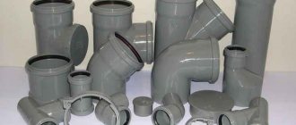
- The entire pipeline connected to the central manifold;
- Central sewer riser.
The external test system includes:
- A pipeline placed outside a building to transport wastewater to a point of accumulation or disposal;
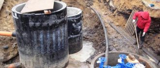
- All inspection and rotary wells;
- Storm drainage channels.
In order for the testing to pass efficiently and fully reflect the condition and performance of the sewer communication, it is necessary to adhere to the basic rules:
Thus, all plumbing points must be cleared of possible construction and natural debris before carrying out work; It is worth checking all points for cracks, chips and other damage; It is important to monitor the evenness of all straight sections of the network. There should be no deflections or bends; All vertical risers must be checked using a plumb line; To check the pipeline, you can use either a hydraulic method (spill method) or a pneumatic method (pumping the system with air); Important: drainage of sewer lines can only be carried out if the air temperature around does not fall below +5 degrees
If the outside temperature is below the specified parameter, then a pneumatic testing method is used. It is worth conducting a separate communication check for each floor of the building. To do this, audit plugs are installed on all other floors.
After completing the installation work of internal sewerage systems and drains, the installation organization must carry out their tests and draw up a report in accordance with Appendix “D” “Internal sanitary systems of the building” (updated edition of SNiP 3.05.01-85). These tests must be carried out by pouring water by simultaneously opening 75% of the sanitary fixtures connected to the area being tested. The test method gives rise to the “everyday” name of the act – sewer spill act or sewer spill act. However, the name of the act, according to the regulatory documentation, is as follows: an act of testing internal sewerage and drainage systems
.
We have figured out the correct name of the act and its purpose. Now let’s take a closer look at the form of the test report for internal sewerage and drainage systems and the method of filling it.
First, fill in the name of the system on which the tests were carried out. We take the name of the system from the design documentation. For example, this could be “domestic sewerage K1”.
Next, you need to fill in the name of the capital construction project. There is nothing complicated here. We take information about the name from the design documentation or construction permit. After this, we enter information about the city in which the capital construction project is located and the date of the tests.
The block in which data about the commission that conducted the tests is entered includes the following information: the name of the customer’s organizations, the general contractor, the installation (construction) organization, as well as the positions, initials and surnames of representatives of these organizations.
In paragraph 1 of the test report for internal sewerage and drainage systems, data (name) is entered on the design organization, design documentation code, drawing numbers in accordance with which installation work was performed.
In paragraph 2 we indicate the number of simultaneously open sanitary fixtures and the time during which the tests were carried out. Sanitary fixtures include bathtubs, washbasins, shower trays, drains, bidets, toilets, closet bowls, urinals, sinks, sinks, and drains. During tests in accordance with the rules, at least 75% of the sanitary fixtures connected to the tested area must be open simultaneously.
Clause 3 of the sewerage testing report includes data on defects identified during testing. If no defects are found, then we make a note that during inspection during testing, no leaks were found through the walls of the pipelines and joints.
Based on the results of the tests, a decision is made by the commission, which is recorded in the end of the act. As a rule, this is a template paragraph, which is only supplemented with data about the name of the tested system.
After completion of the tests, the act of spilling is signed by all members of the commission. Changing the form of the act or deviating from it is not allowed.
The quality of installed sewage systems in a country house and beyond is checked at all levels. First of all, all building codes and requirements must be observed. Then the installation is supervised. And at the end, tests are carried out and a sewerage spill report is drawn up, a sample of which can be found on the Internet.
Fire test reports
During testing for the performance and safe operation of fire equipment, several reports are drawn up:
- checking fire hydrants;
- diagnostics of internal water supply;
- checking for the safety of use and compliance with labor protection rules of fire escapes.
Fire hydrants
Testing the performance of hydrants for water loss is carried out twice a year and is often combined with checking the fire-fighting water supply system. Based on the results of the inspection, an act is drawn up and signed by the commission. Mandatory members: a representative of the fire inspection and a representative from the organization in which the inspection is taking place. Also, the commission may consist entirely of company employees.
The act states:
- general organizational information (information about the company, date and place of compilation);
- the main part describes the members of the commission and the progress of the test. Information about hydrants is presented in tabular form. The location address, diameter, pressure, water yield and affiliation of the hydrant are indicated;
- in the final part, compliance (or non-compliance) with the requirements of the hydrant condition is established.
At the end, the act is signed by authorized members of the commission.
Internal fire water supply
The act establishes the presence or absence of defects and malfunctions in the fire water supply system. The inspection is carried out by responsible employees of the enterprise. Frequency – at least twice a year; for flammable industries, inspections may be scheduled more often.
Internal fire water supply (IFP) is a complex system of pipes, sensors, and switches. Therefore, it is often checked by a labor protection or fire safety specialist, as well as by persons who are trained in fire safety.
The act is drawn up on letterhead or plain paper indicating the details. Be sure to register:
- information about the organization and participants of the inspection;
- information about the object being checked;
- inspection results;
- recommendations for eliminating defects and malfunctions, if any are found;
- signatures of responsible persons.
If additional documents are attached to the act, their list and name are indicated.
Fire escapes
Testing of firefighting equipment, including ladders and stepladders, is regulated by a special GOST. Inspections can be carried out by organizations that have received permission from the Ministry of Emergency Situations and have special equipment for this.
The test results are recorded in the test report. The documentation provides standard information about the organization and its details, information about the members of the commission. The main part provides information about the inspected objects (number of ladders and stepladders, their inventory numbers and affiliation with the structural unit), information about the results of inspections (absence or presence of defects). An instruction is given to eliminate the identified faults.
At the end, the act is signed by the members of the commission.
Persons - members of the commission
In a separate paragraph in the inspection report for external or internal sewerage, it is necessary to record all the data about the members of the commission. These are:
- Representatives from the customer organization.
- Representatives from the general contractor. These persons are responsible for the correct installation of drains in case they do not comply with technical and operational standards during a spill.
- Members of the design organization who were involved in the development of the communication project being tested.
- A representative of a company or organization that was engaged in soil research at the site for the installation of external or internal communications. This office bears full responsibility for the inconsistency of the data received on the site regarding environmental and climatic conditions for the construction of sewer communications.
Thus, in the paragraph of the test acceptance certificate, it is necessary to include all the initials and surnames of the commission members with their signatures.
Parties involved in the review
If we are talking about more or less large-scale construction, where several organizations are involved, not counting the customer, tests of sewer systems are carried out by all of them, after which the results are documented in the appropriate inspection report.
Typically, inspection of the sewerage system involves:
- the organization that compiled the project and is responsible for the correctness of calculations and selection of materials and components;
- a company that analyzed climatic and soil conditions and made recommendations for the design of the external components of the sewer system;
- a contractor who was directly involved in installation work related to the laying of internal and external sewer networks and is responsible for compliance of the activities carried out with the project and existing requirements specified in SNiP;
- a customer who controls the correct testing of discharge pipes, connections and some functional units of the sewer network inside the building and in the external section of the wastewater disposal system.
Each of the representatives of the parties participating in the tests and signing the final inspection report is responsible for inaccuracies and shortcomings that arose during testing of sections of the system, individual nodes or the entire network as a whole.
How to test a finished sewerage system
The test method gives rise to the “everyday” name of the act – sewer spill act or sewer spill act. However, the name of the act, according to the regulatory documentation, is the following: act of testing internal sewerage and drainage systems.
Info
We have figured out the correct name of the act and its purpose. Now let’s take a closer look at the form of the test report for internal sewerage and drainage systems and the method of filling it
Attention
Next, you need to fill in the name of the capital construction project. There's nothing complicated here
We take information about the name from the design documentation or construction permit.
Testing of external sewerage networks
Preliminary tests Acceptance tests Pneumatic tests Preliminary tests Hydrostatic pressure in the pipeline during its preliminary testing must be created by filling the riser installed at its upper point with water, or by filling the upper well with water, if the latter is to be tested. In this case, the value of hydrostatic pressure at the top point of the pipeline is determined by the amount of excess of the water level in the riser or well above the pipeline shelyga or above the groundwater horizon, if the latter is located above the shelyga. The magnitude of hydrostatic pressure in the pipeline during testing must be indicated in the working documentation. For pipelines laid from free-flow concrete, reinforced concrete and ceramic pipes, this value, as a rule, should be equal to 0.04 MPa (0.4 kgf/cm2).
Testing of external network Testing of external sewerage is carried out mainly by hydraulic method. Work performed:
- pipeline slope control;
- the pipeline is tested for leaks;
- examination of wells and other equipment.
The slope level of the external sewer is checked by level.
The test is carried out between wells, in stages, each section is disconnected from the system using a plug. Test scheme for non-pressure systems::
- checking pipes for blockages and debris from construction, and flushing if necessary;
- spill test - a section of the system is filled with water; if no leaks are detected within 10 minutes, the test is passed.
Water is supplied to the pressure sewer under pressure. If the pressure at the inlet and outlet of the pipe is the same, the test is also considered passed.
The check includes:
- testing the pipeline for leaks (carried out as described above. For testing, sections of pipes located between wells or other elements of the system are taken);
- checking the pipeline slope level;
- testing of wells and other equipment;
- checking the performance of storm drains.
A level is used to check the level of pipe laying required for a gravity sewer system.
If a pressure sewer test is being carried out, then water must be supplied to the pipeline system at the pressure specified in the design documents. The test of pressure sewerage pipelines is considered successful if the pressure value in the flow into the network and at the exit from it is the same.
As-built documentation
Hydraulic testing of industrial and rainwater sewerage pipelines. Composition and order of work.
The industrial rainwater drainage pipeline must be tested for leaks twice:
- preliminary test - before backfilling and
- acceptance (final) test - after backfilling.
External sewerage networks are tested in sections between adjacent wells or risers with water filling the upper well or riser.
Hydrostatic pressure in the pipeline during its preliminary testing must be created by filling the riser installed at its highest point with water, or by filling the upper well with water, if the latter is to be tested. In this case, the value of hydrostatic pressure at the top point of the pipeline is determined by the amount of excess of the water level in the riser or well above the pipeline shelyga or above the groundwater horizon, if the latter is located above the shelyga.
A preliminary leak test of the pipeline is carried out with the pipeline not covered with earth for 30 minutes. The test pressure value (Rip = 0.04 MPa) must be maintained by adding water to the riser or well, not allowing the water level in them to decrease by more than 20 cm
The pipeline is considered to have passed the preliminary test if no water leaks are detected during inspection. In the absence of increased requirements for pipeline tightness in the project, sweating is allowed on the surface of pipes and joints with the formation of droplets that do not merge into one stream when the amount of sweating occurs on no more than 5% of the pipes in the test area.
After carrying out hydraulic tests, flush and clean the water supply pipelines.
After cleaning and washing, the pipeline must be disinfected by chlorination at a concentration of active chlorine of 75 - 100 mg/l (g/cubic meter) with a contact time of chlorine water in the pipeline of 5 - 6 hours or at a concentration of 40 - 50 mg/l (g/cubic meter). m) with a contact time of at least 24 hours. The concentration of active chlorine is prescribed depending on the degree of contamination of the pipeline.
Drainage system
Testing of internal sewerage and drainage systems must be carried out by pouring water by simultaneously opening 75% of the sanitary fixtures connected to the area being tested for the time required for its inspection.
The system is considered to have passed the test if, during its inspection, no leaks were detected through the walls of the pipelines and joints.
Tests of sewer outlet pipelines laid in the ground or underground channels must be carried out before they are closed by filling them with water to the level of the ground floor floor.
Tests of sections of sewerage systems hidden during subsequent work must be carried out by pouring water before they are closed, with the drawing up of an inspection report for hidden work in accordance with Appendix B.
Internal drains should be tested by filling them with water to the level of the highest drain funnel. The duration of the test must be at least 10 minutes.
Drains are considered to have passed the test if no leaks are found during inspection and the water level in the risers has not decreased.
Cleaning the cavity of pipeline sections before testing must first be cleared of scale and burr, as well as of soil and various objects that accidentally got inside the pipeline during construction.
Cleaning the cavity and flushing the pipeline to remove remaining contaminants and random objects should be performed, as a rule, before conducting a hydraulic test by water-air (hydropneumatic) flushing or hydromechanically using elastic cleaning pistons (foam rubber and others) or only with water.
Tests of non-pressure sections of pipelines should be tested for leaks twice:
-preliminary (before backfilling)
- acceptance-final (after backfilling)
Leak tests:
a) determining the volume of water added to a pipeline laid in dry soils, as well as in wet soils, when the groundwater level at the top well is located below the surface of the earth by more than half the depth of the pipes, counting from the hatch to the shelyga;
b) determining the influx of water into a pipeline laid in wet soils, when the groundwater level at the upper well is located below the surface of the earth by less than half the depth of the pipes, counting from the hatch to the shell.
Wells of free-flow pipelines that are waterproofed on the outside should be tested for leaks by determining the flow of water into them.
Non-pressure pipelines should be tested for leaks in areas between adjacent wells.
Hydrostatic pressure in the pipeline during its preliminary testing should be created by filling the upper well with water, if the latter is to be tested.
In this case, the value of hydrostatic pressure at the top point of the pipeline is determined by the amount of excess of the water level in the well above the pipeline shell.
Preliminary testing of pipelines for leaks is carried out with the pipeline not covered with earth for 30 minutes. The test pressure must be maintained by adding water to the well, without allowing the water level in it to drop by more than 20 cm.
The pipeline and well are considered to have passed the preliminary test if no water leaks are detected during their inspection. On the surface of pipes and joints, sweating is allowed with the formation of drops that do not merge into one stream when the amount of sweating occurs on no more than 5% of the pipes in the test area.
Acceptance testing for tightness should begin after keeping pipelines and wells in a water-filled state for 24 hours.
Tightness during acceptance testing of a buried pipeline is determined by the following methods:
- first - based on the volume of water added to the well measured in the upper well for 30 minutes; in this case, a decrease in the water level in the well is allowed by no more than 20 cm;
- the second - based on the volume of groundwater flowing into the pipeline measured in the lower well.
The pipeline is recognized as having passed the acceptance test for leaks if the volumes of added water determined during testing using the first method (groundwater influx using the second method) are no more than those indicated in the table. 8, SNiP 3.05.04-85*. about which an act should be drawn up in the form of mandatory Appendix 4, SNiP 3.05.04-85*.
You may be interested in: “What elevations should be indicated on diagrams and plans”
Notes:
- When the test duration increases beyond 30 minutes, the permissible volume of added water (water influx) should be increased in proportion to the increase in test duration.
- The permissible volume of added water (water inflow) into a reinforced concrete pipeline with a diameter of over 600 mm should be determined by the formula
q = 0.83 (D +4), l, per 10 m of pipeline length during the test, 30 min, (2)
where D is the internal (conditional) diameter of the pipeline, dm.
- For reinforced concrete pipelines with butt joints on rubber seals, the permissible volume of added water (water influx) should be taken with a coefficient of 0.7.
- The permissible volumes of added water (water inflow) through the walls and bottom of the well per 1 m of its depth should be taken equal to the permissible volume of added water (water influx) per 1 m length of pipes, the diameter of which is equal in area to the internal diameter of the well.
- The permissible volume of added water (water influx) into a pipeline constructed from prefabricated reinforced concrete elements and blocks should be taken the same as for pipelines made from reinforced concrete pipes of equal cross-sectional area.
- The permissible volume of water added to the pipeline (water influx) per 10 m of the length of the tested pipeline during a test of 30 minutes for LDPE and HDPE pipes with welded joints and PVC pressure pipes with adhesive joints should be determined for diameters up to 500 mm inclusive. according to the formula q = 0.03D, with a diameter of more than 500 mm - according to the formula q = 0.2+0.03D, where D is the outer diameter of the pipeline, dm; q is the permissible volume of added water, l.
- The permissible volume of water added to the pipeline (water influx) per 10 m of the length of the tested pipeline during a test of 30 minutes for PVC pipes with connections on a rubber cuff should be determined by the formula q = 0.06 + 0.01D, where D is the outer diameter of the pipeline, dm; q is the permissible volume of added water, l.
Cast iron testing
If there is no indication in the project about the testing method, pressure pipelines are subject to testing for strength and tightness, as a rule, by hydraulic method. Depending on the climatic conditions in the construction area and in the absence of water, a pneumatic testing method can be used for pipelines with an internal design pressure Рр, not more than:
underground cast iron, asbestos-cement and reinforced concrete - 0.5 MPa (5 kgf/cm2);
underground steel - 1.6 MPa (16 kgf/cm2);
above-ground steel - 0.3 MPa (3 kgf/cm2).
Testing of pressure pipelines of all classes must be carried out by a construction and installation organization, as a rule, in two stages:
the first is a preliminary test for strength and tightness, carried out after filling the sinuses with tamping soil to half the vertical diameter and powdering the pipes in accordance with the requirements of SNiP 3.02.01-87 with butt joints left open for inspection; this test can be carried out without the participation of representatives of the customer and the operating organization with the drawing up of a report approved by the chief engineer of the construction organization;
the second - acceptance (final) test for strength and tightness should be performed after the pipeline is completely backfilled with the participation of representatives of the customer and the operating organization with the drawing up of a report on the test results in the form of mandatory annexes.
Both stages of the test must be performed before installing hydrants, plungers, and safety valves, in place of which flange plugs should be installed during the test. Preliminary testing of pipelines that are accessible for inspection in working condition or that are subject to immediate backfilling during the construction process (work in winter, in cramped conditions), with appropriate justification in the projects, may not be carried out.
Pipelines of underwater crossings are subject to preliminary testing twice: on a slipway or platform after welding the pipes, but before applying anti-corrosion insulation to the welded joints, and again - after laying the pipeline in a trench in the design position, but before backfilling with soil.
The values of the internal design pressure РР and test pressure Рi for carrying out preliminary and acceptance tests of the pressure pipeline for strength must be determined by the project in accordance with the requirements of SNiP 2.04.02-84 and indicated in the working documentation.
The value of the test pressure for tightness Pg for carrying out both preliminary and acceptance tests of the pressure pipeline must be equal to the value of the internal design pressure Pp plus the value P taken in accordance with Table. 4 depending on the upper limit of pressure measurement, accuracy class and scale division of the pressure gauge. In this case, the value of Pr should not exceed the value of the acceptance test pressure of the pipeline for strength Pi.
Pipelines made of cast iron pipes, regardless of the testing method, should be tested with a length of less than 1 km - in one step; for longer lengths - in sections of no more than 1 km. The length of the test sections of these pipelines using the hydraulic testing method is allowed to exceed 1 km, provided that the permissible flow rate of pumped water should be determined as for a section 1 km long.
Inspection of the pipeline in order to identify defective areas is allowed to be carried out when the pressure is reduced: in cast iron - up to 0.1 MPa (1 kgf/cm2). In this case, leaks and other defects in the pipeline should be identified by the sound of leaking air and by bubbles formed in places of air leaks through butt joints coated on the outside with soap emulsion.
Defects identified and noted during pipeline inspection should be eliminated after the excess pressure in the pipeline has been reduced to zero. After eliminating the defects, the pipeline must be retested.
The pipeline is recognized as having passed the preliminary pneumatic strength test if a thorough inspection of the pipeline does not reveal any violation of the integrity of the pipeline or defects in joints and welded joints.
The pipeline is tested under pressure for the time specified in table. 7:
Well testing
Wells of non-pressure pipelines that are waterproofed on the inside should be tested for tightness by determining the volume of added water, and wells that are waterproofed on the outside should be tested by determining the flow of water into them.
Wells that are designed to have waterproof walls, internal and external insulation, can be tested for the addition of water or the influx of groundwater, in accordance with clause 7.22, together with pipelines or separately from them.
Wells that do not have waterproof walls or internal or external waterproofing according to the design are not subject to acceptance testing for tightness.
During its preliminary testing, hydrostatic pressure should be created by filling a well installed at the top point of the well with water. In this case, the value of hydrostatic pressure at the top point is determined by the excess of the water level in the well above the shelyga or above the groundwater horizon, if the latter is located above the shelyga. The magnitude of hydrostatic pressure during its testing must be indicated in the working documentation.
The test pressure must be maintained by adding water to the well, without allowing the water level in them to drop by more than 20 cm.
The well is considered to have passed the preliminary test if no water leaks are detected during its inspection. In the absence of increased requirements for surface tightness in the project, fogging with the formation of droplets that do not merge into one stream is allowed when the amount of fogging is no more than 5% in the test area.
Hydraulic tests at negative temperatures:
- Hydraulic testing at subzero air or ground temperatures is permitted only if the pipeline, fittings and technological equipment are protected from freezing and compliance with safety, labor and environmental requirements.
- In conditions of negative temperatures, possible limitations in the application of the test method should be taken into account:
- water testing - seasonal lack of water (freezing of rivers, lakes, etc.), environmental protection requirements when draining water from the pipeline, thermal test parameters;
- air testing - the specifics of operating mobile compressor units at low outside temperatures;
- the temperature of the pipeline walls during strength testing and leak testing is limited by the cold resistance temperature of the pipe material.
- Hydrotests at subzero temperatures have specific features due to the increasing role of the time factor. Therefore, when carrying out such tests it is necessary:
- complete them within a time strictly determined by the calculation, during which freezing of water in the pipeline is prevented;
- ensure mandatory monitoring of the temperature of the liquid (water with added salt) in the pipeline and assessment of pressure changes when testing for leaks, taking into account temperature changes;
- covering and insulation of the pipeline, its open parts, fittings, connection points for units and devices;
- clean the cavity by blowing, pulling, or combine cleaning the cavity with removing liquid after hydrotesting;
- install piston receiving units, eliminating the filling of the pipeline with water at the open end, draining water by gravity and other uncontrolled processes of water movement in the pipeline;
- ensure that liquid can be removed immediately from the pipeline, which is ensured by having gas or air sources available and connecting them to both ends of the test sections prior to testing.
- Tests are carried out with heated water, with constant monitoring of the water temperature to prevent freezing.
- In order to increase the reliability of testing in winter conditions, before filling with water, perform the following measures:
- thorough backfilling of the underground and embankment of the above-ground pipeline along its entire length;
- applying thermal insulation (mineral wool, etc.) to the above-ground pipeline and additional insulation of the places where the pipeline is laid on supports;
- insulation and covering of fittings, piston launching and receiving units, drain pipes and other open parts of the pipeline being tested;
- insulation and covering of connection points for filling and pressure testing units, piping pipelines with fittings;
- work on connecting connection points to a source of gas or air used to remove water from the pipeline.
- It is necessary to strive to ensure that the water in the pipeline during the preparation of the test is in a static state for as little time as possible.
- If delays occur in the production of testing work, leading to the exceeding of the test time accepted in the calculation, pumping water at a temperature determined by calculation through the test area should be resumed. It is allowed to pump water during the period between strength and tightness tests, as well as during the period when the pipeline is not under test pressure.
- When preparing for a hydraulic test in the winter-spring period, in order to prevent water from freezing during a sudden cold snap, it is necessary to carefully monitor the backfilling or embankment of the pipeline along its entire length. Particular attention should be paid to ensuring that the fittings and connection points are carefully covered.
- After the snow falls, it is necessary to further insulate the pipeline by embanking it with snow, keeping in mind that the thermal insulation properties of a 20 cm thick layer of snow are equivalent to approximately 100 cm of soil.
- Hydraulic testing with water at negative air temperatures is permitted subject to the following measures to maintain a positive water temperature in the pipeline:
- — organization of temperature control with an electronic thermometer of water in the pipeline during testing;
- — protection of above-ground parts of the pipeline, fittings and instruments from freezing, insulation and covering of connection points for filling and pressure testing units, chambers for launching and receiving SOD, drain pipes and piping pipelines with fittings with heat-insulating materials (mineral wool, winding);
- — protect measuring instruments, the recorder and their connections to the pipeline from freezing with thermal insulation wrapping material (mineral wool, wrapped in plastic film)
- — additional embankment of laid pipelines with soil and (or) snow;
- — completion of tests within a time strictly determined by calculation, during which freezing of the liquid in the pipeline is prevented;
- — measures for emergency emptying of the pipeline in the event of a threat of water freezing, by relieving pressure to 0 MPa and purging the pipeline with compressed air from compressors.
Testing with liquids with a low freezing point
- Testing of pipelines at subzero temperatures should be performed using water with added salt.
- Pipeline testing must be planned so that during the period of this work the temperature inside the pipeline does not decrease (for example, due to a decrease in the outside air temperature) to the freezing temperature of the test liquid.
- If a pipeline ruptures, it is necessary to promptly localize the area where the test liquid is released using dams, embankment with soil, followed by neutralization.
- The possible test period is determined from the condition that the freezing temperature of water must be below the minimum temperature of the backfill soil (for underground installation) or the outside air temperature (for above-ground installation) during the test.
Additional requirements for testing pressure pipelines and water supply and sewerage structures built in special natural and climatic conditions
Pressure pipelines for water supply and sewerage, constructed in conditions of subsidence soils of all types outside the territory of industrial sites and populated areas, are tested in sections no longer than 500 m; on the territory of industrial sites and populated areas, the length of test sections should be determined taking into account local conditions, but not more than 300 m.
Checking the water resistance of tank structures built on subsidence soils of all types should be carried out 5 days after they are filled with water, and the loss of water per day should not exceed 2 liters per 1 m2 of the wetted surface of the walls and bottom.
If a leak is detected, water from the structures must be released and diverted to places determined by the project, excluding flooding of the built-up area.
Hydraulic testing of pipelines and tank structures constructed in areas of permafrost soils should be carried out, as a rule, at an outside air temperature of at least 0 ° C, unless other test conditions are justified by the design.
See the composition of the executive in the section: “Composition of the executive”
Download acts, protocols and more in the section: “Acts and other”
Download useful books, GOSTs, SNIPs in the section: “GOSTs and books“
Who is responsible for the functionality of the sewer system?
The commission inspecting the sewer network includes representatives of:
- the company that made up . This organization is responsible for the correctness of calculations and drawing up drawings of the sewerage network;
- organization that carried out research in the area where sewerage installation was planned. This company is responsible for the accuracy of the data regarding climatic conditions and environmental conditions on the basis of which the system design was developed;
- companies involved in laying sewer networks are responsible for the quality of work and compliance with existing standards;
- customer organization. Controls all stages of construction. Responsible for the correctness of the inspection when putting the sewer network into operation.
Each organization has its own area of responsibility, the boundaries of which are clearly defined. After the inspection, all members of the commission sign a test report for the sewerage system.
If errors or shortcomings are discovered, each company may be subject to criminal, disciplinary or administrative liability.
Test reports: download a blank form and sample filling
Document year: 2019
Type of document: Act
Download formats: DOC, PDF
Test reports are drawn up in the form of document forms in which the results of testing the performance of mechanisms and equipment are recorded.
In today's article, we will consider in detail the testing of pipeline systems, sewerage systems, stairs and stepladders, roof fencing and fire tests.
Examples of drafting acts can be downloaded for free at the end of the article.
Testing basic principles
The internal system includes the following objects:
- All plumbing points and household appliances that drain water;
- The entire pipeline connected to the central manifold;
- Central sewer riser.
The external test system includes:
- A pipeline placed outside a building to transport wastewater to a point of accumulation or disposal;
- All inspection and rotary wells;
- Storm drainage channels.
In order for the testing to pass efficiently and fully reflect the condition and performance of the sewer communication, it is necessary to adhere to the basic rules:
Thus, all plumbing points must be cleared of possible construction and natural debris before carrying out work; It is worth checking all points for cracks, chips and other damage; It is important to monitor the evenness of all straight sections of the network. There should be no deflections or bends; All vertical risers must be checked using a plumb line; To check the pipeline, you can use either a hydraulic method (spill method) or a pneumatic method (pumping the system with air); Important: drainage of sewer lines can only be carried out if the air temperature around does not fall below +5 degrees
If the outside temperature is below the specified parameter, then a pneumatic testing method is used. It is worth conducting a separate communication check for each floor of the building. To do this, audit plugs are installed on all other floors.
During testing of external sewerage using the spill method, the same document is drawn up as during testing of the internal sewage system. The form of the act itself is not a form of strict reporting and can be drawn up by the customer, contractor or subcontractor.
Also, during experiments on an external water drainage system, one of the forms of SNiP 3.05.04-85 can be used, which is a general form of document for acceptance of work performed when installing or repairing a drainage system.
Consequences of violation of systematic testing
If you do not check the operation of the new highway and do not fill out a test report, then the regulatory authorities will not allow this facility to be put into operation. If testing deadlines for an existing pipeline are not met, this may lead to breakdown of the entire system and bring even greater losses. Only during system checks under pressure can minor problems be seen in the form of leaks at the joints. Leaks can lead to pipe repairs and shutdown of the entire network.
During the installation of modern networks, which have an operational life of more than fifty years, one test can be carried out upon completion of installation or repair work. In Russia, almost all central highways were installed many decades ago, and therefore require constant inspection. These measures will allow timely repair of communications or complete replacement of structural elements.
Filling out the act point by point
- Paragraph 1 will contain detailed information about the company that designed the drainage system. The name of the code in which all project documentation was compiled is also included here. In addition, in the first paragraph of the document on testing the sewage system by pouring internal and external communications, it is necessary to enter all the numbers of the drawings that were used during installation for each drainage section.
- Clause 2 of the above-mentioned test report must contain accurate information about the number of simultaneously open sanitary points and the period of time during which the tests took place using the full pressure flow method. According to SNiP, sanitary points include toilets, sinks, bathtubs, showers, bidets, urinals, drains, etc.
- Clause 3 of the completed report is intended for records of possible violations in the operation of the system. That is, about the occurrence of leaks, stagnation, blockages, etc. If this was not detected at the time of checking the communication, then in paragraph 3 an entry is made that no leaks or other unauthorized deviations in the operation of the sewer system were detected at the time of the test.
- The last section is the decision of the commission, which allows or does not allow the drain to be put into operation depending on the test result obtained.
If obvious deficiencies are found in the communication work, indicating the negligent attitude of the contractor or all organizations accompanying his work, then the organization responsible for the deficiency, according to the law, bears administrative, disciplinary or criminal liability (depending on the identified defect).
Certificate of testing of external and internal sewerage for spillage
A test report for internal and external sewerage is drawn up as a result of checking the operability of the system. It confirms the position of the commission that the system has withstood the test of a spill of water, and the design complies with the design documentation, GOSTs and standards.
Diagnostics of the normal functionality of the sewer system is necessary when installing a new facility or after carrying out repair work on an existing system. Information about the performance check is entered into the report. The form is drawn up in the form specified in Appendix “D” to the Code of Rules 73.13330.2012.
The act specifies:
- name of the system and the facility in which it is installed;
- information about the members of the commission. Representatives of three organizations are needed: the general contractor, the customer and the installation company;
- information about the name of the project is written down;
- the results are entered: the number of simultaneously connected devices, as well as the connection time or filling of water on the floor (unnecessary ones are crossed out);
- the third paragraph states that no leaks were detected at the joints and through the walls. This means the system is suitable for use.
The decision is signed by the members of the commission.
Specifics of drawing up a test report
Regardless of the type and method of verification, the document must contain the following points:
The header of the document, which should indicate the date of preparation and the city in which the document is drawn up and signed. Indication of the city is mandatory, since the signing of the act may occur outside the locality where the installation or repair of the water drainage system was carried out.
Also in this part of the document the name of the organizations and the full name of the managers must be indicated, as in the charter of the organizations that carried out control, testing and technical or designer supervision of the progress of work.
Also in this paragraph there should be footnotes on the design marks and coordinates of the sewage system, in accordance with the general plan or special sections of the construction project.
Sample of filling out the document header
After the header of the document there is an extract from the technical conditions according to which the experiments were carried out. This section contains calculation formulas, a list of necessary test equipment, conditions and procedures for carrying out work.
When filling out this item, data taken from measuring instruments during research are used. If the act itself does not contain this section, then there should be a link to the test report, which describes the process in detail and all calculations are made. All results can be summarized for convenience in a single table.
Sample of filling out the measurements and calculations section
The last item is the decision of the commission, which indicates the result of the tests and the conclusion that the drain system is ready to be accepted into operation. In case of discrepancy, the reason is indicated and links to defective statements and acts for correction and revision are provided.
If the pipeline has passed all tests, the full data of all members of the acceptance committee and their signatures are indicated, after which this document becomes the basis for drawing up a statement of disagreements or a statement of work performed, according to the conclusion of the expert commission.
An important condition for the preparation of this document is the procedure for vesting powers in the members of the commission, for which the necessary orders of managers must be created. Also important are the certification documents of all members of this commission, confirming the qualifications of the participants to conduct research or monitor the progress of its implementation.
Paper rules
Based on the general requirements of the current regulations, each paragraph of the act must be completed. As soon as the final list of responsible persons is formed and filled out, you can begin to draw up the remaining points of the document.
Act
In order to avoid mistakes and omissions in the act, it is worth remembering all the details in each paragraph:
- First point. This part of the paper contains information about the name of the company that developed and approved the house project. The document compliance code is also written down here, and the serial numbers of the revision of all components of the drainage system based on the working design are listed. In addition, it is necessary to list the working numbers of the drawings used for the drainage system in a specific type of building.
- Second point. This part of the document contains exact values for the number of all simultaneously open visible sanitary points. The time periods during which the checks were carried out are listed. Sanitary points can be all plumbing fixtures that a person uses in everyday activities (toilet, sink, shower, bidet, and so on). It is important to remember that filling out the second paragraph implies hydraulic testing of the sewer system when working at least three quarters of the total number of sanitary points.
- Third point. The violations and inconsistencies identified during the inspection stage are listed. Here it is important to indicate all the comments that the commission had during the testing process with a detailed description of the problem. If there are no deficiencies, “not identified” is written in the column.
- Conclusion. This part of the act contains the final decision of the commission and the recommendatory part to eliminate the identified shortcomings. The last sentence must indicate whether the system is permitted for operation.
You may also like: All about hydrodynamic drain cleaning
Methods for testing sections of internal sewerage
- testing network pipes for strength and their connections for tightness;
- compliance of the location of installed instruments and elements of the outlet pipeline with the design documentation;
- correct installation of plumbing fixtures in relation to the floor surface (the distance from the floor to the upper edge of the receiver of each plumbing fixture is specified in the above-mentioned SNiP);
- the presence of a slope in the horizontal sections of the pipe and the degree of verticality of the risers.
Testing of pipes and connections for leaks in a gravity system, regardless of the material of the pipeline and fittings, is carried out using the spill method. The essence of the technique is that part of the main pipeline (bed) is fenced off in a certain area from the rest of the system. This is done with special plugs through inspection holes. The separated area is checked by filling it with water through the pipes of plumbing fixtures
According to SNiP, the results of a spill deserve attention if the pipeline was filled with the participation of at least ¾ (or 75%) of all devices connected in a given isolated section. Testing of the pipeline using the spill method is considered positive if the connections after filling the system did not give the slightest leak within 10-15 minutes (depending on the volume of the area filled with water)
According to the regulatory documentation, a spill, that is, testing a sewer system by filling it with water, is informative when the air t˚ is above 5˚. If the temperature is lower, a pneumatic leak test of pipes and connections is carried out (compressed air). The integrity of the riser, sometimes of external sections of the pipeline, is also determined by air. We will use the pneumatic testing method to assess the performance of a pressure sewerage system, when wastewater is forced out, under pressure created by pumping equipment.
The location of installed plumbing fixtures and its compliance with project documentation is determined visually. The height of the receiver of each device, the correct connection of the toilet drain, siphons of the washbasin, bathtub, sink, etc. are objectively assessed and reflected in the report. The condition of the plumbing fixtures themselves is also visually assessed. They must be free of visible dirt and mechanical damage.
The correct slope of the pipes inside and outside the building is controlled using a building bubble level. If the slope of the internal sewer network is allowed to be at least 1 cm per linear meter, then on the outside this figure must be increased to 2 cm per meter.
The installation position of the riser (this data is also reflected in the final report) is checked with a plumb line. A deviation from the vertical of 3˚ is allowed. A water tightness test of the riser is also carried out. The pressure should be about 0.8 MPa.
Testing the internal sewer network
When carrying out test work, it is required to be guided by SNiP “Sewerage. External networks and structures.” According to this document, the following is checked:
- compliance with the developed project;
- testing sewerage pipelines for strength and reliability of joints;
- correctness and reliability of installed devices and flushing elements;
- verticality of mounted risers.
Testing of nodes
Compliance with the design is checked visually. Each element of the system must be located exactly in the place where it is indicated on the plan or drawing.
An example of a layout of devices inside the house
All installed devices must be cleared of debris and thoroughly washed. They should not have visible damage (chips, cracks, etc.) or bending. When installing devices, deflections must not be allowed.
The risers are checked for verticality with a plumb line.
The verticality of the risers is checked with a plumb line
Pipeline testing
Pipeline inspection can be carried out hydraulically or pneumatically.
A hydraulic sewer test involves pumping the system with water, and a pneumatic test with air.
The system can be checked with water if the ambient temperature is not less than 5ºC. In other cases, it is recommended to use the pneumatic method.
If the house has more than one floor, then the system is checked on each of them separately. To temporarily disconnect a floor from the general sewerage system, plugs are used that are inserted into the inspection.
Plugs are used to temporarily disconnect parts of the sewer system.
Pipeline testing is carried out according to the following scheme:
- All pipes are checked for blockages and construction debris. If necessary, they are washed;
Pipe flushing
- Horizontal sections of the pipeline undergo drainage testing. To do this, at least ¾ of all drains are opened. The fenced off section of the sewer system is completely filled with water. If no leaks are detected within 10 minutes of operation, the test is considered passed;
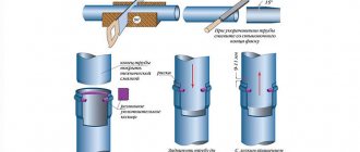
- to check vertical sections of the pipeline, water is supplied under pressure not exceeding 0.08 MPa. The sewerage test for the tightness of pipelines is completed if no leaks or ruptures in the system are detected within 15-20 minutes.
Example of pipe leaks
If one or more sections of pipes are found to be leaking, the problem must be corrected and the test must be carried out again.
After installing the sewer system, before moving on to finishing work inside and backfilling trenches outside, the drainage network must be tested to ensure the tightness of the nodes, pipelines and their connections. The external system and internal network are checked in various ways, regulated by the fundamental document of builders - SNiP. How to test the tightness of pipes and sewer connections by pouring, filling, and other methods, and what data is entered, if necessary, into the inspection report, you will learn by reading the article.
The entire sewerage system in each building is divided into an internal sewage disposal network and an external sewerage system. Internal sewer wiring includes the following components to be checked:
- plumbing fixtures and their connections with outlet pipes;
- local sections of a horizontal pipeline with pipes flowing into it from plumbing fixtures;
- sewer risers;
- outgoing pipe.
In the external part of the sewer system, sections of the pipeline (between cleaning and auxiliary equipment) are tested for leaks, as well as:
- operability of wells, tightness and slope of the pipeline;
- condition of treatment or storage facilities (reservoirs);
- storm sewer.