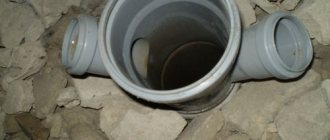
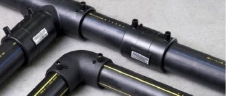
Installation of plastic sewer pipes requires following certain rules. Before assembling the pipeline, you must make sure that the cut edge of the pipe is chamfered and there is an O-ring in the socket.
Clean the sealing ring, the inside of the socket and the chamfered end of the pipe from contamination.
Apply lubricant to the smooth end of the pipe or fitting (silicone-based paste helps maintain the mechanical properties of the rubber seal for a longer time and facilitates disassembly during dismantling).
Installation of plastic sewer pipes
The smooth edge of the pipe or fitting is placed into the socket until it stops, and the contact point between the smooth edge of the pipe and the socket is marked. Then the smooth edge of the pipe must be pulled out of the socket by 10 mm and left there for fixation.
A gap of 10 mm is necessary to compensate for changes in pipe length resulting from thermal expansion. This will avoid the occurrence of internal stresses in the system and, as a result, deformation of the pipes.
The sockets of pipes and fittings, except for double-socket couplings, must be directed against the movement of water.
During installation, the open ends of pipelines and drainage funnels must be temporarily closed with plugs.
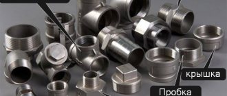
Repair and additional installation of fittings
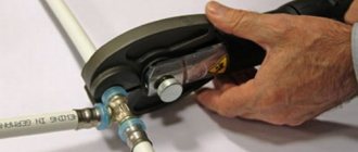
Additional installation (insertion) of fittings into an existing pipeline is possible using push-on (repair) couplings.
Installation procedure:
- cut off a section of pipe (the length of the fitting used plus two outer diameters of the pipe);
- chamfer the cut ends of the pipe;
- place a sliding coupling on one end of the pipe along its entire length;
- place the second sliding coupling on the connecting element;
- install the fitting;
- Insert the connecting element into the remaining gap in the pipeline and close both gaps by moving the slip-on coupling.
Repair using a coupling
Pipe diameter value
The properties of the material determine the scope of application of communications. PP pipes are not always exposed to extreme pressure. In accordance with the value of this parameter, polypropylene products are selected.
For sewerage, it is preferable to use PPR80 type pipes. They meet the requirements for such communications more than others. The main property is resistance to the influence of aggressive environments.
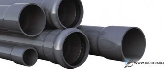
PP pipe range:
- diameter is 50, 100 and 150 mm - common options, used when installing non-pressure pipelines, range of values: from 16 to 2000 mm;
- for pressure communications, the value of the main parameter varies from 32 to 2000 mm.
The length varies from 2 to 8 m. Less often, the value of this parameter reaches 12 m. The step between sizes depends on the type of communications. The pressure version is available in a wider range: the step between sizes is 1″.
The dimensions determine the scope of application of the products, for example, the 50 mm variety is used in residential buildings (when installing internal wiring). Polypropylene sewer pipes 110 mm are installed when installing risers. Larger analogues are used when laying external sewerage.
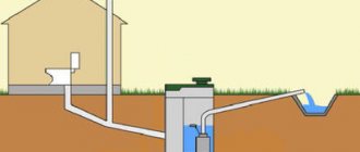
Schematic diagram of internal sewage system made of polypropylene:
Internal sewerage installation diagram
Related article:
Sewer cleaning - methods, options, tools and means. A separate article describes in detail how to independently deal with sewerage blockages in a city apartment and private house. Read it, it might be interesting.
How to care for polypropylene pipes
In terms of caring for PP drainage systems, there are also some subtleties. Like other products, plastic elements need cleaning and prevention so that this unpleasant phenomenon occurs as rarely as possible.
To clean the pipe, products based on alkalis and acids (powder or gel) are mainly used. If there is already water in the drain, then it is best to use a gel that will penetrate to the clogged area without much difficulty. Gels are often made on the basis of acids, so with their help you can easily deal with clogs in the sink or bathroom (that is, where hair or soap deposits most often get stuck).
In the case of the kitchen, powders and granules are the best choice. Thanks to the powerful alkalis contained in the powders, fat is removed very easily.
The resulting blockage can also be removed in an alternative way - using a special plumbing cable. But here you need to be careful with the tool - there should be a springy nozzle at its end, and the working cross-section of the pipe also plays a role. There are also cables with a metal brush at the end, which will deal with the blockage even faster, but will scratch the inner surface of the product. And deposits tend to accumulate faster on the rough walls of used pipes.
Nowadays, this cleaning method is popular when ordinary water is used, which is supplied under high pressure by special hydraulic equipment. Thus, this method is the simplest, and at the same time the most effective.
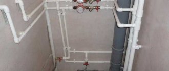
Connection with cast iron pipes
When installing plastic sewer pipes when switching to a cast iron pipe, the socket of the polypropylene pipe is connected to the smooth end of the cast iron pipe using a transition compensation pipe. The inner diameter of the pipe socket corresponds to the outer diameter of the corresponding cast iron pipe. A special set of rubber rings is applied to the smooth end of the cast iron pipe and then the pipe is installed without lubrication.
To connect the smooth end of a plastic pipe to the socket of a cast iron pipe, a set of rubber rings is used, which is applied to the smooth end of the pipe or fitting and inserted into the cast iron socket or transition joint.
Connection with cast iron pipes
What are pipes and what are their features?
Polypropylene sewer pipes are made from PPR 80 copolymer. This material is characterized by chemical resistance to alkaline and acidic solvents. For this reason, such polypropylene pipes are ideal for indoor sewerage.
The material is produced by modernizing the structure of polypropylene. Ethylene molecules are added to the initial composition, which improves the final properties. PPR 80 copolymer, compared to other materials, is more durable, resistant to high temperatures and has a long service life. The described sewer pipes made of polypropylene are mainly used in household and engineering communications.
Important! PPR 80 copolymer is safe for both the environment and human life.
Positive qualities of PP:
- Polypropylene pipes used for sewerage have a long service life. As the manufacturers themselves state, their service life reaches 50 years.
- Sewerage from such polypropylene pipes may not be painted.
- PP sewer pipes are not demanding in terms of insulation. This is explained by the fact that they have low thermal conductivity. In short, there will be no heat loss, and condensation will not accumulate on the outside.
- Compared with other options, PP products can save heat by 20%.
- They provide trouble-free transportation of liquids whose temperature does not exceed +95 degrees Celsius. This is the best option for household pipelines.
- Water pipelines made from polypropylene products are lightweight, so the elements themselves are easier to transport and communications are easier to assemble. Compared to metal utility networks, polypropylene sewage systems weigh 8 times less. This makes installation of products more affordable.
- The material does not allow stray currents to pass through, so electrical insulation is not required.
- Since the material is resistant to chemical influences, the diameter of the elements will always remain the same (throughput).
- There is no bacterial flora, so the free-flow sewer remains hygienic.
- Using polypropylene pipes, sewerage is installed 4 times faster than using other materials.
- A smooth surface is also beneficial, since deposits will not form from the inside during the operation of the sewer system, affecting the permeability of the liquid.
- Chemical reagents and aggressive environments are not harmful to PP.
- Due to the excellent sound insulation, you will not hear water moving through the products.
- PP elements are not capable of changing the composition of the liquid passing through them.
- Lower flow resistance, since the inside of the products is absolutely smooth.
We recommend that you read: Water inlet for polypropylene pipes and its use in water supply systems
Transportation
Transportation, loading and unloading of pipes and fittings made of polypropylene must be carried out at a temperature not lower than minus 10°C. Transportation at lower temperatures is only permitted if special devices are used to secure the pipes, and special precautions are taken when loading and unloading.
Pipes and fittings made of polypropylene should be protected from impacts and mechanical loads, and their surfaces should be protected from scratches. When transporting pipes, they must be laid on a flat surface of the vehicle, protected from sharp metal corners and platform edges.
How polypropylene pipes are installed
It is not difficult to install polypropylene products, which even a novice master can handle, for example, if he needs to connect a septic tank. During the installation process, no special tools or equipment are required.
Most often, the “socket” connection method is used, where the work looks like this:
- Laying is horizontal. Before starting work, you should check the elements for integrity and whether the gasket complies with the project;
- The junction of the products is the socket, which should be thoroughly cleaned and all dust and dirt removed from the surface. Check to see if there is a rubber seal in the socket;
- The depth of entry of the element into the prepared socket is measured. A mark is placed to indicate where the product will go all the way;
- Silicone grease is used to lubricate the products, after which the product is inserted into the socket until it stops. After this, starting from the pre-made mark, you should pull out the pipe 1 cm, which is easy to do with your own hands.
We recommend that you read: How to choose and correctly use glue for polypropylene?
When connecting PP, the use of welding is also relevant. To connect pipes, it is necessary to use a special welding machine, with the help of which the ends of the products are heated to the temperature until they begin to melt.
The steps are as follows:
- Before starting work, you need to prepare everything: take fittings, pipes, cut them into the required lengths. It is important to ensure that the cutting element is sharpened to avoid damage to the material.
- If there are burrs on the surface of the product, they are removed with sandpaper. If a reinforced part is used, you must first remove the top layer of foil.
- Each prepared part must be thoroughly degreased.
- Each welding machine comes with instructions that indicate the holding time during heating.
- You need to connect the heated parts slowly and carefully. It is better not to rotate the parts during the joining process, otherwise sagging will form, which will ultimately reduce the working cross-section of the pipe.
After inserting the product, the heated area cools down and the result is a monolithic connection. This method is relevant for sewerage networks, both internal and external.
It is important to understand that the sizes of pipes for external and internal networks are different.
Installation of internal networks
Polypropylene for internal sewerage
The process takes a lot of time, even with careful attention to each step.
Without following a certain sequence, it will not be possible to achieve the desired result.
As well as without thoroughness and accuracy.
The performance of the entire system depends on how competently the work is carried out.
Professional help is irreplaceable, although it is possible to carry out some of the work yourself.
The mandatory document for review will be SNiP “Internal water supply and sewerage”.
Even if you prepare the project yourself, it is recommended to show the latter to a specialist. Then there is less chance of problems occurring in the future. Only after approval can you begin purchasing the required materials.
Sewage systems and their ventilation
To organize ventilation, you need to install special risers. They all go through the roof. Not a single drainage riser can do without ventilation devices. The system itself is needed to solve three different problems:
- Reducing extraneous noise.
- Maintains pressure at a constant level.
- Getting rid of odor.
The ventilation pipe must have the same diameter as the riser. Or bigger. The exhaust part of the structure cannot be combined with the chimney and ventilation system.
When draining water, the air becomes rarefied if there is no ventilation in the system. Because of this, unpleasant odors appear indoors.
SNiPs also describe in detail what the height of ventilation above the roof should be.
- 3 meters - above the roof in use.
- 0.5 meters - for a pitched roof.
- 0.3 meters - for a flat roof that is not actively used.
The distance to the prefabricated ventilation shaft must be at least 0.1 meters.
External sewerage networks. About the basic requirements
The sewage system located outside consists of: main pipelines, drainage and sewer structures. Without adjustment, other types of equipment nothing will work.
There can be several installation systems in such a sewer system:
- Creation of a separate alloy. Each part of the system has a separate collector for draining wastewater.
- Semi-separated alloy. Two separate systems are used for atmospheric precipitation, as well as wastewater from social and economic activities. But one sewer is used for drainage.
- General alloy. Everything is combined into a single system, which includes the collector.
Almost none of the modern systems are built without the principle of gravity. Therefore, the terrain always deserves special attention.
An accurate calculation of the slope is required. When a pipeline is laid, the role of support is played by a document such as SNiP 2.04.03-85. If you do not take this factor into account, then the pipeline will simply become clogged with particles, including solid ones:
- If the slope is too great, the flow rate will increase. But because of this, solid inclusions will remain in place.
- A small slope leads to a decrease in the quality of drainage. As a result, solid particles settle in the pipes. And blockages form.
0.7-1 m/s is the optimal speed for the movement of the carrier within the system. This is what it says in all types of SNiP. Installation of sewerage and internal networks is carried out only taking into account these requirements.
SNiP 3.05.04-85: Installation of pipelines
General provisions Earthwork
3.1. When moving pipes and assembled sections that have anti-corrosion coatings, soft pliers, flexible towels and other means should be used to prevent damage to these coatings.
3.2. When laying pipes intended for domestic and drinking water supply, surface water or waste water should not be allowed to enter them. Before installation, pipes and fittings, fittings and finished units must be inspected and cleaned inside and outside of dirt, snow, ice, oils and foreign objects.
3.3. Installation of pipelines must be carried out in accordance with the work project and technological maps after checking the compliance of the trench dimensions with the design, fastening the walls, bottom marks and, for above-ground installation, supporting structures. The results of the inspection must be reflected in the work log.
3.4. Socket-type pipes of non-pressure pipelines should, as a rule, be laid with the socket up the slope.
3.5. The straightness of sections of free-flow pipelines between adjacent wells provided for by the project should be controlled by looking “up to the light” using a mirror before and after backfilling the trench. When viewing a circular pipeline, the circle visible in the mirror must have the correct shape.
The permissible horizontal deviation from the circle shape should be no more than 1/4 of the pipeline diameter, but not more than 50 mm in each direction. Deviations from the correct vertical shape of the circle are not allowed.
3.6. The maximum deviations from the design position of the axes of pressure pipelines should not exceed ± 100 mm in plan, the marks of trays of free-flow pipelines - ± 5 mm, and the marks of the top of pressure pipelines - ± 30 mm, unless other standards are justified by the design.
3.7. Laying pressure pipelines along a flat curve without the use of fittings is allowed for socket pipes with butt joints on rubber seals with a rotation angle at each joint of no more than 2° for pipes with a nominal diameter of up to 600 mm and no more than 1° for pipes with a nominal diameter over 600 mm.
3.8. When installing water supply and sewerage pipelines in mountainous conditions, in addition to the requirements of these rules, the requirements of Section. 9 SNiP III-42-80.
3.9. When laying pipelines on a straight section of the route, the connected ends of adjacent pipes must be centered so that the width of the socket gap is the same along the entire circumference.
3.10. The ends of pipes, as well as holes in the flanges of shut-off and other valves, should be closed with plugs or wooden plugs during breaks in installation.
3.11. Rubber seals for installation of pipelines in conditions of low outdoor temperatures are not allowed to be used in a frozen state.
3.12. To seal (seal) butt joints of pipelines, sealing and “locking” materials, as well as sealants, should be used according to the design.
3.13. Flange connections of fittings and fittings should be installed in compliance with the following requirements:
flange connections must be installed perpendicular to the pipe axis;
the planes of the flanges being connected must be flat, the nuts of the bolts must be located on one side of the connection; The bolts should be tightened evenly in a cross pattern;
elimination of flange distortions by installing beveled gaskets or tightening bolts is not allowed;
Welding joints adjacent to the flange connection should be performed only after uniform tightening of all bolts on the flanges.
3.14. When using soil to construct a stop, the supporting wall of the pit must have an undisturbed soil structure.
3.15. The gap between the pipeline and the prefabricated part of the concrete or brick stops must be tightly filled with concrete mixture or cement mortar.
3.16. Protection of steel and reinforced concrete pipelines from corrosion should be carried out in accordance with the design and requirements of SNiP 3.04.03-85 and SNiP 2.03.11-85.
3.17. On pipelines under construction, the following stages and elements of hidden work are subject to acceptance with the preparation of inspection reports for hidden work in the form given in SNiP 3.01.01-85*: preparing the base for pipelines, installing stops, the size of gaps and making seals of butt joints, installing wells and chambers , anti-corrosion protection of pipelines, sealing of places where pipelines pass through the walls of wells and chambers, backfilling of pipelines with a seal, etc.
3.18. Welding methods, as well as types, structural elements and dimensions of welded joints of steel pipelines must comply with the requirements of GOST 16037-80.
3.19. Before assembling and welding pipes, you should clean them of dirt, check the geometric dimensions of the edges, clean the edges and the adjacent inner and outer surfaces of the pipes to a metallic shine to a width of at least 10 mm.
3.20. Upon completion of welding work, the external insulation of pipes at the welded joints must be restored in accordance with the design.
3.21. When assembling pipe joints without a backing ring, the displacement of the edges should not exceed 20% of the wall thickness, but not more than 3 mm. For butt joints assembled and welded on the remaining cylindrical ring, the displacement of the edges from the inside of the pipe should not exceed 1 mm.
3.22. The assembly of pipes with a diameter of over 100 mm, made with a longitudinal or spiral weld, should be carried out with an offset of the seams of adjacent pipes by at least 100 mm. When assembling a joint of pipes in which the factory longitudinal or spiral seam is welded on both sides, the displacement of these seams need not be made.
3.23. Transverse welded joints must be located at a distance of no less than:
0.2 m from the edge of the pipeline support structure;
0.3 m from the outer and inner surfaces of the chamber or the surface of the enclosing structure through which the pipeline passes, as well as from the edge of the case.
3.24. The connection of the ends of joined pipes and sections of pipelines with a gap between them greater than the permissible value should be made by inserting a “coil” with a length of at least 200 mm.
3.25. The distance between the circumferential weld seam of the pipeline and the seam of the nozzles welded to the pipeline must be at least 100 mm.
3.26. The assembly of pipes for welding must be carried out using centralizers; It is allowed to straighten smooth dents at the ends of pipes with a depth of up to 3.5% of the pipe diameter and adjust the edges using jacks, roller bearings and other means. Sections of pipes with dents exceeding 3.5% of the pipe diameter or having tears should be cut out. The ends of pipes with nicks or chamfers with a depth of more than 5 mm should be cut off.
When applying a root weld, the tacks must be completely digested. The electrodes or welding wire used for tack welding must be of the same grade as that used for welding the main seam.
3.27. Welders are allowed to weld joints of steel pipelines if they have documents authorizing them to carry out welding work in accordance with the Rules for Certification of Welders approved by the USSR State Mining and Technical Supervision.
3.28. Before being allowed to work on welding pipeline joints, each welder must weld an approved joint in production conditions (at the construction site) in the following cases:
if he started welding pipelines for the first time or had a break in work for more than 6 months;
if pipe welding is carried out from new grades of steel, using new grades of welding materials (electrodes, welding wire, fluxes) or using new types of welding equipment.
On pipes with a diameter of 529 mm or more, it is allowed to weld half of the permissible joint. The permissible joint is subjected to:
external inspection, during which the weld must meet the requirements of this section and GOST 16037-80;
radiographic control in accordance with the requirements of GOST 7512-82;
mechanical tensile and bending tests in accordance with GOST 6996-66.
In case of unsatisfactory results of checking a permissible joint, welding and re-inspection of two other permissible joints are performed. If, during repeated inspection, unsatisfactory results are obtained at at least one of the joints, the welder is recognized as having failed the tests and can be allowed to weld the pipeline only after additional training and repeated tests.
3.29. Each welder must have a mark assigned to him. The welder is obliged to knock out or fuse the mark at a distance of 30 - 50 mm from the joint on the side accessible for inspection.
3.30. Welding and tack welding of butt joints of pipes can be carried out at outdoor temperatures down to minus 50 °C. In this case, welding work without heating the welded joints is allowed to be performed:
at outside air temperatures down to minus 20 °C - when using pipes made of carbon steel with a carbon content of no more than 0.24% (regardless of the thickness of the pipe walls), as well as pipes made of low-alloy steel with a wall thickness of no more than 10 mm;
at outside air temperatures down to minus 10 °C - when using pipes made of carbon steel with a carbon content of over 0.24%, as well as pipes made of low-alloy steel with a wall thickness of over 10 mm. When the outside air temperature is below the above limits, welding work should be carried out with heating in special cabins, in which the air temperature should be maintained not lower than the above, or the ends of the welded pipes for a length of at least 200 mm should be heated in the open air to a temperature of at least 200 ° C.
After welding is completed, it is necessary to ensure a gradual decrease in the temperature of the joints and adjacent pipe areas by covering them after welding with an asbestos towel or other method.
3.31. When multilayer welding, each layer of the seam must be cleared of slag and metal spatter before applying the next seam. Areas of weld metal with pores, pits and cracks must be cut down to the base metal, and the weld craters must be welded.
3.32. When manual electric arc welding, individual layers of the seam must be applied so that their closing sections in adjacent layers do not coincide with one another.
3.33. When performing welding work outdoors during precipitation, the welding sites must be protected from moisture and wind.
3.34. When monitoring the quality of welded joints of steel pipelines, the following should be done:
operational control during pipeline assembly and welding in accordance with the requirements of SNiP 3.01.01-85*;
checking the continuity of welded joints with the identification of internal defects using one of the non-destructive (physical) control methods - radiographic (x-ray or gammagraphic) according to GOST 7512-82 or ultrasonic according to GOST 14782-86.
The use of the ultrasonic method is allowed only in combination with the radiographic method, which must test at least 10% of the total number of joints subject to inspection.
3.35. During operational quality control of welded joints of steel pipelines, it is necessary to check compliance with the standards of structural elements and dimensions of welded joints, welding method, quality of welding materials, edge preparation, size of gaps, number of tacks, as well as serviceability of welding equipment.
3.36. All welded joints are subject to external inspection. On pipelines with a diameter of 1020 mm or more, welded joints welded without a backing ring are subject to external inspection and measurement of dimensions from the outside and inside of the pipe, in other cases - only from the outside. Before inspection, the weld seam and adjacent pipe surfaces to a width of at least 20 mm (on both sides of the seam) must be cleaned of slag, splashes of molten metal, scale and other contaminants.
The quality of the weld according to the results of the external inspection is considered satisfactory if the following is not found:
cracks in the seam and adjacent area;
deviations from the permissible dimensions and shape of the seam;
undercuts, recesses between rollers, sagging, burns, unwelded craters and pores coming to the surface, lack of penetration or sagging at the root of the seam (when inspecting the joint from inside the pipe);
displacements of pipe edges exceeding the permissible dimensions.
Joints that do not meet the listed requirements are subject to correction or removal and re-control of their quality.
3.37. Water supply and sewerage pipelines with a design pressure of up to 1 MPa (10 kgf/cm2) in a volume of at least 2% (but not less than one joint for each welder) are subject to quality control of welded seams using physical control methods; 1 - 2 MPa (10-20 kgf/cm2) - in a volume of at least 5% (but not less than two joints for each welder); over 2 MPa (20 kgf/cm2) - in a volume of at least 10% (but not less than three joints for each welder).
3.38. Welded joints for inspection by physical methods are selected in the presence of a customer representative, who records in the work log information about the joints selected for inspection (location, welder's mark, etc.).
3.39. Physical control methods should be applied to 100% of welded joints of pipelines laid in sections of transitions under and above railway and tram tracks, through water barriers, under highways, in city sewers for communications when combined with other utilities. The length of controlled sections of pipelines at transition sections should be no less than the following dimensions:
for railways - the distance between the axes of the outer tracks and 40 m from them in each direction;
for highways - the width of the embankment at the bottom or the excavation at the top and 25 m from them in each direction;
for water barriers - within the boundaries of the underwater crossing determined by section. 6 SNiP 2.05.06-85;
for other utilities - the width of the structure being crossed, including its drainage devices, plus at least 4 m in each direction from the extreme boundaries of the structure being crossed.
3.40. Welds should be rejected if, upon inspection by physical control methods, cracks, unwelded craters, burns, fistulas, and also lack of penetration at the root of the weld made on the backing ring are detected.
When checking welds using the radiographic method, the following are considered acceptable defects:
pores and inclusions, the sizes of which do not exceed the maximum permissible according to GOST 23055-78 for class 7 welded joints;
lack of penetration, concavity and excess penetration at the root of a weld made by electric arc welding without a backing ring, the height (depth) of which does not exceed 10% of the nominal wall thickness, and the total length is 1/3 of the internal perimeter of the joint.
3.41. If unacceptable defects in welds are detected by physical control methods, these defects should be eliminated and the quality of a double number of welds should be re-controlled compared to that specified in clause 3.37. If unacceptable defects are detected during re-inspection, all joints made by this welder must be inspected.
3.42. Areas of the weld with unacceptable defects are subject to correction by local sampling and subsequent welding (as a rule, without overwelding the entire welded joint), if the total length of the sampling after removing the defective areas does not exceed the total length specified in GOST 23055-78 for class 7.
Correction of defects in joints should be done by arc welding.
Undercuts should be corrected by surfacing thread beads no more than 2 - 3 mm high. Cracks less than 50 mm long are drilled at the ends, cut out, thoroughly cleaned and welded in several layers.
3.43. The results of checking the quality of welded joints of steel pipelines using physical control methods should be documented in a report (protocol).
3.44. Installation of cast iron pipes produced in accordance with GOST 9583-75 should be carried out with sealing of socket joints with hemp resin or bituminized strands and an asbestos-cement lock, or only with sealant, and pipes produced in accordance with TU 14-3-12 47-83 rubber cuffs supplied complete with pipes without a locking device.
The composition of the asbestos-cement mixture for the construction of the lock, as well as the sealant, is determined by the project.
3.45. The size of the gap between the thrust surface of the socket and the end of the connected pipe (regardless of the joint sealing material) should be taken, mm, for pipes with a diameter of up to 300 mm - 5, over 300 mm - 8-10.
3.46. The dimensions of the sealing elements of the butt joint of cast iron pressure pipes must correspond to the values given in table. 1.
Table 1
| Nominal pipe diameter Dy, mm | Embedment depth, mm | ||
| when using hemp strands | when installing a lock | when using only sealant | |
| 65-200 | 35 | 30 | 50 |
| 250-400 | 45 | 30-35 | 60-65 |
| 600-1000 | 50-60 | 40-50 | 70-80 |
3.47. The size of the gap between the ends of the connected pipes should be taken, mm: for pipes with a diameter of up to 300 mm - 5, over 300 mm - 10.
3.48. Before starting the installation of pipelines, at the ends of the pipes being connected, depending on the length of the couplings used, marks should be made corresponding to the initial position of the coupling before installing the joint and the final position at the assembled joint.
3.49. The connection of asbestos-cement pipes with fittings or metal pipes should be carried out using cast iron fittings or steel welded pipes and rubber seals.
3.50. After completing the installation of each butt joint, it is necessary to check the correct location of the couplings and rubber seals in them, as well as the uniform tightening of the flange connections of the cast iron couplings.
3.51. The size of the gap between the thrust surface of the socket and the end of the connected pipe should be taken, mm:
for reinforced concrete pressure pipes with a diameter of up to 1000 mm - 12-15, with a diameter of over 1000 mm - 18-22;
for reinforced concrete and concrete non-pressure socket pipes with a diameter of up to 700 mm - 8-12, over 700 mm - 15-18;
for seam pipes - no more than 25.
3.52. Butt joints of pipes supplied without rubber rings should be sealed with hemp resin or bituminized strands, or sisal bituminized strands with the lock sealed with an asbestos-cement mixture, as well as polysulfide (thiokol) sealants. The embedment depth is given in table. 2, in this case, deviations in the depth of embedding of the strand and lock should not exceed ± 5 mm.
The gaps between the thrust surface of the sockets and the ends of the pipes in pipelines with a diameter of 1000 mm or more should be sealed from the inside with cement mortar. The grade of cement is determined by the project.
For drainage pipelines, it is allowed to seal the bell-shaped working gap to the full depth with cement mortar of grade B7.5, unless other requirements are provided for by the project.
table 2
| Diameter of nominal passage, mm | Embedment depth, mm | ||
| when using hemp or sisal strands | when installing a lock | when using only sealants | |
| 100-150 | 25 (35) | 25 | 35 |
| 200-250 | 40 (50) | 40 | 40 |
| 400-600 | 50 (60) | 50 | 50 |
| 800-1600 | 55 (65) | 55 | 70 |
| 2400 | 70 (80) | 70 | 95 |
3.53. Sealing of butt joints of seam free-flow reinforced concrete and concrete pipes with smooth ends should be carried out in accordance with the design.
3.54. The connection of reinforced concrete and concrete pipes with pipeline fittings and metal pipes should be carried out using steel inserts or reinforced concrete shaped connecting parts made according to the design.
3.55. The size of the gap between the ends of the ceramic pipes being laid (regardless of the material used to seal the joints) should be taken, mm: for pipes with a diameter of up to 300 mm - 5 - 7, for larger diameters - 8 - 10.
3.56. Butt joints of pipelines made of ceramic pipes should be sealed with hemp or sisal bituminized strands, followed by a lock made of B7.5 cement mortar, asphalt (bitumen) mastic and polysulfide (thiokol) sealants, unless other materials are provided for in the project. The use of asphalt mastic is allowed when the temperature of the transported waste liquid is no more than 40 °C and in the absence of bitumen solvents in it.
The main dimensions of the elements of the butt joint of ceramic pipes must correspond to the values given in table. 3.
Table 3
| Diameter of nominal passage, mm | Embedment depth, mm | ||
| when using hemp or sisal strands | when installing a lock | when using only sealants or bitumen mastic | |
| 160-300 | 30 | 30 | 40 |
| 350 — 600 | 30 | 38 | 45 |
3.58. The connection of pipes made of high-density polyethylene (HDPE) and low-density polyethylene (LDPE) with each other and with fittings should be carried out with a heated tool using the method of butt or socket welding. Welding pipes and fittings made of different types of polyethylene (HDPE and LDPE) together is not allowed.
3.59. For welding, installations (devices) should be used that ensure the maintenance of technological parameters in accordance with OST 6-19-505-79 and other regulatory and technical documentation approved in the prescribed manner.
3.60. Welders are allowed to weld pipelines made of LDPE and HDPE if they have documents authorizing them to carry out work on welding plastics.
3.61. Welding of pipes made of LDPE and HDPE can be carried out at an outside air temperature of at least minus 10 °C. At lower outside temperatures, welding should be done in insulated rooms.
When performing welding work, the welding site must be protected from exposure to precipitation and dust.
3.62. The connection of polyvinyl chloride (PVC) pipes to each other and to fittings should be carried out using the socket gluing method (using GIPC-127 glue in accordance with TU 6-05-251-95-79) and using rubber cuffs supplied complete with the pipes .
3.63. Glued joints should not be subjected to mechanical stress for 15 minutes. Pipelines with adhesive joints should not be subjected to hydraulic tests within 24 hours.
3.64. Gluing work should be carried out at an outside temperature of 5 to 35 °C. The work place must be protected from exposure to precipitation and dust.
Pipeline crossings through natural and artificial barriers Water supply and sewerage structures Additional requirements for the construction of pipelines and water supply and sewerage structures in special natural and climatic conditions Testing of pipelines and structures Appendix 1 Appendix 2 Appendix 3 Appendix 4 Appendix 5 Appendix 6