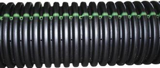
Recommendations for installation of external drainage systems made of galvanized steel
- We advise you to use drains from our production.
- All calculations and recommendations below are approximate.
- In each individual case, we recommend consulting with specialists.
At the first stage, after deciding to install a drainage system, it is necessary to calculate the number of drainage risers depending on the roof area of the building. Drainpipes with a diameter of 100 mm provide water drainage from a roof area of up to 70 square meters, and drainpipes with a diameter of 140 mm. from roof area to 90-100 square meters. It is recommended to maintain a distance between drainpipes of no more than 16 meters. Depending on the design of the building, drainage systems can be installed with or without gutters.
- If the project involves the installation of gutters.
- Determine the horizontality of the roof edges; for further consideration of the number of funnels and the slope of the gutter, see Fig. eleven)
- To determine the installation location of drainage funnels (or gutters with a pipe), see Fig. 1 (2) Clarification: the length of the gutter L with a slope in one direction should not exceed 8 meters, see Fig. 13)
- Place the attachment points for the outer brackets for the gutters, bend and secure them if necessary, see Fig. 1 (4.1) and Fig. 1 (4.2)
- Distance A min=80 mm, B max=160 mm. Pull a cord between the outer brackets for gutters, Fig. 1 (4.1) and 1 (4.2), through the center of the bottom of the bracket, Fig. 2
- Mark the mounting locations of the brackets according to the level of the cord, Fig. 1 (4), bend and secure them. Clarification: the recommended distance between the brackets for the external drainage gutter should not exceed 700 mm, see Fig. 1. Usually the distance is made from 500 mm. up to 700 mm. depending on the diameter of the drainage system, the larger the diameter, the shorter the distance. The bracket is bent in such a way that when fastened, the center of its bottom coincides with the tensioned cord, and the end fits tightly to the sheathing, see Fig. 2 and Fig. 3.
- We mount the gutter funnel (gutter with pipe), see fig. 12). The gutter funnel is secured with two brackets, see Fig. 1 (4.2) and 1 (4.3), the distance between which should be 200 mm.
- We install the required number of gutters, securing them in a special clamp on one side and securely clamping them with petals on the other, see Fig. 3 (5). Clarification: gutters are connected by sliding into each other along guides to a depth of 100 mm. A gutter connector is not required in this case.
Installation of drainpipes.
To begin installation, it is necessary to determine the attachment point of the upper clamp (bracket) for the drainpipe, Fig. 4 (1), taking into account the 60° elbow angle and the width of the cornice (a). Note: The attachment point of the top bracket should be at the level of the knee joint, fig. 4 (2), with pipe, figure 4 (3).
- Secure the upper clamp (bracket) for the pipe, Fig. 4 (4). Drill a hole d=11 mm and drive the pin of the clamp (bracket) for the drainpipe into the wall. Note: the recommended distance from the bracket to the wall should be 50 mm, fig. 6(b).
- Attach a plumb line to the upper clamp (bracket).
- Align the remaining brackets plumb. Note: distance between brackets. Fig.4 (c), should not exceed 1150 mm.
- If necessary (if the distance is more than 400 mm), determine the length of the intermediate part of the pipe, Fig. 4 (1) When calculating, take into account the distance (d), fig. 4 (4) and the elbow deflection angle is 60° Note: when determining the length of the intermediate part, it is necessary to add an allowance of 200 mm to connect the pipe with the elbows, Fig. 4 (1).
- Assemble a section of two elbows and an intermediate part of the pipe.
- Place it on the funnel and insert it into the top bracket.
- Install straight sections of the drainpipe, inserting them sequentially in the direction of water flow.
- Install the lower bend, fig. 4 (5). Note: the junction of the lower bend with the pipe must be secured with a bracket, fig. 4 (6).
We also suggest that you read other articles that will help you make the right choice:
Source
Plastic drainage trays NikA-Shop52
Plastic drainage trays.
Drainage or drainage gutters are the main element of storm drainage. Plastic drainage trays are an excellent alternative to concrete trays. The technical characteristics of plastic allow the use of plastic drainage trays on almost any facility up to load class E600 in any climatic zone.
Application of plastic trays The use of plastic trays for surface drainage in private construction is due to the ease and speed of installation.
Plastic gutters are also used in the arrangement of parks, embankments, and gas stations. For multi-level parking lots, there are special shallow plastic trays.
The availability of plastic storm channels makes it possible to use them in the construction of any objects, except those where load class F900 is planned.
— Plastic gutters can be connected to the sewer system. At the bottom of the tray there is a vertical drain flange for connecting a sewer pipe. — The design of the plastic tray provides for the possibility of corner connection of the trays.
— Drainage channels made of plastic have a laying strip to firmly hold the tray in the concrete base. — Drainage channels (gutters) are connected to each other using a special connecting flange and have a seam to seal the connection. If necessary, these seams can be filled with sealant.
Seams treated with sealant extend the life of the drainage system.
Performance characteristics of plastic drainage trays:
Plastic trays are lightweight, which simplifies transportation and installation of the drainage system; the zero moisture absorption coefficient of plastic trays makes them resistant to high and low temperatures
smooth surface does not retain dirt and debris, plastic trays are less prone to clogging
Types of plastic drainage channels
Plastic trays are divided into the following groups:
- according to the internal cross-section, plastic trays are distinguished DN90, DN100, DN150, DN200, DN300 - according to the load class, plastic channels can withstand loads from 1.5 tons (load class A15) to 60 tons (class E600) - according to the configuration, drainage gutters can be with and without reinforcing attachments. Trays with grids and trays without grids are also available
Installation and installation of plastic trays:
Storm plastic trays are installed by one person. They are easily joined and stacked; if necessary, the plastic tray can be cut with a regular hacksaw to the required length.
Operating a surface drainage system with plastic trays does not require much effort. Channels rarely become clogged, and cleaning is usually necessary in the spillway areas.
To clean an entire line of trays, you need to remove one grid at the beginning, middle and end of the line and rinse the line with a high-pressure stream of water.
Installation of drainpipes
Installation of drainpipes Scope of operations and controls
Same
Visual
| Stages of work | Controlled Operations | Control (method, volume) | Documentation |
| Preparatory work | Check: — availability of documents on the quality of workpieces; — checking the completeness, marking and quality of workpieces; — strength of installation of pins with grips, tag for fastening pins. | Certificate, passport, general work log | |
| Installation of drainpipes | Control: — the mounting height of the outlet elbow and the angle of inclination; — installation of pipe joints; — fastening of pipe links with clamps; — correct connection of the funnel to the tray and fastening to the overhang; - primer, color uniformity. | General work log | |
| Acceptance of completed work | Check: - the actual position of the installed drainpipes, the correct connection of the funnel with the tray; — appearance of elements. | Acceptance certificate for completed work | |
| Control and measuring tools: metal tape measure, ruler, template, reference. | |||
| Operational control is carried out by: master (foreman). Acceptance control is carried out by: quality service workers, foreman (foreman), representatives of the customer’s technical supervision. | |||
Technical requirements
SNiP 3.04.01-87 clause 2.46, table. 7
Not allowed:
bypassing protruding parts of the facade using knees; fastening drainpipes with wire.
Instructions for carrying out work
SNiP 3.04.01-87 clause 2.46,
Joints in pipes are made along the flow of water, pushing the links one into the other until the stiffening roller of the pipe.
Drainpipes made of non-galvanized steel after repairs or installations must be painted with oil paints or nitro paint over chemically resistant enamel paint DP.
Before painting, new links must be primed with drying oil, and old links must be cleaned of rust and oiled in places where the old paint has peeled off.
Permissible deviations:
- sections of pipes from the vertical by 1 m - 10 mm;
— drainpipes on the facade must be hung strictly vertically, set back from the wall by 120 m and attached to the wall every 1200 mm with pins driven into the wall to a depth of 0 mm with grips;
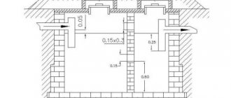
The entrance opening of the mark should be located no higher than 400 mm and no lower than 200 mm above the level of the sidewalk (blind area).
Source
Methods of strengthening
Strengthening the ditch with masonry
The design of the drainage ditch is a simple, non-durable structure. However, without any special expenses, the drain can be turned into a decoration of the estate’s landscape.
The unformed earthen walls of the drainage system are washed away by water flows and crumble, which leads to clogging and deterioration of the drainage properties of the channel. This problem is easily solved by strengthening the slopes. The choice of the most optimal method depends on the type of soil and the desired result.
- The channel gutter is lined with natural stone.
- Ornamental shrubs or wild grasses with a developed root system that reliably secure the slopes are planted along the edge of the canal.
- Strengthening drainage walls with a three-dimensional geogrid.
- Turfing the upper part of the slope: fastening the pieces of turf is done with special wooden knitting needles.
- The use of geomats consisting of three-layer plastic gratings.
- Application of gabions.
- On clay soils, good results are achieved by using geotextiles covered with a thick layer of sand or crushed stone.
- For a summer cottage, a budget option is acceptable: strengthening slopes with old sheets of slate or car tires.
In all cases, having strengthened the side walls, it is necessary to strengthen the bottom by creating a 5-10 centimeter layer of sand, crushed stone, gravel, rock or broken brick.
What are the SNiP requirements for drainage systems? At what distance from the entrance is the drain located?
Please write, the house has 5 floors, external drainage was installed a meter from the entrance. In the spring, water from the roofs first melts onto the sidewalk and freezes at night. Does this all comply with SNiP? I can't find anything about this in the documents. On which side of the house is the drain installed, how many meters from the entrance is the minimum distance? Video attached. Thank you.
You have installed an external drainage system, which can be installed on houses of no more than 5 floors, inclusive.
This system is regulated by the following documents:
SNiP II-26-76 -> SP 17.13330.2011 -> SP 17.13330.2017 see the latest edition, called:
But this document not only does not indicate the distance, but also the rules for installing the lower (outlet) hole of the drain pipe.
You will not find these standards in other SNIPs.
If you think logically, the above document regulates how water should drain from the roof, but where it drains is the tides or sewerage.
SNiP 2.04.03-85 Sewerage. External networks and structures
There is also no information about water intake.
The only thing I could find was this document:
SNiP 2.04.01-85* BUILDING STANDARDS AND RULES INTERNAL WATER PIPING AND SEWERAGE OF BUILDINGS
Clause 20 of this document stipulates internal drainage with a note in subclause 20.3 about when the water is discharged to the outside:
20.3. In the absence of rainwater drainage, the discharge of rainwater from internal drains should be received openly into trays near the building (open discharge); in this case, measures should be taken to prevent erosion of the ground surface near the building.
Note. When installing an open outlet on a riser inside the building, a hydraulic seal should be provided to drain melt water into the domestic sewer system in the winter.
So, the result of this question is this - the distance of the drainage from the entrance is not specified in SNIP, but based on paragraph 20.3 of SNIP 2.04.01-85, it turns out that water from the drainage must fall into the tray, and then the rules of external sewerage come into force, SNIP 2.04 .03-85 and 2.04.02-85.
In simple words, water from the drain should flow into the tray and then into the storm drain.
Source
Storm drainage of roads, bridges, junctions
Surface storm water runoff from roads, junctions and bridges must be drained and cleaned. For this purpose, utility systems are used that collect wastewater generated on the surfaces of transport communications, separate the impurities contained in them, and then discharge the wastewater. develops, produces at its own production facilities and installs modern storm sewers for highways, interchanges and bridges, which are highly efficient, easy to operate and maintain.
Advantages of “storm drains” of transport communications from
Storm sewers for roads, bridges and interchanges, designed, manufactured and installed, contain many fiberglass elements. They are characterized by high mechanical strength, resistance to chemical environments, ease of installation and maintenance. The cost of such systems is low, and their service life is
several decades.
Types of storm drainage for transport communications
Storm drainage under the road is a closed type system. It includes a network of underground communications, through which wastewater is first directed to treatment facilities, and then discharged either to sewers or to various environmental objects. Mixed-type storm drains are combinations of open and closed storm drains.
New exit to the Moscow Ring Road from the federal highway M-1 Belarus Moscow-Minsk
Main elements of stormwater drainage on roads, junctions and bridges
Almost every modern storm drainage system on roads, bridges and junctions consists of such basic elements as storm water inlets, gutters, pipeline communications and treatment facilities. All these components together make it possible to collect, purify rainwater, irrigation and melt water, and carry out their timely drainage.
Reconstruction of Borovskoye Highway
Treatment facilities for highways, bridges, interchanges
Treatment facilities for roads, interchanges and bridges are necessary in order to bring the discharged wastewater to conditions that allow it to be discharged. they are implemented based on the principle of gradation. This means that first the wastewater goes through the stage of separation of solid impurities (sand separators), then it enters the oil and petrol separators. The presence of these devices is due to the fact that transport inevitably pollutes storm drains
highways, bridges and interchanges with various petroleum products (fuel, oils). Oil and petrol separators are equipped with coalescent modules, thanks to which organic compounds suspended in wastewater are deposited on their surfaces, become larger and float, forming a film. The post-treatment of wastewater is carried out in a sorption unit, after which the water is discharged onto the terrain, into reservoirs or sewers.
Design and construction of access roads to a sports and entertainment center and a yacht club
Installation of a drainage system: calculation and installation process
The final stage of the roof installation is the installation of the drainage system. Among the various systems, you need to choose the one that suits your requirements - metal with galvanic coating or plastic. Gutter manufacturers offer a full range of components. For information on how to perform the installation itself, read the article.
Drainage system in operation
Calculation of components
Based on the size and shape of the roof, you can independently calculate how many pipes, gutters, brackets and other parts of the drainage system you will need.
Based on the size of the roof, we select the diameter of the gutters:
- If the roof area is less than 50 m2, gutters 100 mm wide and pipes 75 mm in diameter are used.
- Up to 100 m2, 125 mm gutters and 87 mm pipes are used.
- More than 100 m2 - gutters 150 mm and pipes 100 mm (the use of gutters 190 mm and pipes 120 mm is allowed).
In the case of a complex roof structure, gutters and pipes are determined by the largest projection size of the roof part.
Calculation of the number of pipes
Scheme for determining roof area
The roof area, consisting of parts, is 160 m2. Considering that one drain pipe is enough to service 100 m2 of roofing in projection, for the roof in the example you will need 2 drain pipes located at the corners of the house. The number of funnels corresponds to the number of pipes, i.e. - 2 pieces.
The number of vertical pipes is determined depending on the distance from the cornice to the blind area. Subtract 30 cm from this distance - the height of the drain elbow above ground level.
For example, the height to the cornice is 7.5 m. Then 7.5 m -0.3 m = 7.2 m.
We will need 3 pipes of 3 m each on each side, which means 6 pipes on both sides.
The number of clamps will be 5 for each side (between the elbow and the pipe, between the pipe and the ebb, and between the pipes) and, accordingly, 10 pieces for the entire roof.
Subtract 30 cm from the distance from the cornice to the blind area
Calculation of the number of gutters
The most commonly used gutter size is 3 meters. The length of cornice A and cornice B is 10.3 m. This means we need:
- There are 4 gutters on cornice A (3m + 3m + 3m + 1.3m). This will leave us with another 1.7 m of unused gutter.
- On cornice B there are 3 gutters and the remainder (1.7 m) from cornice A.
- For eaves C and D we use 2 gutters each, that is 4 pieces on both sides.
- In total, 11 gutters of 3 m each for the entire roof.
The number of gutter corners corresponds to the number of roof corners, in our example there are 4.
Calculation of the number of brackets and gutter locks
The brackets are installed at the rate of 1 piece per approximately 50-60 cm. We take 50 cm and carry out the calculations.
| Number of gutters, pcs. | Gutter length, m | Number of brackets on the gutter, pcs | Total number of brackets, pcs. |
| 8 | 3 | 6 | 42 |
| 2 | 2,5 | 5 | 10 |
| 2 | 1,3 | 3 | 6 |
Having summed up the numbers in the last column, we find out that in order to attach the gutters, we will need 58 brackets.
Determining the number of locks between gutters
The number of locks between the gutters is equal to the number of joints. In our case, this is 16 pcs.
Calculation of the number of knees
The number of ebbs (marks) is equal to the number of funnels. In this case, you need 2 times more knees for each funnel. Then for 2 funnels you need:
If the facade is not level, but has protrusions, you need to purchase elbows to go around it. The figure below will help you determine their number.
Determining the number of bends to bypass the protrusion on the facade
List of required items
In total for this drainage system you will need:
- Gutter (3 m) – 8 pcs.
- Gutter (2.5 m) – 2 pcs.
- Gutter (1.3 m) – 2 pcs.
- Gutter lock – 16 pcs.
- Gutter angle – 4 pcs.
- Bracket – 58 pcs.
- Knee – 4 pcs.
- Drain elbow (mark) – 2 pcs.
- Pipe (3m) – 6 pcs.
- Funnel – 2 pcs.
- Clamp (with pin) – 10 pcs.
If you correctly calculate the drainage capacity, the system will cope with its functions of water drainage, protecting blind areas, walls, and roofing elements.
Plastic trays, channels, gutters
Plastic channels are a modern and promising version of the drainage system. Today, plastic is a popular material that is widely used in construction. Its frost-resistant and heavy-duty compositions have proven themselves in the production of elements for drainage systems at sites with low and medium loads on the road surface.
Plastic drainage trays are increasingly being used to equip urban infrastructure facilities. Parking lots, small gas stations, roadsides, parking lots, sidewalks, areas of residential country houses - just a small list of those objects where these plastic systems are successfully used.
The growing demand for plastic drainage trays is due to the following advantages:
- Long service life. Modern polymer compositions make it possible to obtain products with high strength characteristics, resistant to aggressive environments, temperature changes, and ultraviolet radiation.
- Increased throughput. Plastic drainage gutters have a perfectly smooth inner surface. Thanks to this, dirt and debris do not settle on the walls of the trays and the system remains clean for a long time, which significantly saves the cost of its maintenance.
- Light weight of elements. Plastic is a lightweight and durable material. Plastic trays have fairly thin walls. Overall the design is very light. This reduces the cost and simplifies the transportation of the system and its installation.
- Possibility of connection with sewer pipes of different diameters. The tray has several outlets of standard diameters for connecting to the sewer network.
- Simplicity and ease of installation. Installation of plastic trays does not require much labor. Plastic is easy to process, so channels can be installed in any conditions by shortening or aligning standard elements in place. The design of plastic channels provides for their connection at an angle of 90º.
Properly designed and installed to meet the pavement load requirements of a particular area, a plastic drainage system will provide many years of service.
Plastic channels are more expensive than concrete ones. However, their advantages during installation, maintenance and long service life allow you to save considerable money. If the load on the coating at your facility is not large, the choice in favor of plastic trays is obvious.
It’s easy to buy plastic trays at a good price - call and order!
Installation of brackets and gutters
Fastening the drainage system begins with marking the installation locations of the brackets using a marking thread.
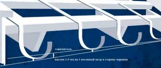
The center of the gutter should be located below the bottom edge of the roof. The gap between the line (shown in dotted lines in the diagram) of the continuation of the roof and the top of the gutter holder must be at least 25 mm.
Properly secured bracket
The funnel is installed above the storm drain. The funnel must be secured to two brackets or at two points. The location of the funnel can be in the center or at the edge (set in the project). A hole is cut in the gutter using a hacksaw to the size of the funnel.
Funnel embedded in a gutter
The brackets are fixed to the gutter line (the slope of the gutter line towards the funnel is from 2 to 5%). The installation pitch of the brackets is from 0.5 to 0.75 m (for selection, use the manufacturer’s “Installation Instructions for the Drainage System”). The extreme bracket is attached at a distance of 25-30 cm from the plug at the end of the gutter. The distance from the corner element to the bracket is no more than 15 cm.
The gutters are inserted into the brackets, starting from the rear, and plugs are installed at the ends. The joints of the gutters are fixed with special locks or connecting elements. The ends of the gutters should be located 50-100 mm behind the side edge of the roof. If the roof span is more than 8 m, an expansion element must be installed between the gutters.
Types of fastening and material of brackets
- The brackets are installed on the rafter leg. Metal brackets are used.
- When using a frontal (gable) board, plastic brackets are used.
- The brackets are attached to the deck using metal extensions. Use plastic or metal brackets.
Different types of fastening
Possible errors and consequences
- An increased pitch between the brackets leads to sagging of the gutters.
- The mismatch between the edge of the roof and the middle of the gutter leads to overflow.
- Increasing the gap between the gutter line and the edge of the roof - splashing and overflow.
When cutting gutters and pipes, the use of angle grinders is not allowed, as the coating is damaged and burrs remain. Cutting is done with a hacksaw for metal. It is recommended to clean the cut ends with a file.
What kind of water interferes with the life of a developer and a country homeowner?
A whole book could be written about the types of surface and ground water, as well as drainage and storm sewer systems. Therefore, we will leave beyond the scope of this article a detailed listing of the types and causes of groundwater occurrence, and will concentrate on practice. But without minimal theoretical knowledge, starting to independently arrange drainage and storm sewer systems is throwing money away.
The fact is that even an incorrectly designed drainage system functions for the first few years . Then, due to clogging (siltation) of the drainage pipe, wrapped in geotextile, which was placed in clayey, loamy, etc. soil, drainage stops working. But money has already been spent on drainage construction and, most importantly, drainage construction involves a large amount of excavation work involving equipment.
Therefore, simply digging up and relaying a drainage pipe 3-5 years after it was laid is difficult and costly. The site has already been inhabited, landscaping has been done, a blind area has been arranged, a gazebo, a bathhouse, etc. have been installed.
You will have to rack your brains on how to redo the drainage so as not to ruin the entire area.
Hence, the construction of drainage should always be based on data from a geological study of the soil (which will help to find a waterproof layer in the form of clay at a depth of 1.5-2 m), hydrogeological surveys and clear knowledge of what kind of water leads to flooding of a house or waterlogging of an area.
Surface waters are seasonal in nature, associated with the period of snowmelt and abundance of rain. Groundwater is divided into three main groups:
- Capillary water.
- Ground water.
- Verkhovodka.
Moreover, if surface water is not drained in time, it turns into underground water when infiltrated (absorbed) into the ground.
The volume of surface water usually exceeds the volume of groundwater.
Conclusion: surface runoff should be drained away by storm (rain) sewerage, and not try to create surface drainage!
Storm drainage is a system consisting of trays, pipes or ditches dug in the ground, discharging water from drains outside the site + competent organization of the relief on the personal territory. This will allow you to avoid stagnant zones on the site (lenses, pools), where water will accumulate, which simply has nowhere to go, and further waterlogging.
The main mistakes that are made when installing drainage yourself:
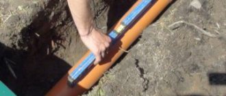
- Failure to maintain the correct slope of laid drainage pipes. If we take an average, then the slope is maintained in the range from 0.005 to 0.007, i.e. 5-7 mm per 1 running meter of drainage pipe.
- Using a drainage pipe in a geotextile wrap on “wrong” soil. To avoid siltation, pipes in geotextiles are used on soils consisting of clean medium- and coarse-grained sands.
- Using cheaper crushed limestone instead of granite, which is washed away by water over time.
- Saving on high-quality geotextiles, which must have certain hydraulic properties that affect the quality of drainage. This is an effective pore size of 175 microns, i.e. 0.175 mm, as well as transverse Kf, which should be at least 300 m/day (with a single pressure gradient).